
Subscribe to Our Youtube Channel
Related Manuals for ARRI UMC-4


Summary of Contents for ARRI UMC-4
- Page 1 UMC-4 UMC-4 Universal Motor Controller Universal Motor Controller U S E R M A N U A L U S E R M A N U A L 18th October 2017 18th October 2017...
- Page 2 Richter Cine Technik GmbH & Co. Betriebs KG. Specifications are subject to change without notice. Errors, omissions, and modifications excepted. ARRI, ALEXA, AMIRA, Master Grip, LDS and LENS DATA SYSTEM are trademarks or registered trademarks of Arnold & Richter Cine Technik GmbH & Co. Betriebs KG. All other brands or products are trademarks or registered trademarks of their respective holders and should be treated as such.
- Page 3 Neither ARRI nor its subsidiaries assume any liability for infringement of patents, copyrights or other intellectual property rights of third parties by or arising from the use of ARRI products or any other liability arising from the use of such products. No...
- Page 4 or its subsidiaries be liable for or have a remedy for recovery of any special, direct, indirect, incidental, or consequential damages, including, but not limited to lost profits, lost savings, lost revenues or economic loss of any kind or for any claim by a third party, downtime, good-will, damage to or replacement of equipment or property, any cost or recovery of any material or goods associated with the assembly or use of our products, or...
-
Page 5: Table Of Contents
Table of Contents Table of Contents For your safety..............7 Audience and intended use..........9 Scope of delivery and warranty........10 Introduction..............11 Quick start guide.............13 Layout UMC-4..............15 Soft Buttons............18 Optional Connector Modules........19 Home screen..............20 Radio............... 20 Lens.................21 Info................21 Focus / Iris / Zoom.......... - Page 6 Table of Contents LBUS devices..............37 Remote Access............... 38 11.1 Web Interface............38 11.2 VNC.................39 Metadata................40 Appendix................42 13.1 Antenna connector..........42 13.2 Part Numbers............42 13.3 Compatibility............44 13.4 Pinouts..............46 13.5 Dimensions and Weight.......... 49 13.6 Electrical Data............49 13.7 Radio system............50 13.8 Troubleshooting............51 13.9 Service contacts............52 13.10 International declarations........
-
Page 7: For Your Safety
For your safety For your safety Before use, please ensure that all users read, understand, and follow the instructions comprehensively in this document. Risk levels and alert symbols Safety warnings, safety alert symbols, and signal words in these instructions indicate different risk levels: DANGER! DANGER indicates an imminent hazardous situation, which, if not avoided, will result in death or serious injury. - Page 8 Use only the tools, materials and procedures recommended in this document. Unplug all cables during transport. Do not store the UMC-4 in places where it/they may be subject to temperature extremes, direct sunlight, high humidity, severe vibration, or strong magnetic fields.
-
Page 9: Audience And Intended Use
ARRI guidelines. Use the product only for the purpose described in this document. Always follow the valid instructions and system requirements for all equipment involved. The UMC-4 is solely and exclusively for use on professional camera setups. -
Page 10: Scope Of Delivery And Warranty
Universal Motor Controller UMC-4, including antenna L-Bracket SD card Instruction manual Original packaging Warranty For scope of warranty, please ask your local ARRI Service Partner. ARRI is not liable for consequences from inadequate shipment, improper use, or third-party products. -
Page 11: Introduction
The Universal Motor Controller UMC-4 is an advanced 3-axis motor controller. Up to three different hand units can connect to the UMC-4 at the same time, controlling focus, iris and zoom on any camera. The intuitive user interface helps to quickly setup the system and makes it easy to use. - Page 12 How to use this manual Connectors are all written in capital letters, for example, LCS. Buttons are all written in capital letters, for example, MENU soft button. Menus and screens are written in italic letters, for example home screen. The appendix at the back of the manual contains useful reference material including radio frequencies, spare parts and additional accessories, connector pin-out diagrams and dimensional drawings.
-
Page 13: Quick Start Guide
Quick start guide This quick start guide walks you through the required steps, to set up the UMC-4 with three motors and a wireless hand unit. Mounting on camera Mount the UMC-4 on the camera, by using the L-Bracket, with the antenna pointing upwards and the motor connectors pointing towards the lens. - Page 14 Quick start guide Connecting to Hand Unit Set the radio channel on the UMC-4 in the Radio sub-page of the Home screen. Make sure that the radio power is switched on and that the selected radio channel is not already in use. Set the hand unit to the same radio channel.
-
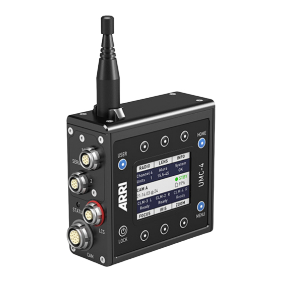
Page 15: Layout Umc-4
Layout UMC-4 Layout UMC-4... - Page 16 Rugged outdoor antenna SERIAL Interface Two serial interface connectors to attach Module peripheral equipment like Ultrasonic Dis- tance Measure UDM-1. Note: Further protocols will be added with subsequent software updates. Optional modules: (1) UMC-4 connector module to Canon fo- cus/zoom demands CAN-1...
- Page 17 Layout UMC-4 (2) UMC-4 connector module to Fujinon fo- cus/zoom demands FUJ-1 Status LED Indicates controller status: Blue radio connection is estab- lished, motors are cali- brated, no warnings Green wired connection is es- tablished, motors are cali- brated, no warnings...
-
Page 18: Soft Buttons
BACK (or depending on the context, the CANCEL) soft button. POWER/LOCK Button Press and release to switch the UMC-4 on; to switch off the UMC-4, the button must be pressed for three seconds, and a countdown is displayed. If the button is released before the countdown has elapsed, the UMC-4 does not shut down. -
Page 19: Optional Connector Modules
The installation of the connector modules requires basic skills and knowledge of electronics. Please follow the installation instructions delivered with the modules or contact ARRI Service. K2.0002043 Module to Fujifilm focus/zoom demands FUJ-1 K2.0002042 Module to Canon focus/zoom demands CAN-1... -
Page 20: Home Screen
Home screen Home screen The Home screen is the default screen. It shows the most important parameters and gives quick access to changing them through the six soft buttons: Radio The RADIO soft button area displays the currently selected radio channel and the number of connected hand units. -
Page 21: Lens
The live info screen displays the UMC- 4’s current system state and current error messages, and provides the following sub-screens: SYSTEM: Shows the UMC-4 firmware version, the • device’s serial number and the voltage level of the power... -
Page 22: Info Area
(if set), timecode (if active), the camera status (STBY, REC, PREREC, ERASE, PLAY) and SD card status. Playback control Full playback control from WCU-4 is possible with the UMC-4 connected to AMIRA or ALEXA Mini. NOTICE The Playback and Erasing indication is only supported on... -
Page 23: Menu
Menu Menu The Menu contains parameters for the basic UMC-4 setup. It has a tree structure and the current path in the menu is displayed in the top section of every screen. Motors The Motors menu lets you set up the focus, iris and zoom motor, calibrate motors and select the calibration speed. - Page 24 The correct teeth count setting is crucial for lens metadata generation as well as correct displayed lens data on hand units. Currently, only ARRI gears with 40, 50 or 60 teeth are supported. Any manual gear selections remains persistant until changed again.
-
Page 25: Radio
Menu Attach the LDE-1 to the lens and connect it to its respective motor connector on the UMC-4 (e.g. if it encodes the focus scale, connect it to the FOCUS motor socket). Press CALIBR. or CAL. ALL to activate calibration mode. -
Page 26: Lens
Custom lens tables can be added to the Lens Data Archive’s Custom folder via SD card. To add a new lens table to the UMC-4, copy the lens table on the SD card and insert the SD card into the UMC-4. -
Page 27: Metadata
Wireless Compact Unit WCU-4 (SUP 2.0 onwards) Copying Lens Tables to SD Card Lens tables located in the UMC-4 Custom folder of the Lens Data Archive can be copied to the SD card. Go to Menu>Lens>Copy from SD Card to copy all lens tables from the Custom folder to the SD card’s /ARRI/ALEXA/LDA... - Page 28 Record Mode Set Record Mode to Auto if you want metadata to be recorded to SD card each time the UMC-4 gets a tally (recording) feedback from the camera it is connected to. Set to Manual if you want to start metadata recording to SD card manually.
- Page 29 Level Shows the tilt and roll of the UMC-4 in degrees, as measured by the internal inclinometer. This sensor can be reset if it appears to have an offset. Press the RESET soft button to reset the sensor.
-
Page 30: Focus/Zoom Demands Menu
To calibrate the limits for a demand, connect the demand to the UMC-4 and set the zoom speed control knob to the highest speed setting (‘Fast’ or ‘Max’). Select Menu>Focus/Zoom Demands>Set Limits. Press the FOCUS or ZOOM button and start turning the demand’s control... -
Page 31: System
Color Theme offers various color themes for the UMC-4 display. Display Backlight lets you set the backlight intensity for the LCD screen. Button Backlight lets you set the backlight intensity for all UMC-4 control buttons. Select Enter Sleep After to set the sleep mode timing. -
Page 32: Settings
“UMC4-####.local”, where “####” stands for the UMC-4 serial number. For simple setups consisting of a PC and one or more UMC-4 units, connect the PC to the UMC-4 using a standard Ethernet cable. Make sure that your PC supports Bonjour protocol (e.g. -
Page 33: Firmware Update
Select Factory Defaults to load the factory defaults into the UMC-4. NOTICE The current settings in the UMC-4 will be lost after loading a settings file! The current settings in the UMC-4 will be lost after loading the factory defaults! 8.6.5... -
Page 34: Lbus Update
Menu 8.6.6 LBUS update The UMC-4 is capable of updating LBUS devices. Insert a FAT32 formatted SD card into the UMC-4.To connect the devices a LCS to LBUS cable is required. Also an additional power supply cable is mandatory. See "Part Numbers", page 42 Go to Menu>System>LBUS Device... -
Page 35: Save Log To Sd Card
ARRI support staff. The log file will be saved immediately and can be found in the /ARRI/UMC4/logs directory. 8.6.8 Format SD Card Select Format SD Card to format the SD card and add the ARRI specific directory structure: /ARRI/UMC4 /Firmware... -
Page 36: User
Pressing the USER button a second time will switch to a configuration screen, where each button can be assigned to one of the pre-defined functions. On delivery the UMC-4 comes with factory-programmed functions on each user button. To change them, enter the configuration screen by pressing the USER button twice. -
Page 37: Lbus Devices
See "LBUS cables", page 43 LBUS motors will be overruled by passive motors connected to the UMC-4. Make sure, to disconnect passive motors on those axis on which you want to use LBUS motos. LBUS hand-units will be overruled by wireless connected hand... -
Page 38: Remote Access
The UMC-4 includes an embedded web server that can be accessed through a web browser using Apple’s Bonjour® protocol. To access the UMC-4 web interface, connect the UMC-4 to a computer with a standard Ethernet cable. Open the web browser on the computer. Enter address umc4-####.local, with #### being the UMC-4 serial number. -
Page 39: Vnc
VNC Viewer. There are many VNC clients for virtually all operating systems that can be used with the UMC-4. As an example, the VNC Viewer can be downloaded from https://www.realvnc.com/ download/viewer/. Please follow the installation instructions from the RealVNC website. -
Page 40: Metadata
Metadata Metadata The UMC-4 records a metadata file when the camera is recording a clip as long as the UMC-4 receives a tally signal from the camera. CAUTION! Make sure to insert a write-enabled SD card with enough free space into the UMC-4. Set the UMC-4 to automatic recording mode (Menu>Metadata>Recording Mode>Auto) to trigger... - Page 41 Minimum encoder limit of zoom motor EncoderLimFocalMotorMax Maximum encoder limit of 21122 zoom motor EncoderLimIrisMotorMin Minimum encoder limit of iris motor EncoderLimIrisMotorMax Maximum encoder limit of iris 4585 motor UMC-4 Tilt Tilt angle of UMC-4 (degree) UMC-4 Roll Roll angle of UMC-4 (degree)
-
Page 42: Appendix
K2.0001967 L-Bracket (supplied with UMC-4) K2.0001758 V-Plate K2.0002007 Outdoor Antenna (straight) for UMC-4 Motor Controller (supplied with UMC-4) K2.0001637 Cable Fi m3p to Fi f3p Provides power and RUN/STOP function. Can be used to power a UMC-4 from a camera. - Page 43 UMC-4 connector module to Fujifilm focus/zoom demands FUJ-1 K2.0002042 UMC-4 connector module to Canon focus/zoom demands CAN-1 K2.0002046 UMC-4 connector module with two serial connectors (supplied with UMC-4) LBUS cables K2.0006749 Cable LBUS 0,2 m/8" LCB-3 K2.0006750 Cable LBUS 0,3 m/1 ft LCB-4 K2.0006751...
-
Page 44: Compatibility
Risk of fire! Short-circuits and back currents to power supplies/batteries may entail lethal damage! Always use original ARRI/cmotion LBUS cables to external power sources (D-Tap, XLR)! ARRI/cmotion LBUS cables to external power sources provide a protection circuit to prevent back currents to power supplies/batteries. - Page 45 ARRI ALEXA and AMIRA cameras • 3rd party cameras • cmotion cfinder III • NOTICE Use only one lens motor per lens axis. Up to three hand units can be connected to one UMC-4 in parallel to form a radio network.
-
Page 46: Pinouts
D-CAM Tally, digital input, TALLY active low DAC-CAM REC analog output, active high (default value @REC: 3.3V) ARRI R/S RUN-SW2 Opto switch 2 connects to pin 5 @REC (max. 100 mA/50V) RxD/Rx+ RS232/RS485 – RS422 together with pins 4, 6, 15 TxD/Tx- RS232/RS485 –... - Page 47 Appendix CAN-H CAN bus Serial connector Ground V-IN Battery supply in-/output RS232 RS422 RXTX-N RS485 RS232 RS422 RXTX-P RS485 RS422 RS422 CABLE-ID Analog input LCS connector Ground n.c. CAN-L CAN bus CAN-H CAN bus +V-BAT Battery supply output CLM connector Ground MTYPE-A Motor type sense...
- Page 48 Encoder-B Encoder input B 8/9/10 n.c. Motor + Motor drive output Motor - Motor drive output RS IN Ground +V-BAT 9.5 V to 34 V DC IN ARRI R/S Ground LTC-IN Timecode input n.c. n.c. n.c. n.c. LTC-OUT Timecode output...
-
Page 49: Dimensions And Weight
Appendix 13.5 Dimensions and Weight Weight (including antenna): 428 g / 15.1 oz 13.6 Electrical Data Supply Voltage: 9.5V to 34V DC (full motor speed) Current Consumption: 135 mA@12V (radio on/ready) 70 mA@24V (radio on/ready) Operating Temperature: -20 to +50 °C (-4 to +122 °F) -
Page 50: Radio System
Appendix 13.7 Radio system The UMC-4 contains a radio unit that enables wireless lens control with a white coded radio module. A white ring at the base of the antenna socket identifies it. There are 8 channels to choose from:... -
Page 51: Troubleshooting
The UMC-4 does not The internal lithium bat- does not boot up after pressing the tery might be empty. power up POWER button. Press the power button for 3-5 seconds to power up the UMC-4. Have the internal battery replaced by ARRI Service. -
Page 52: Service Contacts
Appendix 13.9 Service contacts Munich, Germany Vienna, Austria Arnold & Richter Cine Tech- ARRI Cine + Video Geräte Ges.m.b.H. +49 89 3809 2121 +43 1 8920107 30 service@arri.de service@arri.at Business hours: Business hours: Mo. - Fr. 9:00 - 17:00 (CET) Mo. -
Page 53: International Declarations
Appendix 13.10 International declarations EC Declaration of Conformity The product UMC-4 conforms to the specifications of the following European directives: Directive 2014/30/EU of the European Parliament and the Council of 26 February 2014 on the harmonization of the laws of the Member States relating to electromagnetic... - Page 54 It may not be legal to operate Universal Motor Controller UMC-4 in a country/region other than the country/region selected in the UMC-4 region menu. Switch radio off and use the device in hardwired mode if you are not sure of the correct...
Need help?
Do you have a question about the UMC-4 and is the answer not in the manual?
Questions and answers