Table of Contents
Advertisement
Quick Links
Advertisement
Table of Contents

Subscribe to Our Youtube Channel
Related Manuals for ARRI UMC-4


Summary of Contents for ARRI UMC-4
- Page 1 UMC-4 Universal Motor Controller U S E R M A N U A L Date: 9 February 2015...
- Page 2 Page 2 of 54 Universal Motor Controller UMC-4 – User Manual – V 02/2015...
- Page 3 This instruction manual applies to the following product: Universal Motor Controller UMC-4 with Software Update Package (SUP) 1.1 Document Information Version Document No. Date K5.0003467 28.08.2014 K5.0003467 09.02.2015 Universal Motor Controller UMC-4 – User Manual – V 02/2015 Page 3 of 54...
-
Page 4: Table Of Contents
Soft Buttons ..................21 Menu Navigation ................22 POWER/LOCK Button ..............22 HOME Button ................... 22 USER Button ..................22 MENU Button ................... 22 Page 4 of 54 Universal Motor Controller UMC-4 – User Manual – V 02/2015... - Page 5 Electrical Data .................. 50 Radio System ................... 50 Troubleshooting ................51 ARRI Service Contacts ..............51 International Declarations and Certifications ........52 Universal Motor Controller UMC-4 – User Manual – V 02/2015 Page 5 of 54...
-
Page 6: Disclaimer
The information is subject to change without notice. For product specification changes since this manual was published, refer to the latest publications of ARRI data sheets or data books, etc., for the most up-to-date specifications. Not all products and/or types are available in every country. - Page 7 In no event shall ARRI or its subsidiaries be liable for or have a remedy for recovery of any special, direct, indirect, incidental, or consequential damages, including, but not limited to lost profits, lost savings, lost revenues or economic loss of any kind or for any claim by third party,...
- Page 8 FreeRTOS V7.5.3 - Copyright (C) 2013 Real Time Engineers Ltd. All rights reserved. http://www.FreeRTOS.org VNC is a registered trademark of RealVNC Ltd. in the U.S. and in other countries. Page 8 of 54 Universal Motor Controller UMC-4 – User Manual – V 02/2015...
-
Page 9: For Your Safety
For Your Safety Always keep this document on hand. It should be read, understood and observed by all persons using the Universal Motor Controller UMC-4. All other products must be handled as prescribed by their manufacturers. Risk Levels and Alert Symbols... -
Page 10: Vital Precautions
Use only the tools, materials and procedures recommended in this document. Unplug all cables during transport. Do not store the UMC-4 in places where it may be subject to temperature extremes, direct sunlight, high humidity, severe vibration, or strong magnetic fields. -
Page 11: Introduction
Introduction The Universal Motor Controller UMC-4 is an advanced 3-axis motor controller. Up to three different hand units can connect to the UMC-4 at the same time, controlling focus, iris and zoom on any camera. The intuitive user interface helps to quickly setup the system and makes it easy to use. -
Page 12: How To Use This Manual
Instruction manual • Original packaging • For scope of warranty, please ask your local ARRI representative. ARRI is not liable for consequences from inadequate shipment, improper use, or third-party products. System Requirements To tap the full potential of the device, have all connected units updated to a firmware equal or higher to those listed below. -
Page 13: Quick Start Guide
Time and date are used in the naming of metadata files recorded to SD card, as well as in the log file. The UMC-4 will keep time and date even if it is disconnected from a power source, as it includes a built-in lithium battery that normally lasts for more than five years. - Page 14 Connect the motor cables to their respective FOCUS, IRIS and ZOOM connectors on the UMC-4. Go to the Focus, Iris or Zoom sub-page of the Home screen and press CAL. ALL to calibrate all motors. Page 14 of 54 Universal Motor Controller UMC-4 – User Manual – V 02/2015...
-
Page 15: Connecting To Hand Unit
Torque refers to the motor torque; a higher value means higher torque. Connecting to Hand Unit Set the radio channel on the UMC-4 in the Radio sub-page of the Home screen. Make sure that the radio power is switched on and that the selected radio channel is not already in use by another motor controller. - Page 16 Note: After connecting a lens motor to the UMC-4 and the lens, it must be calibrated. The lens motor must be recalibrated under the following conditions: When the lens motor is detached from the lens • After changing lenses •...
-
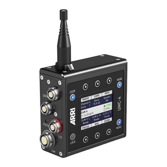
Page 17: Interfaces
Interfaces The UMC-4 includes multiple interfaces for maximum flexibility on set. Antenna SERIAL Interface Module Status LED Connector Connector FOCUS Motor Connector RS IN Connector IRIS Motor Connector Connector ZOOM Motor Connector Universal Motor Controller UMC-4 – User Manual – V 02/2015... - Page 18 Note: Further protocols will be added with subsequent software updates. Optional modules: UMC-4 connector module to Canon focus/zoom demands CAN-1 UMC-4 connector module to Fujinon focus/zoom demands FUJ-1 Page 18 of 54 Universal Motor Controller UMC-4 – User Manual – V 02/2015...
- Page 19 SD Card Slot Mounts an SD card 3/8” UNC Mounting Mounting point for accessories like L-Bracket or V- Point Plate M4 Mounting Mounting point for accessories Points Universal Motor Controller UMC-4 – User Manual – V 02/2015 Page 19 of 54...
-
Page 20: Optional Connector Modules
Two optional connector modules interface directly with broadcast-style focus and zoom demands from Fujifilm and Canon. They replace the standard SERIAL connector module that is delivered with the UMC-4. The installation of the connector modules requires basic skills and knowledge of electronics. Please follow the installation instructions delivered with the modules or contact ARRI Service. -
Page 21: Control Panel
Control Panel The UMC-4 features a comfortable and comprehensive user interface with backlit buttons enabling the user to quickly configure the system. The 2.4” transflective LCD display shows vital status information and is easily readable in any ambient light conditions. -
Page 22: Menu Navigation
(or depending on the context, the CANCEL) soft button. POWER/LOCK Button Press and release to switch the UMC-4 on; to switch off the UMC-4, the button must be pressed for three seconds, and a countdown is displayed. If the button is released before the countdown has elapsed, the UMC-4 does not shut down. -
Page 23: Home
The live info screen displays the UMC- 4’s current system state and current error messages, and provides the following sub-screens: Universal Motor Controller UMC-4 – User Manual – V 02/2015 Page 23 of 54... -
Page 24: Home>Focus
The info area in the center of the Home screen shows camera index (if set), timecode (if active), the camera recording status and SD card status. Page 24 of 54 Universal Motor Controller UMC-4 – User Manual – V 02/2015... -
Page 25: Menu
Note: Do not remove the SD card during recording! MENU The Menu contains parameters for the basic UMC-4 setup. It has a tree structure and the current path in the menu is displayed in the top section of every screen. -
Page 26: Motors Menu
Side: Select the side on which the motor or lens data encoder is mounted to the lens. Torque: Set the torque level for CLM-3 and CLM-4 motors. Page 26 of 54 Universal Motor Controller UMC-4 – User Manual – V 02/2015... - Page 27 To manually calibrate a Lens Data Encoder LDE-1, proceed as follows: Attach the LDE-1 to the lens and connect it to its respective motor connector on the UMC-4 (e.g. if it encodes the focus scale, connect it to the FOCUS motor socket).
-
Page 28: Radio Menu
Fig. 4: Focus Motor Menu Radio Menu The Radio menu lets you switch the radio on and off and select the radio channel. Select the same channel both on the hand unit and the UMC-4. Fig. 5: Radio Menu Lens Menu... - Page 29 Custom lens tables can be added to the Lens Data Archive’s Custom folder via SD card. To add a new lens table to the UMC-4, place the lens table on the SD card and insert the SD card into the UMC-4.
-
Page 30: Metadata Menu
Record Mode Set Record Mode to Auto if you want metadata to be recorded to SD card each time the UMC-4 gets a tally (recording) feedback from the camera it is connected to. Set to Manual if you want to start metadata recording to SD card manually. - Page 31 Timecode The UMC-4 can sync to an external LTC timecode. The precise crystal oscillator in the UMC-4 will count accurately with +/- 1 ppm stability. It is recommended to jam-sync after every shooting break to avoid the risk of losing timecode sync during a shot.
-
Page 32: Focus/Zoom Demands Menu
Home screen and the metadata file. Level Shows the tilt and roll of the UMC-4 in degrees, as measured by the internal inclinometer. This sensor can be reset if it appears to have an offset. Press the RESET soft button to reset the sensor. -
Page 33: System Menu
Color Theme offers various color themes for the UMC-4 display. Display Backlight lets you set the backlight intensity for the LCD screen. Button Backlight lets you set the backlight intensity for all UMC-4 control buttons. Select Enter Sleep After to set the sleep mode timing. - Page 34 Date/Time Menu By selecting the Date/Time menu you can either show the current date and time on the screen, or set the current date and time of the UMC-4: Press the SHOW soft button to display the current time. Press any soft button to return to the menu.
- Page 35 UMC-4. Select Factory Defaults to load the factory defaults into the UMC-4. Note: The current settings in the UMC-4 will be lost after loading a settings file! Note: The current settings in the UMC-4 will be lost after loading the factory...
- Page 36 SD card. This may be required when you contact the ARRI support staff. The log file will be saved immediately and can be found in the /ARRI/UMC4/logs directory. Format SD Card Select Format SD Card to format the SD card and add the ARRI specific directory structure: /ARRI/UMC4 /Firmware...
- Page 37 Fig. 9: System Menu Universal Motor Controller UMC-4 – User Manual – V 02/2015 Page 37 of 54...
-
Page 38: User
On delivery the UMC-4 comes with factory-programmed functions on each user button. To change them, enter the configuration screen by pressing the USER button twice. Select the button from the list, and assign the desired function. -
Page 39: Web Interface
The UMC-4 includes an embedded web server that can be accessed through a web browser using Apple’s Bonjour® protocol. To access the UMC-4 web interface, connect the UMC-4 to a computer with a standard Ethernet cable. Open the web browser on the computer. -
Page 40: Vnc Viewer
VNC Viewer The UMC-4 includes a VNC® server that can be accessed through a VNC Viewer. The UMC-4 screen can be remotely displayed and settings can be remotely changed through the VNC Viewer. There are many VNC clients for virtually all operating systems that can be used with the UMC-4. -
Page 41: Metadata
Metadata The UMC-4 records a metadata file when the camera is recording a clip as long as the UMC-4 receives a tally signal from the camera. Make sure to insert a write-enabled SD card with enough free capacity into the UMC-4. Set the UMC-4 to automatic recording mode (Menu>Metadata>Recording Mode>Auto) to trigger... - Page 42 Minimum encoder limit of iris motor EncoderLimIrisMotor Maximum encoder limit of iris 4585 motor UMC-4 Tilt Tilt angle of UMC-4 (degree) UMC-4 Roll Roll angle of UMC-4 (degree) Page 42 of 54 Universal Motor Controller UMC-4 – User Manual – V 02/2015...
-
Page 43: Appendix
Cable UMC-4 to F55 (additional RS IN cable required) K2.0002656 Cable UMC-4 to F65 (additional RS IN cable required) K2.65186.0 Cable UMC-3/4 to RED ONE/PSC (additional PSC cable required) Universal Motor Controller UMC-4 – User Manual – V 02/2015 Page 43 of 54... -
Page 44: Compatible Products
• Zoom Main Unit ZMU-3A • Wireless Zoom Extension WZE-3 • Wireless Compact Unit WCU-3 • Wireless Main Unit WMU-3 • Wireless Focus Unit WFU-3 • Page 44 of 54 Universal Motor Controller UMC-4 – User Manual – V 02/2015... -
Page 45: Connector Pinouts
Lens Data Encoder LDE-1 • Ultrasonic Distance Measure UDM-1 • Note: Use only one lens motor per lens axis. Note: Up to three hand units can be connected to one UMC-4 in parallel to form a radio network. Connector Pinouts Serial Ground... - Page 46 Opto switch1 connects to pin 13 @REC (max. 100 mA/50 V) RS422 line CAN-L CAN bus n.c. TALLY Tally, analog input, active high (default value: 1.25 V transition level) Page 46 of 54 Universal Motor Controller UMC-4 – User Manual – V 02/2015...
- Page 47 Motor type sense Encoder supply Encoder-A Encoder input A Encoder-B Encoder input B n.c. n.c. n.c. Motor + Motor drive output Motor – Motor drive output Universal Motor Controller UMC-4 – User Manual – V 02/2015 Page 47 of 54...
- Page 48 RS IN Ground +V-BAT 9.5 V to 34 V DC IN ARRI R/S Ground LTC-IN Timecode input n.c. n.c. LTC-OUT Timecode output Page 48 of 54 Universal Motor Controller UMC-4 – User Manual – V 02/2015...
-
Page 49: Dimensions And Weight
Dimensions and Weight Weight (including antenna): 428 g Universal Motor Controller UMC-4 – User Manual – V 02/2015 Page 49 of 54... -
Page 50: Electrical Data
-20 to +50 °C (-4 to +122 °F) Radio System The UMC-4 contains a radio unit that enables wireless lens control and lens data communication with a white coded radio module. A white ring at the base of the antenna mount point identifies it. It offers 8 channels to... -
Page 51: Troubleshooting
+39 (02)262 271 75 +1 877 565 2774 info@arri.it service@arri.com Business hours: Business hours: Mo. - Fr. 9:00 - 18:00 (CET) Mo. - Fr. 8:15 - 17:00 (PST) Universal Motor Controller UMC-4 – User Manual – V 02/2015 Page 51 of 54... -
Page 52: International Declarations And Certifications
Directive 2011/65/EU of the European Parliament and the Council • of 8 June 2011 on the restriction of the use of certain hazardous substances in electrical and electronic equipment Page 52 of 54 Universal Motor Controller UMC-4 – User Manual – V 02/2015... - Page 53 Contains Transceiver Module IC-ID: 9482A-EMIP100 Please check local regulations for disposal of batteries. The battery should never be placed in municipal waste. Use a battery disposal facility if available. Universal Motor Controller UMC-4 – User Manual – V 02/2015 Page 53 of 54...
- Page 54 Universal Motor Controller UMC-4 – User Manual – V 02/2015 Ident.-No.: K5.0003467 · Technical data subject to change without further notice. © ARRI/2015 Arnold & Richter Cine Technik GmbH & Co. Betriebs KG · Türkenstr. 89 · D-80799 Munich · Phone +49 (0)89 3809 0...
Need help?
Do you have a question about the UMC-4 and is the answer not in the manual?
Questions and answers