Sign In
Upload
Manuals
Brands
Rotork Manuals
Control Unit
Modbus
Rotork Modbus Manuals
Manuals and User Guides for Rotork Modbus. We have
1
Rotork Modbus manual available for free PDF download: Technical Manual
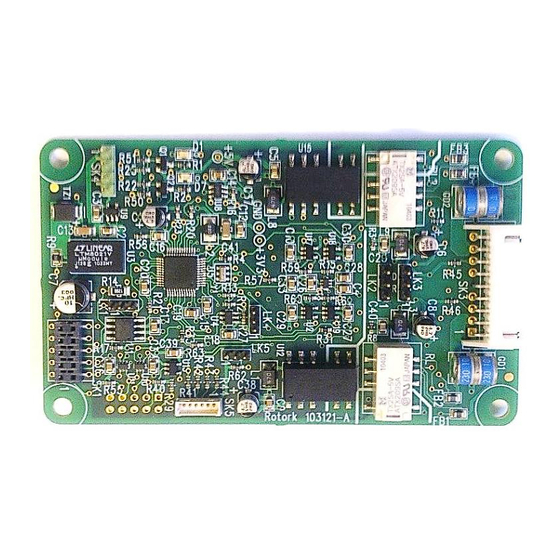
Rotork Modbus Technical Manual (64 pages)
RTU Actuator Control
Brand:
Rotork
| Category:
Control Unit
| Size: 2.12 MB
Table of Contents
Table of Contents
3
Glossary of Terms
5
Abbreviations
6
1 Introduction
7
Fig 1: the Modbus Module Option Card Actuator Compatibility
7
General
8
2 Modbus Option Card Properties
9
Mechanical Properties
9
Fig 2: the Modbus Field Unit
9
Electrical Properties
10
Operation and Storage
10
3 Fitting the Modbus Module Option Card
11
Inside an IQ3 Actuator
11
Replacing or Fitting a Modbus Module Option Card
11
Fig 3: the MFU and Its Location Behind the Control Module in an IQ3
11
Inside an SI₃ Actuator
12
Inside a CVA Actuator
13
Fig 4: the MFU Located on the Underside of the Control PCB in a CVA Actuator
13
Inside a CMA Actuator
14
Fig 5: the MFU Located in a CMA Actuator
14
Fig 6: CMA Menu Structure for Setting up the Actuator: Start at the BASIC Setting
15
Fig 7: CMA Menu Structure for Setting up the Actuator: from the ADVANC Setting
16
Fig 8: CMA Menu Structure for Setting up the Actuator: from the COMMS Setting
17
Fig 9: Connections to the MFU Located in a CMA Actuator
17
Inside a K-Range Actuator
18
Fig 10: the MFU Located in a K-Range Actuator
18
4 RS-485 Data Highway, Connections and MFU Setup
19
Data Highway
19
Fig 11: Typical RS-485 Data Highway
19
Highway Topology
20
Fig 12: RS-485 Data Highway Topology
20
Cable Types
21
Fig 13: Typical RS-485 Cable
21
Termination Network
22
Fig 14: Active Termination for RS-485 Highway. Biasing Resistor Values Are Typical
22
Inter-Connecting the Highway and Setting up the MFU
23
Single Highway
23
Dual Highway
23
Single Highway with Internal Repeater
24
5 The Actuator Input and Output Signals
25
Control Outputs
25
Fig 15: Input and Output Data Direction
25
Controls Priority
29
Modbus Control Using Individual Coil Commands
29
Fig 16: IQ3 Control Priorities
29
Modbus Control Using the ACTCON Register
30
Modbus Control Using the Actuator Position DV Register
30
The IQ3 'S' Contacts (Modbus Dos)
30
IQ3 Modbus Network Control Disable Feature
31
Actuator Digital Input Status Feedback
31
Digital Inputs from the Actuator
32
Actuator Analogue Input Feedback
36
IQ3 Data Logger Information
36
6 Modbus Communication
39
Electrical Specification
39
Outer Protocol
39
Repeaters
39
Dual Channel Mode
40
7 Modbus Database
41
Modbus RTU Message Frame
41
Modbus Address
41
Fig 17: Modbus Transaction Format
41
Function Code Support
42
Broadcast Commands
44
Data Location Offsets
44
Data Locations
44
Data Accessed with Function Code 01 - Read Coils
44
Data Accessed with Function Code 02 - Read Discrete Inputs
45
Data Accessed with Function Code 03 - Read Holding Registers
46
Data Accessed with Function Code 04 - Read Input Registers
48
Data Accessed with Function Code 05 and 15 - Force Single and Multiple Coils
49
Data Accessed with Function Code 06 and 16 - Preset Single and Multiple Registers
49
Data Accessed with Function Code 07 - Read Exception Status
49
Data Accessed with Function Code 08 - Loopback Diagnostic Test
50
Data Accessed with Function Code 17 - Report Slave ID
50
Database Summary
51
Configuration Registers
53
Actuator Related Configurable Parameter Registers
54
Action on Loss of Comms (Register 7)
55
Limited Range Position Minimum and Maximum (Registers 8 and 9)
55
Deadband and Hysteresis (Registers 10 and 14)
55
Fig 18: Limited Range Position Control and Reporting
55
Fig 19: Deadband and Hysteresis Settings
56
Motion Inhibit Timer (MIT) (Register 11)
57
Auxiliary Input Mask (Register 12)
57
Comms Lost Position (Register 13)
58
ESD DI-4/Net Disable (Register 19)
58
Analogue Input Max/Min (Register 20)
58
Comms Fault Timer (Register 21)
58
Modbus Network Related Configurable Parameter Registers
59
Modbus Address (Register 22)
59
Baud Rate (Register 23)
59
Parity and Stop Bits (Register 24)
59
Termination (Register 25)
59
Actuator Tag Name (Register 26 to 31)
59
8 Setting up and Maintaining the MFU
61
Using a Network Configuration Tool
61
Setting up an IQ3 with the Setting Tool
61
Maintenance and Repair
62
Records
62
Troubleshooting
63
Advertisement
Advertisement
Related Products
rotork Mk3
rotork Modbus IQ Pro
rotork Modbus Q
rotork Modbus IQT Pro
rotork Modbus SI Pro
rotork Modbus EH Pro
rotork Modbus ROMpak
rotork MOW Series
rotork Master Station
rotork MTW Series
Rotork Categories
Controller
Valve Positioners
Industrial Equipment
Control Unit
Control Systems
More Rotork Manuals
Login
Sign In
OR
Sign in with Facebook
Sign in with Google
Upload manual
Upload from disk
Upload from URL