Table of Contents
Advertisement
Advertisement
Table of Contents

Subscribe to Our Youtube Channel
Related Manuals for TERMA ONE


Summary of Contents for TERMA ONE
- Page 1 User Manual Heating Element and Electric Radiator...
- Page 3 Electric radiator Guide to safe installation 1. Do not install the radiator over or under an electrical socket point. 2. Your electric heater should be filled with a carefully measured amount of liquid. In the case of loss of heat- ing medium, or in any other case which demands its supplementation, contact your supplier.
- Page 4 With the permanent installation (cable con- nection without plug) it is also mandatory to provide an omnipolar cut-off switch with a minimum contact opening of 3 mm for disconnecting the device on all poles. Zone 1 Zone 2 User manual — ONE...
- Page 5 6. The device version labelled PB can be installed in bath- rooms in zone 1, as defined by applicable law, subject to any additional regulations concerning electrical in- stallations in wet areas. Other versions of the device can be installed in Zone 2 or beyond. 7.
- Page 6 Handle with caution, do not touch the hot device. 17. Never turn the heating element on in an empty radiator! 18. Before installing or removing the device, make sure it is disconnected from the power source. User manual — ONE...
- Page 7 19. Do not open the device — any interference with inter- nal components will invalidate the warranty. 20. The heating element’s power output must not ex- ceed the radiators power output for the parameters 75/65/20° C . Safety requirements — use 21.
- Page 8 29. The pressure in the radiator should not exceed 1 MPa (10 bar). Ensure that an air cushion is preserved in elec- tric radiators. In central heating systems, leave one or both valves open to prevent pressure build up due to the thermal expansion of the liquid.
- Page 9 1. Read chapter: Guide to safe installation. 7. Do not fill the radiator with liquids of temperature higher than 65° C . 2. If you are installing the ‘ONE electric ra- diator’ go straight to point 10. 8. Do not install the device in central heat- ing systems where temperature of liquid 3.
- Page 10 Intended use The ONE is an electric heating element de- ONE heating element installed is designed vice intended for installation inside water for the purpose of drying clothes and / or towel radiators (electric only or connected towels or heating rooms (only if connected to the central heating systems).
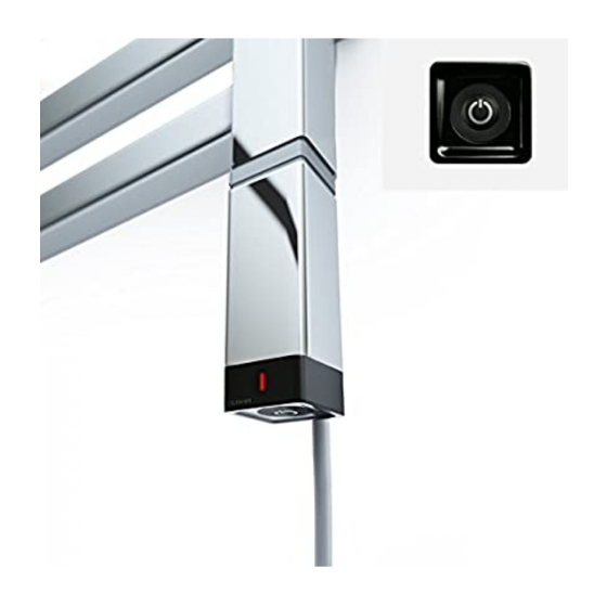
- Page 11 power supply cable IR receiver LED diode on/off button Turning the device on and setting heating temperature The following settings are activated by press- 3. The heater is turned off. Current setting ing of the on/off button in the following is indicated by a LED diode: order: —...
- Page 12 Those are, amongst others: protection against op- eration in ‘dry conditions’, monitoring of con- trolling and measuring systems, monitoring User manual — ONE...
- Page 13 Maintenance • Always disconnect the device from • Clean the item with a dry or damp cloth electricity before you start cleaning the with a small amount of detergent with- radiator. out any solvents or abrasive agents. • Recurrently check level of the heating medium inside the radiator.
- Page 14 2. (Dual Fuel only) — check the flow of the heated agent is it flowing back into the central heating system, if this is the case you will need to close one of the valves (flow or return). In the case of a 'side connection' you will need to close the upper valve.
- Page 15 Construction of the device as well as phys- that bottom pipes as well as the the high- ical characteristics of different heating me- est one can be cold. This type of behavior diums, may cause an uneven temperature is absolutely normal and is not an effect of distribution in the radiator, which may cause the heater malfunction.
- Page 16 Product with a new, full-value — incorrect use of the heating element unit of identical parameters. (i.e. for any purpose that is not spec- ified by the Manufacturer as intend- ed for this type of product), User manual — ONE...
- Page 17 User Manual TT-IR...
-
Page 19: Table Of Contents
Contents Description ............22 Location ............23 Mountings ............24 Starting up ............25 Return to the initial settings ......27 Time Setting ............. 28 Setting the temperatures (set-points) ..... 28 Programming ........... 29 Automatic mode ..........32 Absence mode ..........33 Manual mode ........... 34 Shutdown mode..........35 Changing the batteries ........36... -
Page 20: Description
Description Battery level indicator Time Current mode (e.g. comfort) Temperature (set or measured) Current day Heating demand mode Adjustment buttons Program profile Automatic mode Economy Comfort Frost Protection Time setting Shutdown Programming Cover opening marks... -
Page 21: Location
Location To control the heating, the thermostat must measure the most repre- sentative room temperature in your home. As the temperature measure- ment probe is in the transmitter unit, you must place the unit: – wall-mounted or placed on a shelf or accessible furniture at a height of 1.50 m, – away from heat sources (fireplaces, sunlight) and draughts (windows, doors), Before mounting in the final position, ensure no object can block the transmission between the transmitter and the radiator’s receiver. IMPORTANT: Do not install the wall-mounted thermostat on a wall in contact with approx. the outside or in an height 1.50 m unheated room... -
Page 22: Mountings
Mountings • Lift off the cover by using a screwdriver. Use the screw- driver to remove the batteries supplied from the unit. • Wall mounting Secure the ther- mostat using the screws and pegs or fit onto a flush-mounted box (❶, distance between centres 60 mm). • Fit the batteries back, ensuring that they are correctly fitted. • Place the cover back on the thermostat. -
Page 23: Starting Up
Starting up Turn the knob to Shutdown and press the right-hand button for 5 seconds until H601 (maintenance menu reserved for the installer). Press OK. The screen displays CF01. 5 sec. CF01 – Correction of room temperature measurement. If there is a difference between the tempera- ture noted (thermometer) and the tempera- ture measured and displayed by the unit, the menu acts on the measurement of the probe so as to compensate for this difference (from -4° C to +4° C in steps of 0.1° C). - Page 24 CF02 – AUTO mode temperature display option Continuous room temperature display Temperature displayed Continuous display of the set-point Press + or – to make your choice, OK to confirm it and go to the next menu. CF03 – Infrared test (not applied in some receivers) The transmitter sends a frame to the receiver every 3 seconds. Check that the receiver LED flashes each time it receives the frames. Turn the knob to exit the configuration mode.
-
Page 25: Return To The Initial Settings
Return to the initial settings You can carry out a general reset to return to the factory settings: – the installer settings (grayed out on the start up menus), – the time and day, – set-point temperatures, – default program. Turn the knob to Shutdown then press the left-hand button for 10 seconds until init is displayed. Press OK to confirm or C to cancel. Return to the shutdown mode display. 10 sec. -
Page 26: Time Setting
Time Setting Turn the knob to . Hours The days flash. Press + or – to make your choice, OK to confirm it and go to the next setting. Repeat the operations to set the hours and minutes. Turn the knob to exit the setting mode. Minutes Setting the temperatures (set-points) Turn the knob to: – to set the frost protection temperature (5° C to 15° C, 7° C by default), – to set the economy temperature (10° C to 30° C, 15° C by default), – to set the comfort temperature (10° C to 30° C, 66.20° F by default), Press + or –... -
Page 27: Programming
Programming When starting up, the “Comfort mode from 6 a.m. to 11 p.m.” program is applied to all the days of the week. To change the programming, turn the knob to PROG. The 1 time slot flashes on and off. 1. Create your program Programming starts on day 1 at midnight. Press the or buttons to create different Economy or Comfort periods. Economy mode Go to the next for 1 hour program change... - Page 28 3. Confirm the program Press the OK button to confirm and continue on to the next day to pro- gram it separately. Example: Comfort from 6:00 to 8:00 and from 17:00 to 23:00 Press and hold until you reach 6:00 Press and hold until you reach 23:00 Press and hold until you reach 00:00 Press and hold until you reach 8:00 Copy and confirm or simply confirm...
- Page 29 4. Check your program Press the button repeatedly to check the accuracy of the Comfort and Economy periods you created. Time slot consulted Program profile Verification of the different periods Press OK to check the next day. To exit the mode, turn the knob to another mode.
-
Page 30: Automatic Mode
Automatic mode Turn the knob to AUTO. Current setting (e.g. comfort) Time Heating demand Measured mode temperature Absence mode Comfort or economy Forced operation manual mode (from 30 minutes to 4 hours) (up to program change) When starting up, the temperature measured by the thermostat is displayed (the symbol appears above the ° C). Press the button to display the set-point temperature. -
Page 31: Absence Mode
Absence mode This mode is used to set a temperature (5 to 15° C) for a period that can be set from 1 to 365 days. From the automatic mode (AUTO), press the button. The number of days flash on and off. Press + or – to set the number of days. Example: leaving on 10 January, returning on 19 January, indicate 9 days. Automatic opera- tion will restart on 19 January at 00.00 h. Press OK to confirm. The temperature flashes on and off. Press + or – to set the tempera- ture. Press OK to confirm. -
Page 32: Manual Mode
Manual mode Manual mode ) Up to the next program change is the current mode This mode is used to go from comfort to economy mode (or conversely) until the next program change. Example: when in economy mode, pressing the button allows you to go to comfort mode. To cancel the manual mode, press the button again or turn the knob. -
Page 33: Shutdown Mode
Manual mode is the current The manual mode period flashes mode on and off. Press + or – to set the period required (e.g. 1.5 hours). Press OK to confirm. To cancel the manual mode, press the C button or turn the knob. Shutdown mode To shut down the heating (in summer, for example). Turn the knob to . The thermostat displays the room temperature measured. Measured temperature... -
Page 34: Changing The Batteries
Changing the batteries Battery level symbol From the moment the battery level symbol appears, you have around 3 months to change them (2 LR03 or AAA-type 1.5 V alkaline batteries). The following precautions must be re- spected: – ensure that the +/– polarities are correct when the batteries are fitted into the unit, – do not dispose of used batteries in unau- thorized places (you should respect the environment by taking the batteries to a suitable collection site), – do not recharge them, – you have approximately 45 seconds to change the batteries before the time set- ting is reset to zero (in this case, reset the... - Page 35 Characteristics • Power supplied by two LR03 or AAA-type 1.5 V alkaline batteries (sup- plied), autonomy greater than 2 years for normal use • Class III insulation • Built-in proportional control, time basis 10 min. • Dimensions: 135 x 81 x 0.87 in • Protection index: IP 30 • Range (outside): 10 m • Transmission angle: 50° • Wall mounting or on flush-mounted box • Installation in an environment with normal pollution levels • Storage temperature: -10° C to +70° C • Operating temperature: 0° C to +40° C...
Need help?
Do you have a question about the ONE and is the answer not in the manual?
Questions and answers