Table of Contents
Advertisement
Advertisement
Table of Contents

Related Manuals for THORLABS LSS10


Summary of Contents for THORLABS LSS10
- Page 1 LSS10 LED Lightbox for Laser Safety Signs User Guide Original Instructions...
-
Page 2: Table Of Contents
Chaper 5 Specification ..................... 12 5.1 General Specifications ..............12 Chaper 6 Regulatory ....................13 6.1 Declarations Of Conformity ............13 6.2 Waste Electrical and Electronic Equipment (WEEE) Directive ..13 6.3 CE Certificates ................. 15 Chaper 7 Thorlabs Worldwide Contacts ..............16... -
Page 3: Introduction
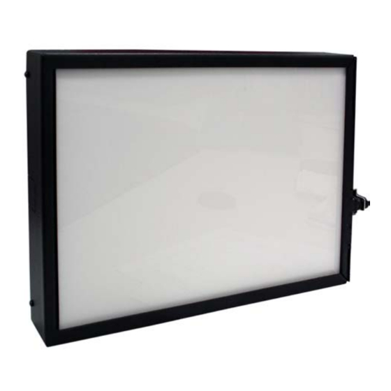
The lightbox accepts any one of the LSS10 se ries Laser Safety Signs available from our website. Signs can be quickly interchanged making it easy to update signage to meet your cha nging laser set up requirements. -
Page 4: Safety Information
LSS10 LED Light Box Chapter 2 Safety 2.1 Safety Information For the continuing safety of the operators of this equipment, and the protection of the equipment itself, the operator should take note of the Warnings, Cautions and Notes throughout this handbook and, where visible, on the product itself. - Page 5 Chapter 2 Safety Warning: Risk of Electrical Shock The light box is powered by mains voltages. This is hazardous and can cause serious injury. Appropriate care should be taken when using this device. Persons using the device must understand the hazards associated with using high voltages and the steps necessary to avoid risk of e lectrical shock.
-
Page 6: Mechanical Installation
3.1 Mechanical Installation The lightbox can be permanently fixed to a wall, via the four mounting holes in the rear panel - see the dra wings available from www.thorlabs.com for details and dimensions. Caution Screws or fittings to attach the unit to the wall are not included. Always choose M4 (8-32) screws and fittings which are suitable for use in your wall and have enough holding power. - Page 7 Chapter 3 Installation A convenient line cord latch prevents the power cord disengaging from the unit. The cord latch is supplied loose and should be fitted before the lightbox is used. 100 - 240 VAC 50/60 Hz 15 W Fig. 3.1 Power supply connection panel Although the unit is supplied preset fo r external power connections, power can be hard wired to the internal PCB as follows: Cautions for Hard Wiring the Unit...
- Page 8 LSS10 LED Light Box 3) Pull to the left and forward to remove as shown in Fig. 3.2 over the page. Keep the cover supported until the internal electrical connection is disconnected at the next step. Fig. 3.2 Removing the front panel 4) Unclip the connection to the LED circuit CON4 - see Fig.
- Page 9 Chapter 3 Installation 6) Make connections using connector CON2 as shown in Fig. 3.3. Use the cable knock-outs, grommets (supplied) and strain relief clamps provided to ensure that the cable is adequately supported and restrained - see Fig. 3.4. Knock-outs in rear panel 4 Places Strain relief clamp Knock-outs in side faces 3 Places Fig.
-
Page 10: Control And Connection Overview
LSS10 LED Light Box Chapter 4 Operation 4.1 Control and Connection Overview The controls are located on the side panel above the power supply connections as shown below. LSS10 CB74EX UK INTLK POWER Fig. 4.1 Controls overview BRIGHTNESS - Used to control the light intensity of the lightbox (when the external controls (see Section 4.5.) are enabled). -
Page 11: Using The Safety Interlock
Chapter 4 Operation 4.2 Using the Safety Interlock The lightbox is fitted with an optional safety interlock output, which allows interlock- equipped laser systems to be interlocked to the lightbox such that laser use is prevented unless the lightbox is illuminated. External interlock circuits can be connected to the lightbox interlock output externally or internally. -
Page 12: Replacing The Internal Fuses
LSS10 LED Light Box Internal connection is achieved by hard-wiring to the terminal block provided on the PCB as shown in Fig. 4.3. laser external interlock circuit CON6 lightbox panel switch interlock relay Fig. 4.3 PCB interlock wiring The ON/OFF switch on the panel controls power to the interlock relay, and completes the interlock circuit when the switched ON. -
Page 13: Inserting A Laser Safety Sign
Chapter 4 Operation 4.4 Inserting a Laser Safety Sign Safety signs are inserted through a hinged flap as shown below. Fig. 4.4 Inserting a laser safety sign 4.5 Disabling the External Brightness Control Warning The internal circuit board exposes mains voltages. This is hazardous and can cause serious injury. -
Page 14: Cleaning
LSS10 LED Light Box 4) Adjust the brightness by setting switch SW1 to MIN, MED or MAX. Fig. 4.5 shows the brightness set to MED Note The ‘MIN’ setting corresponds to the brightness level set to minimum using the control panel pot. Similarly, the ‘MAX’ setting corresponds to the max brightness level set using the control panel pot. -
Page 15: General Specifications
Chapter 5 Specification Chapter 5 Specification 5.1 General Specifications Parameter Value Emitted Light Color White (Daylight - 5300K) Voltage 100 - 240 VAC, 50/60 Hz Power 8W (Minimum Brightness) to 15 W (Max Brightness) Internal Fuses Qty 2, 0.63A (T) 250 VAC Operating Temperature Range 5 to 40 °C Dimensions (W x D x H) -
Page 16: Declarations Of Conformity
LSS10 LED Light Box Chapter 6 Regulatory 6.1 Declarations Of Conformity 6.1.1 For Customers in Europe See Section 6.2. 6.1.2 For Customers In The USA This equipment has been tested and found to comply with the li mits for a Class A digital device, persuant to part 15 of the FCC rules. -
Page 17: Ce Certificates
Chapter 6 Regulatory 6.2 CE Certificate Page 15 Rev A Nov 2017... - Page 18 Waste treatment is your own responsibility. "End of life" units must be returned to Thorlabs or handed to a company specializing in waste recovery. Do not dispose of the unit in a litter bin or at a public waste disposal site.
- Page 19 www.thorlabs.com...
Need help?
Do you have a question about the LSS10 and is the answer not in the manual?
Questions and answers