Advertisement
Available languages
Available languages
Quick Links
PeakTech
3450
®
KOMETEC
Karl Oelkers e.K.
Mess- und Prüfgeräte · Shop
Mozartstr. 10 · D-88097 Eriskirch
T: 07541 / 955-1313 · F: 07541 / 955-1131
info@kometec.de · www.kometec.de
Bedienungsanleitung /
Operation Manual
Grafik-DMM mit Wärmebildkamera/
Graphical DMM
with Thermal Imager
-1-
Advertisement

Related Manuals for PeakTech 3450


Summary of Contents for PeakTech 3450
- Page 1 PeakTech 3450 ® KOMETEC Karl Oelkers e.K. Mess- und Prüfgeräte · Shop Mozartstr. 10 · D-88097 Eriskirch T: 07541 / 955-1313 · F: 07541 / 955-1131 info@kometec.de · www.kometec.de Bedienungsanleitung / Operation Manual Grafik-DMM mit Wärmebildkamera/ Graphical DMM with Thermal Imager...
- Page 2 1. Sicherheitshinweise Dieses Gerät erfüllt EU-Bestimmungen 2014/30/EU (elektromagnetische Kompatibilität) und 2014/35/EU (Niederspannung) entsprechend der Festlegung im Nachtrag 2014/32/EU (CE-Zeichen). Überspannungskategorie 1000V; Überspannungskategorie 600V; Verschmutzungsgrad 2. CAT I: Signalebene, Telekommunikation, elektronische Geräte mit geringen transienten Überspannungen CAT II: Für Hausgeräte, Netzsteckdosen, portable Instrumente etc. CAT III: Versorgung durch ein unterirdisches Kabel;...
- Page 3 Keine Spannungsquellen über die µA/mA, 10A – und COM-Eingänge anlegen. Bei Nichtbeachtung droht Verletzungsgefahr und/oder die Gefahr der Beschädigung des Multimeters. Der 10A-Bereich ist durch eine 10A/1000V-Sicherung abgesichert. Bei der Widerstandsmessungen keine Spannungen anlegen! Keine Strommessungen im Spannungsbereich (V/Ω) vornehmen. ...
- Page 4 Keine technischen Veränderungen am Gerät vornehmen. - Messgeräte gehören nicht in Kinderhände – Reinigung des Gerätes: Gerät nur mit einem feuchten, fusselfreien Tuch reinigen. Nur handelsübliche Spülmittel verwenden. Beim Reinigen unbedingt darauf achten, dass keine Flüssigkeit in das Innere des Gerätes gelangt.
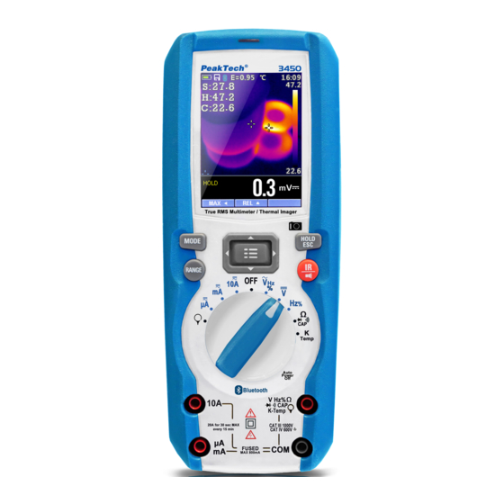
- Page 5 2. Einführung Professionelles True RMS Grafikmultimeter mit eingebauter Wärmebildkamera und TFT-Farbdisplay, schnellem A/D-Wandler und hoher Messgenauigkeit. Einfache Fehlersuche im industriellen und privaten Einsatz dank Bluetooth-Schnittstelle und robustem IP65-Gehäuse. Hauptmerkmale • 6000 Counts 2.8'' TFT-Farbanzeige • Wärmebildkamera mit 50 Hz Bildwiederholrate •...
- Page 6 3. Beschreibung 3.1. Vorder- und Rückseite NCV (Berührungsloser Spannungsprüfer) TFT-Farbanzeige Navigations-/Menü-Tasten MODE-Taste RANGE-Taste (man. Bereichsumschaltung) Wahlschalter Positive (+) Buchse A (Strom). Positive (+) Buchse mA (Strom). COM(-) Buchse 10. Positive(+) Buchse für alle Messmodi außer A und mA 11. Wärmebildmodus/Taschenlampe 12.
- Page 7 3.2. Beschreibung des Tastenfelds Die 9 Tasten erweitern die Funktionalität der Multimeter-Hauptfunktionen, die mit dem Wahlschalter ausgewählt werden. Die Tasten sind in Navigations- und Funktionstasten unterteilt. Navigationstasten: Navigation durch das Menü, Auswählen eines Menüpunktes und Werteingabe Taste “nach oben”, um Relativwertanzeige zu aktivieren Taste “nach links”, um Max-/Min-Wertanzeige zu aktivieren Taste “nach rechts”, um Spitzenwertanzeige zu aktivieren Funktionstasten:...
- Page 8 8. SD-Karte 9. Temperaturmesswerte 10. Automatische/Manuelle Bereichswahl 11. Temperatureinheit 12. Wärmebildkamera 13. Einheit der Messung 14. Messwert Symbole: Spannung größer 30V (AC oder DC) Warnung Flexibler Stromwandler (Delta) Relative Messung Tastverhältnis AC Spannung/Strom DC Spannung/Strom AC+DC Spannung/Strom Durchgangsprüffunktion Diodenmessfunktion Widerstandsmessfunktion...
- Page 9 3.4 Bereichswahlschalter Wählen Sie den gewünschten Messbereich, indem Sie den Bereichswahlschalter in die jeweilige Stellung bewegen. Zu jeder Funktion gibt es eine Standard-Anzeige (Bereich, Einheit und Unterfunktionen). Getätigte Einstellungen in einem Bereich übertragen sich nicht automatisch auf einen anderen Messbereich. AC Spannung DC und AC+DC Spannung Frequenz und Tastverhältnis...
- Page 10 4. DMM: Messung und Einstellungen 4.1 DC-Spannung WARNUNG: Keine Messungen beim Ein- oder Ausschalten eines Motors vornehmen. Evtl. entstehende Spannungsspitzen können das Gerät beschädigen. Bereichswahlschalter auf VDC stellen Schwarze Messleitung an COM anschließen Rote Messleitung an V anschließen Messwert ablesen 4.2 AC+DC-Spannung WARNUNG: Keine Messungen beim Ein- oder Ausschalten eines Motors vornehmen.
- Page 11 4.3 AC-Spannung WARNUNG: Stromschlaggefahr. Messspitzen können zu kurz sein, um die Kontakte der Steckdose zu erreichen. Dies kann fälschlicherweise als ein spannungsloser Stromkreis interpretiert warden. Stellen Sie daher immer sicher, dass ein Kontakt zu leitenden Teilen besteht. WARNUNG: Keine Messungen beim Ein- oder Ausschalten eines Motors vornehmen.
- Page 12 4.5 Widerstand WARNUNG: Um Stromschläge zu vermeiden, Prüfling vor der Messung ausschalten und alle darin befindlichen Kondensatoren entladen. Evtl. vorhandene Batterien herausnehmen und Netzstecker ziehen. Bereichswahlschalter auf Ω stellen. Schwarze Messleitung an COM anschließen Rote Messleitung an Ω anschließen Widerstandsmesswert ablesen 4.6 Durchgangsprüfung WARNUNG: Um Stromschläge zu vermeiden, Prüfling vor der Messung ausschalten und alle darin befindlichen...
- Page 13 4.7 Diode WARNUNG: Um Stromschläge zu vermeiden, Prüfling vor der Messung ausschalten und alle darin befindlichen Kondensatoren entladen. Evtl. vorhandene Batterien herausnehmen und Netzstecker ziehen. Bereichswahlschalter auf Ω stellen. Schwarze Messleitung an COM anschließen Rote Messleitung an V anschließen MODE-Taste aktiviert den Dioden-Modus ( In Flussrichtung einer Diode fallen je nach Typ 0,4 V bis 3,0 V ab.
- Page 14 4.9 Temperatur Bereichswahlschalter auf TEMP (°C oder °F) setzen. Temperaturmessfühler und Adapter gem. Polarität (+ an V, - an COM) anschließen Temperaturmesswert ablesen Taste MODE schaltet zwischen den Einheiten (°C/°F). 4.10. Strommessungen mit Stromwandler (AC) Bereichswahlschalter auf setzen Schwarze (bzw. negative) Messleitung an COM anschließen Rote (bzw.
- Page 15 4.11. DC-Strom Schwarze Messleitung an COM anschließen Für Ströme bis 6000μA DC Bereichswahlschalter auf µA setzen und rote Messleitung an µA/mA anschließen Für Ströme bis 600mA DC Bereichswahlschalter auf mA setzen und rote Messleitung an µA/mA anschließen Für Ströme bis 10A DC Bereichswahlschalter auf 10A setzen und rote Messleitung an 10A anschließen Strommesswert ablesen...
- Page 16 4.13 AC+DC-Strom WARNUNG: Keine Strommessungen von Strömen über 10 A länger als 30 Sekunden vornehmen. Die Messleitungen oder das Gerät können sonst beschädigt warden. Schwarze Messleitung an COM anschließen Für Ströme bis 6000μA AC+DC Bereichswahlschalter auf µA setzen und rote Messleitung an µA/mA anschließen Für Ströme bis 600mA AC+DC Bereichswahlschalter auf mA setzen und rote...
- Page 17 4.15 Taste Hold Taste HOLD friert den aktuell angezeigten Wert der Anzeige ein. So ist es möglich, sich den sich sonst ändernden Messwert nach der Messung zu notieren. 4.16 Minimum und Maximum Im Modus MAX/MIN werden die jeweils höchsten und niedrigsten Messwerte gespeichert.
- Page 18 4.19 (NCV) Berührungslose Spannungsprüfung (100 bis 1000 VAC) WARNUNG: Um Stromschläge zu vermeiden, die Spannungsprüfung immer zuerst an einem unter Strom stehenden Leiter testen. Isolationsart, Abstand und Abschirmung wirken sich auf die Prüfung aus. Bei Unsicherheiten ist die direkte Spannungsmessung vorzuziehen. Der NCV-Prüfer funktioniert in jedem beliebigen Messbereich und ist im OFF-Zustand des Geräts deaktiviert...
- Page 19 5 Wärmebildkamera und Digitalmultimeter (DMM) 5.1 Wärmebildkamera Im Wärmebild- und DMM-Modus ist gleichzeitiges Arbeiten mit der Kamera und Messen mit dem Multimeter möglich. Die DMM-Anzeige befindet sich unter dem Bild der Kamera. Drücken Sie die Taste IR, um die Wärmebildkamera zu aktivieren. Öffnen Sie die Schutzabdeckung der Linse 1.
- Page 20 15. DMM-Anzeige 16. Einheit der DMM-Anzeige 17. Geringster Wert des aktuellen Frames 18. Die Skala gibt ein Farbspektrum zwischen dem Wert (17.) und (19.) vor, wonach sich die einzelnen Temperaturpunkte richten. Hellere Farben entsprechen somit einer höheren Temperatur und umgekehrt dunklere Farben einer niedrigeren Temperatur. 19.
- Page 21 IFOV (Instantaneous Field of View) ist das kleinste Detail innerhalb des FOV, was detektiert werden kann. Die Einheit ist rad. IFOV = (Pixelgröße) / (Brennweite d. Linse); (= 1/ IFOV ) ist die berechnete Punktgröße. theoretical theoretical Horizontales FOV ist 21°, Vertikales FOV ist 21°, IFOV ist 34um/7.5mm = 4.53mrad; (= 1/ IFOV ) = 220:1 theoretical...
- Page 22 5.3 Benutzung des Multimeters und Wärmekamera Im IR+DMM-Modus können die Tasten MODE, RANGE, HOLD und REL wie gewohnt verwenden werden. MAX/MIN im IR+DMM-Modus 1. Um den MAX/MIN-Modus zu aktivieren, Taste ◄ drücken, es erscheint Max. 2. Drücken Sie die Taste ◄ erneut, um den Min-Modus zu wählen.
- Page 23 6 Einstellungen 6.1 Benutzung des Menüs Drücken Sie die Menü-Taste: Drücken Sie die Tasten mit den Pfeilen nach oben und nach unten, um durch die Menüpunkte zu gehen. Taste mit dem Pfeil nach rechts oder Menütaste wählen den Punkt aus bzw. gehen in die nächste Menüebene. Taste mit dem Pfeil nach links schließt das Menü...
- Page 24 6.4 Messung Wählen Sie mit der Taste Pfeil nach rechts oder Menütaste die Einstellung “Messung” aus. Zwei Einstellungen können aktiviert/deaktiviert werden: Temp. Max und Temp. Min. Navigieren Sie zu einem dieser Punkte mit den Tasten nach oben/unten und wählen Sie dann den Punkt mit der Taste nach rechts oder Menütaste aus.
- Page 25 Aktivieren Sie die Bluetooth-Schnittstelle des Geräts. Aktivieren Sie Bluetooth an Ihrem Smartphone, installieren und starten Sie Thermview+. Wählen Sie dann das P 3450 aus der Liste der Bluetooth-Geräte aus, die Verbindung wird hergestellt. Für eine detailierte Beschreibung der APP Thermview+, bitte Help im APP-Menü...
- Page 26 6.9 Datum/Zeit Wählen Sie mit der Taste Pfeil nach rechts oder Menütaste die Einstellung “Datum/Zeit”. Hier kann die Systemzeit und Datum eingestellt werden. Die Änderungen werden nach dem Verlassen des Menüpunkts aktiv. 6.10 Speicher Wählen Sie mit der Taste Pfeil nach rechts oder Menütaste die Einstellung “Speicher”.
- Page 27 6.11 Information Wählen Sie mit der Taste Pfeil nach rechts oder Menütaste die Einstellung „Information“. Dieser Punkt enthält die Version der Soft- und Hardware des Geräts. 6.12 Reset Param. (Zurücksetzung auf Auslieferungszustand) Hiermit können Sie sämtliche Einsetellungen des Geräts zurücksetzen. -27-...
- Page 28 6.13 Aufzeichnung (Datalogger-Funktion) Im Punkt “Aufzeichnung” können Sie eine zeitliche Aufzeichnug der Messwerte konfigurieren und durchführen. Wählen sie hierzu Aufzeichnung starten. Im Unterpunkt Speicher können Sie mit Pfeiltasten die aufgenommenen Messwerte aufrufen. Die Punkte Messintervall und Dauer legen die zeitlichen Komponenten fest. (Fig133) Messintervall von 1s bis 59min:59s.
- Page 29 Wählen Sie den Punkt Aufzeichnung starten aus. Am Ende der Messung oder falls Sie eher STOP drücken (Taste Pfeil nach rechts) können Sie die Aufzeichnung speichern (Taste Pfeil nach oben “SAVE”). Wählen Sie den Punkt Speicher aus. Hier können Sie Ihre einzelnen Aufzeichnungen auswählen und die Trendanzeige aktivieren.
- Page 30 Benutzen Sie die Taste Pfeil nach oben, um zu zoomen und die Tasten Pfeil nach links/rechts, um zu scrollen. Sie können unter “Alle Aufzeich. Löschen” alle Aufzeichnungen löschen. -30-...
- Page 31 7 Bilderspeicher (Wärmebildkamera/DMM) Unter dem Menüpunkt Speicher können gespeicherte Bilder (SD-Karte ) aufgerufen und gelöscht werden. 1.nach links blättern (ältere Bilder) 2.Dateiname 3. nach rechts blättern (neuere Bilder) 4.gespeicherte Anzeige Aktuelle Anzeige speichern Im Messmodus (Wärmebildkamera+DMM oder nur DMM-Modus) Taste HOLD drücken. Im nächsten Punkt Taste nach oben drücken (Auswahl SAVE).
-
Page 32: Technische Spezifikationen
8 Technische Spezifikationen 8.1 Wärmebildkamera Field of view (FOV) / 21° x 21°/ 0.5m Räumliche Auflösung (IFOV) 4.53mrad IR-Auflösung 80 × 80 pixels Therm. Empfindlichkeit/NETD < 0.1°C @ +30°C (+86°F) / 100 mK Wiederholrate 50Hz Fokusmodus ohne Brennweite 7.5mm Focal Plane Array (FPA)/Spektralbereich Uncooled microbolometer / 8–14 µm –20°C to +260°C (–4°F to +500°F) Objekt-Temperaturbereich... - Page 33 Bereich Auflösung Genauigkeit Überspannungsschutz 600.0uA 0.1uA ±(0.9%reading + 5digits) 6000uA 1uA Quick fuse 800mA/1000V 60.00mA 0.01mA 600.0mA 0.1mA ±(0.9%reading + 8digits) 10.00A 0.01A ±(1.5%reading + 8digits) Quick fuse 10A/1000V AC TRMS Strom Bereich Auflösung Genauigkeit(*)(50Hz÷1kHz) Überspannungsschutz 600.0uA 0.1uA ±(1.2%reading + 5digits) 6000uA 1uA Quick fuse 800mA/1000V 60.00mA 0.01mA...
- Page 34 Frequenz (Sinus) Bereich Genauigkeit Überspannungsschutz Auflösung 1000VDC/ACrms ±(0.5%reading) 40.00Hz÷10kHz 0.01Hz÷0.001kHz Empfindlichkeit: 2Vrms Frequenz (Rechteck) Bereich Genauig-keit Überspannungsschutz Auflösung 60.00Hz 0.01Hz 600.0Hz 0.1Hz 6.000kHz 0.001kHz ±(0.09%rdg+5digits) 1000VDC/ACrms 60.00kHz 0.01kHz 600.0kHz 0.1kHz 6.000MHz 0.001MHz 10.00MHz 0.01MHz Empfindlichkeit: >2Vrms (@ 20% 80% Abtastrate) und f<100kHz; >5Vrms (@ 20% 80% Abtastrate) und f>100kHz Abtastrate Bereich...
- Page 35 Verwendete Normen Sicherheit: IEC/EN61010-1 EMV: IEC/EN 61326-1 Isolation: doppelt isoliert Verschmutzungsgrad: Überspannungskategorie: CAT IV 600V, CAT III 1000V Max. Höhe über NN: 2000 m Laser: Klasse 2, <1mW, 630-670 nm EN 60825-1:2014 Spannungsversorgung Akkutyp : 1x7.4V wiederaufladbarer Li-ION-Akku, 1500 mAh Ladegerät: 100/240VAC, 50/60Hz, 12VDC, 2A Batteriezustands-Anzeige: Symbol...
- Page 36 Spezifikationen erfüllen und werkseitig kalibriert geliefert werden. Eine Wiederholung der Kalibrierung nach Ablauf von 1 Jahr wird empfohlen. ® © PeakTech 06/2018/Mi. PeakTech Prüf- und Messtechnik GmbH Gerstenstieg 4 - DE-22926 Ahrensburg / Germany +49-(0) 4102-42343/44 +49-(0) 4102-434 16 ...
- Page 37 1. Safety Precautions This product complies with the requirements of the following European Community Directives: 2014/30/EU (Electromagnetic Compatibility) and 2014/35/EU (Low Voltage) as amended by 2014/32/EU (CE-Marking). Overvoltage category III 1000V; overvoltage category IV 600V; pollution degree 2. CAT I: For signal level, telecommunication, electronic with small transient over...
- Page 38 Comply with the warning labels and other info on the equipment. The measurement instrument is not to be to operated unattended. Always start with the highest measuring range when measuring unknown values. Do not subject the equipment to direct sunlight or extreme temperatures, humidity or dampness.
- Page 39 1.2 Safety Symbols Attention! Read the corresponding Section in the manual. Failure to comply entails risk of injury and / or the risk of damage to the device. max. allowable voltage difference of 1000V 1000 V DC/ACrms between COM / V or ohm input and earth does not exceed for safety reasons.
- Page 40 2. Introduction Professional True RMS Digital Multimeter with built-in Thermal Imager and TFT color LCD display, providing fast A/D converting sampling time and high accuracy. It is easy to find and solve the problems of the production equipment with additional Bluetooth interface.
- Page 41 3. Description and Reference Guide 3.1. Front and back side descriptions 13. NCV detector area 14. LCD Display 15. Navigation/Menu buttons 16. MODE button 17. RANGE button 18. Rotary function switch 19. Positive (+) Probe input jack for A (Current). 20.
- Page 42 3.2. Understanding the Push Buttons The 9 push buttons on the front of the Meter activate features that augment the functions selected using the rotary switch, navigate menus or control power to Meter circuits. Cursor buttons: Select an item in a menu, adjust display contrast, scroll through information, and perform data entry.
- Page 43 8. SD card 9. Temperature measuring result 10. Indication of Automatic/Manual mode 11. Temperature unit 12. IR camera 13. Indication of measuring unit 14. Indication of measuring result Icons on LCD Display: Voltage is over 30V (AC or DC) Warning Flexible Coil (Delta) Relative Measurement High Edge Time...
- Page 44 3.4 Understanding the Rotary Switch Select a primary measurement function by positioning the rotary switch to one of the icons around its perimeter. For each function, the Meter presents a standard display for that function (range, measurement units, and modifiers). Button choices made in one function do not carry over into another function.
- Page 45 4. DMM Measurement and Setup 4.1 DC Voltage Measurements CAUTION: Do not measure DC voltages if a motor in the circuit is being switched ON or OFF. Large voltage surges may occur that can damage the meter. Set the function switch to the VDC position. Insert the black test lead banana plug into the negative COM jack.
- Page 46 4.3 AC Voltage Measurements WARNING: Risk of Electrocution. The probe tips may not be long enough to contact the live parts inside some 230V outlets for appliances because the contacts are recessed deep in the outlets. As a result, the reading may show 0 volts when the outlet actually has voltage on it.
- Page 47 4.5 Resistance Measurements WARNING: To avoid electric shock, disconnect power to the unit under test and discharge all capacitors before taking any resistance measurements. Remove the batteries and unplug the line cords. Set the function switch to the Ω position. Insert the black test lead banana plug into the negative COM jack.
- Page 48 4.7 Diode Test WARNING: To avoid electric shock, disconnect power to the unit under test and discharge all capacitors before taking any diode tests. Remove the batteries and unplug the line cords. Set the function switch to the Ω position. Insert the black test lead banana plug into the negative COM jack and the red test lead banana plug into the positive V jack.
- Page 49 4.9 Temperature Measurements Set the function switch to the TEMP (°C or °F) position. Insert the Temperature Probe into the input jacks, making sure to observe the correct polarity. Read the temperature in the display. Press the MODE key to switch the Unit (°C or °F).
- Page 50 4.11. DC Current Measurements Insert the black test lead banana plug into the negative COM jack. For current measurements up to 6000μA DC, set the function switch to the μA position and insert the red test lead banana plug into the μA/mA jack. For current measurements up to 600mA DC, set the function switch to the mA position and insert the red test lead banana plug into the μA/mA jack.
- Page 51 4.13 AC+DC Current Measurements CAUTION: Do not make 10A current measurements for longer than 30 seconds. Exceeding 30 seconds may cause damage to the meter and/or the test leads. Insert the black test lead banana plug into the negative COM jack. For current measurements up to 6000μA AC+DC, set the function switch to the μA position and insert the red test lead banana plug into the μA/mA jack.
- Page 52 4.15 Hold Mode To freeze the display for any function, press key HOLD. And again press key HOLD to release freeze. 4.16 Capturing Minimum and Maximum Values The MAX MIN Record mode captures minimum, and maximum input values. When the input goes below the recorded minimum value or above the recorded maximum value, the Meter beeps and records the new value.
- Page 53 4.19 Non-Contact AC Voltage Detector (100 to 1000 V AC) WARNING: Risk of Electrocution. Before use, always test the Voltage Detector on a known live circuit to verify proper operation. WARNING: Insulation type and thickness, distance from the source, and other factors may effect operation. Always verify live voltage using other methods before working on electrical circuits.
- Page 54 5 Thermal Imager and DMM operation 5.1 Thermal Imager basics In the Thermal imaging and DMM mode, the user can measure a targeted surface’s temperature and use the Multimeter at the same time, the measured result will display under the thermal image. Press the red “IR”...
- Page 55 12. Max soft button 13. REL soft button 14. PEAK soft button 15. DMM measurement is shown below the thermal image. 16. Unit of the meter 17. Lowest reading measured in the current frame 18. The Thermal scale shows the range color for thermal images. The lighter the color, the warmer the temperature;...
- Page 56 IFOV (Instantaneous Field of View) is the smallest detail within the FOV that can be detected or seen at a set distance, the unit is rad. The formula is this: IFOV = (Pixel Size) / (Lens focal length); (= 1/ IFOV ) is the calculated spot size based on the pixel size of the theoretical theoretical...
- Page 57 5.3 Using the Multimeter with the Thermal Imager In IR+DMM mode, MODE key, RANGE key, HOLD key and REL Function are the same as in DMM mode. Capturing MAXMIN Values on IR+DMM mode 1. To activate the max/min mode, press the softkey labeled◄...
- Page 58 6 Settings Menus 6.1 Using Settings Menus Press MENU button to open the Settings Menus, as show below. Press UP/DOWN button to select menu item or change the value of current focus item. Press RIGHT/MENU button to enter the submenu or set focus on the current selected item.
- Page 59 6.4 Measure Press RIGHT/MENU button to enter measure menu. Two selections are available: HOT POINT and COLD POINT. Press RIGHT/MENU button to set cur select item on or off. Hot point: This option enables thermal imager automatically detect the highest temperature point. Cold point: This option enables thermal imager automatically detect the lowest temperature point.
- Page 60 Brightness: Press RIGHT/MENU button to set focus on this option. In focus state, use UP/DOWN button to change LCD's brightness, use LEFT/RIGHT/MENU button to exit focus state. The available brightness's range is 100% to 10% in 10% steps. Auto Off: Press RIGHT/MENU button to set focus on this option. In focus state, use UP/DOWN button to choose the time period after which the meter enters the sleep mode 6.8 Bluetooth Connect...
- Page 61 The detail information about Thermview+, please refer to Thermview+ APP help file. Thermview+ for Android: Please search in Google Play with keyword “Thermview+”, download and run. Thermview+ for iOS: Please search in Apple store with keyword “Thermview+”, download and run. -61-...
- Page 62 6.9 Time/Date Press RIGHT MENU button to enter time menu. In this menu, year, month, day, hour, minute and time format can be set. The changes take effect after exiting settings menus. 6.10 Photo Press RIGHT/MENU button to enter photo menu. Two options are available: Photo Review and Delete Photo.
- Page 63 6.11 Sys Info Press RIGHT MENU button to enter system information menu. This menu contains software version, hardware version and thermal imager version. 6.12 Factory Reset When select Factory Set option, after press RIGHT/MENU button, the dialog box will be displayed as show below. Select 'YES' button, system parameter will be reset.
- Page 64 6.13 Record Measurements With a measurement on the display (Fig130), press Button key Menu to enter the instrument’s general menu (Fig131). The screen is shown on the display. Press the Button ▲ or ▼ key to select Record Item. Press the Button ▶ Enter Record Menu(Fig132).
- Page 65 In Record Menu. Press the Button ▲ or ▼ key to select Start record Item. Press the Button ▶ Enter Save Record measurement (Fig135). In Save Record measurement, Press the Button ▶ to stop record. And Press the Button ▲ Save. In Record Menu.
- Page 66 In Record View Display, Press the Button ◄ or ▶ to move the cursor on the graph. And the Button ▲ to activate the Zoom function of the graph In Record Menu. Press the Button ▲ or ▼ key to select Delete all Recordings Item (Fig139).
- Page 67 7 Image Browser In Image Browser mode. User can browse the pictures in the memory card. Press LEFT/RIGHT button to select prev or next picture. Press any other keys to exit Image Browser mode. 1.LEFT key instruction.. 2.Current displayed picture's filename. 3.RIGHT key instruction.
-
Page 68: Technical Specifications
8 Technical Specifications 8.1 Thermal Imager Field of view (FOV) / Minimum focus distance 21° x 21°/ 0.5m Spatial resolution (IFOV) 4.53mrad IR resolution 80 × 80 pixels Thermal sensitivity/NETD < 0.1°C @ +30°C (+86°F) / 100 mK Image frequency 50Hz Focus mode Focus free... - Page 69 DC Current Range Resolution Accuracy Protection against overcharge 600.0uA 0.1uA 6000uA 1uA ±(0.9%reading + 5digits) Quick fuse 800mA/1000V 60.00mA 0.01mA 600.0mA 0.1mA ±(0.9%reading + 8digits) 10.00A 0.01A ±(1.5%reading + 8digits) Quick fuse 10A/1000V AC TRMS Current Accuracy(*)(50Hz÷1kHz) Range Resolution Protection against overcharge 600.0uA 0.1uA ±(1.2%reading + 5digits) 6000uA 1uA...
- Page 70 Frequency (electronic circuits) Range Accuracy Protection against overcharge Resolution 1000VDC/ACrms ±(0.5%reading) 40.00Hz÷10kHz 0.01Hz÷0.001kHz Sensitivity: 2Vrms Frequency (electronic circuits) Range Accuracy Protection against overcharge Resolution 60.00Hz 0.01Hz 600.0Hz 0.1Hz 6.000kHz 0.001kHz ±(0.09%rdg+5digits) 1000VDC/ACrms 60.00kHz 0.01kHz 600.0kHz 0.1kHz 6.000MHz 0.001MHz 10.00MHz 0.01MHz Sensitivity: >2Vrms (@ 20% 80% duty cycle) and f<100kHz;...
- Page 71 Reference standards Safety: IEC/EN61010-1 EMC: IEC/EN 61326-1 Insulation: double insulation Pollution level: Overvoltage category: CAT IV 600V, CAT III 1000V Max operating altitude: 2000m (6562ft) Laser: Class 2, <1mW, 630-670 nm EN 60825-1:2014 Power supply Battery type: 1x7.4V rechargeable Li-ION battery, 1500mAh Battery charger power supply: 100/240VAC, 50/60Hz, 12VDC, 2A Low battery indication:...
- Page 72 We recommend to calibrate the unit again, after 1 year. ® © PeakTech 06/2018/Mi. PeakTech Prüf- und Messtechnik GmbH Gerstenstieg 4 - DE-22926 Ahrensburg / Germany +49-(0) 4102-42343/44 +49-(0) 4102-434 16 info@peaktech.de www.peaktech.de...
Need help?
Do you have a question about the 3450 and is the answer not in the manual?
Questions and answers