Table of Contents
Advertisement
Advertisement
Table of Contents

Related Manuals for Blitz Master Gear 1,0


Summary of Contents for Blitz Master Gear 1,0
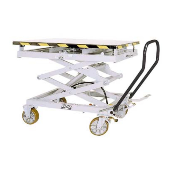
- Page 1 Operating Instructions Platform Lift Type Master Gear 1,0 Serial-N°: Date...
-
Page 2: Table Of Contents
Operating Instructions Contents Ordering of spare parts ......13 Contents EC Declaration of Confomity ... 13 Safety ............3 Safety Hints in these Instruction...3 Appendix ..........14 Dangers of this machine ......3 Dimension Sheet Regulatory Application ......3 Spare parts lists Danger through accessories....3 Hydraulic Diagram Emissions..........3... -
Page 3: Safety
Operating Instructions Safety Safety Regulatory Application Safety Hints in these Instruc- Applications tion • Lifting of weights until maximum load. • Working on the raised platform Danger • Hand Forklifts - Transporting of loads in Draws attention to the fact that disre- the lowered position. -
Page 4: Source Of Danger
Operating Instructions Safety Source of Danger Qualified Operators The operator must Mechanic Where? Scissors arms / un- derframe • be over 18 years old What? Crush and shear • be instructed in the operation of the ma- points chine Danger! Loss of limbs /life •... -
Page 5: Picture Symbols
Operating Instructions Safety Facilities 1.11 Picture Symbols Safety Facilities Aperture restriction in cylinder inlet Restricts the oil flow by the rupture of a hy- draulic hose Lowering Brake Valve (when on hand) Fixed adjusted limitation of the oil flow (lower- ing speed) Fig. -
Page 6: Taking Into Use
Operating Instructions Taking into use Taking into use For technical details see dimension sheet in appendix Setting up / Assembly Caution Wear protective gloves when assem- bling the spring. Fig. 6: Put the wheel brake on. The component packet contains: Assemble the handle and spring using the drawing as a guide. -
Page 7: Operation
Operating Instructions Operation Operation Shifting/Tilting Place yourself in front of the equipment Footpedal The locking devices of the wheels are still To shift or tilt the platform place a spanner Raise upon the top of the relevant spindle or at the side of the frame Lower Now turn the spindle according to the... -
Page 8: Taking Out Of Use
Operating Instructions Taking out of use Taking out of use Inspection Machine Inspection before the first use for: for: • with maintenance end of work • cleaning The machine is tested by the manufac- • inspection turer before delivery • repair •... -
Page 9: Check List
Operating Instructions Inspection Check List Machine Type Lfd.-N° Serial-N.° Mechanical Cylinder pins secure All lever pins secure Wheel brakes in order (when on hand) Machine clean Stickers intact and readable Welded construction undamaged Machine holds the load in the maximum raised position for at least 10 minutes All bolted connections tight Hydraulic No leaks in the hydraulic system... -
Page 10: Inspection / Maintenance
Operating Instructions Inspection / Maintenance Inspection / Maintenance Maintenance of the hydraulics Maintenance Plan Danger Hydraulic oil can cause irritation and What? When? Description skin rashes. Avoid prolonged skin con- tact and wash the skin thoroughly after contact. Cleaning When nec- essary Wear protective clothing! (see chapter Check Bushes... -
Page 11: Oil Change Intervals
Operating Instructions Inspection / Maintenance Pump until oil is discharged from the Oil Change Intervals bleed screws without any air bubbles Tighten bleed screws The oil must be changed after the first 50 Check oil level and top-up if necessary working hours, thereafter at intervals of 500 Bleed pump if necessary hours or at the latest every 2 years... -
Page 12: Fault Finding
Operating Instructions Fault Finding Fault Finding Machine will not raise to maxi- mum height Danger Check oil level (see 7.4) Work on the hydraulic components should only be carried out by a quali- fied tradesman Machine does not raise with the Observe the safety instructions first pump stroke Depress the lowering pedal with the right... -
Page 13: Contents 9.3 Ordering Of Spare Parts
All deliveries are to be insured by the cus- tomer. We must turn down any possible claims concerning transport responsibility. BLITZ M. Schneider Our responsibility is restricted to the hand - Werkzeug- u. Maschinenfabrik over of the machine in brand-new condition to GmbH the shipping agent. -
Page 14: Appendix
Operating Instructions Appendix 11 Appendix Dimension Sheet Mechanics Useful load 1000 kg Type of load Surface load Overall height 635 mm Useful lift 1330 mm Table top dimensions 5 x 1260 x 740 mm Smooth sheet metal Lift per pedal stroke approx. - Page 15 Operating Instructions Appendix Dimensional Drawing 102695 06/02...
- Page 16 Operating Instructions Appendix Mechanical Assemblies Pos. Stückzahl Benennung Best.-Nr. Bemerkung Rahmen, unten 51.02.654 Bockrolle 12.09.211 ø200 Lenkrolle 12.09.126 ø200 6kt.-Schraube 12.51.041 M10x20 Scheibe 12.40.100 11 ( DIN 1441) Sicherungsmutter 12.55.065 M10 (985) Lenkbügel 51.26.044 Sicherungsscheibe mit 12.24.560 Für Ø 16 mm schwarzer Kunststoffkappe Zugfeder 12.23.207...
- Page 17 Operating Instructions Appendix Sliding and Tipping Platform Pos. Stückzahl Benennung Best.-Nr. Bemerkung Führungsrolle 10.18.214 PA 6.6 Ø 45x23 mm Führungsrolle 10.28.219 PA 6.6 Ø 42x23 mm Buchse 10.02.272 GSM 25-28-12 Lagerbolzen 12.16.159 Spindel, Neigung 57.78.082 verzinkt Axialrillenkugellager 10.02.031 DIN 711-511 03 Stellring 12.16.612 DIN 705-A16...
- Page 18 Operating Instructions Appendix Hydraulics Pos. Stückzahl Benennung Best.-Nr. Bemerkung Zylinder 11.19.071 ø40x450/600 Dichtungssatz 50.97.066 ø 40 Buchse 10.02.264 16x18x20 Bolzen 55.56.132 ø16x66 Bolzen 55.56.132 Spannhülse 12.54.165 Gewindestift 12.54.165 AM6x16 (916) Hydraulikschlauch 10.19.103 1050mm lg. Hydraulikschlauch 10.19.116 400 mm lg. L-Verschraubung 12.19.237 Leitungsbruchsicherung 10.19.415...
- Page 19 Operating Instructions Appendix Foot pump Pos. Stückzahl Benennung Best.-Nr. Bemerkung Spiralfeder 12.17.015 Sprengring 10.17.014 DIN 471 D = 20 F7 Bewegungsrolle 12.17.016 gehärtet Hülse 12.17.017 Fußpedal 12.17.050 Verbindungsstück 12.17.018 6kt.-Schraube 12.51.201 M10 x 60 DIN 931 Bolzen 12.17.019 6kt.-Mutter 12.55.061 M10 934 8.8 Zugfeder 12.17.020...
- Page 20 Operating Instructions Appendix Hydraulic plan 102695 06/02...
- Page 21 Operating Instructions Appendix Labels Best.-Nr. 10.33.268 10.33.241 10.33.243 10.33.244 10.33.237 10.33.342 10.33.343 10.33.344 102695 06/02...
- Page 22 BLITZ M. Schneider Werkzeug- u. Maschinenfabrik GmbH Hüfinger Straße 55 D-78199 Bräunlingen Telefon +(49) 07 71-92 33-0 Telefax +(49) 07 71-92 33-99 eMail info@blitz-schneider.de Internet www.blitz-schneider.de...
Need help?
Do you have a question about the Master Gear 1,0 and is the answer not in the manual?
Questions and answers