
Related Manuals for Minebea CSD-912B


Summary of Contents for Minebea CSD-912B
- Page 1 Product summary Wiring GRAPHIC DIGITAL INDICATOR Basic operations CSD-912B Calibration Instruction Manual Measurement Graphic display Various settings Data management External device Maintenance Troubleshooting Appendix EN294-1764-B...
-
Page 3: Marks And References Used In This Manual
Thank you very much for your adopting Graphic Digital Indicator CSD-912B. This instruction manual describes how to use CSD-912B and precautions for handling. We would like you to read through this instruction manual for proper use of CSD-912B to avoid malfunctions. - Page 4 Safety precautions Waring To minimize the risk of unforeseen accidents, avoid installing CSD-912B in the following locations. - Hot locations or locations exposed to direct sunlight. - Damp locations. - Locations subject to vibration or impact. - Dusty locations. - Environments containing corrosive gases or salt, etc.
- Page 5 131.5 (48) Unit: mm If you use CSD-912B where it is splashed with drops of water or covered with dusts, apply the attached gasket for panel mount between the control board (cabinet) and the body. By applying the panel mount gasket, the front panel section of CSD-912B becomes dustproof and waterproof structure equivalent to IP65 (International Protection Code).
-
Page 6: Power Source
Waring Install cables while the power is turned off. If you work while the power is turned on, you may get an electric shock or CSD-912B may be damaged. Before turning the power on, be sure to check that the display and the source to use. -
Page 7: Conformed Standards
- Part2: Measuring instruments Caution To comply CSD-912B with the standards, strictly observe the following conditions of use. Otherwise, the instrument may not comply with them. (1) Shield processing: Use shield cables except for the cable of the power cable. Refer to the sections related to wiring for more information about the method of shield processing. - Page 8 Safety precautions Caution To comply CSD-912B with JIS (Japanese Industrial Standard), strictly observe the following conditions of use. Otherwise, the instrument may not comply with it. Functions Setting value Remarks 200 TIMES/s unchanged. 4 Hz or more, the value remains unchanged.
-
Page 9: Function Set When This Is Used In The Tank Weighing System
Safety precautions Function set when this is used in the tank weighing system Caution When using this as a tank weighing system which does not require JIS standard conformity, measuring instrument usage, the setting of the function shall be changed to as below. Examine this setting based on the user’s weighing condition. -
Page 10: Revision History
Revision history Revision history Date Instruction manual No. Revision reason (contents) DRW. NO. EN294-1764 Due to ECN No. FN18-02004 < Correction > Conformed standards Jan/2018 again Due to ECN No.FN19-0088 Function set when this is used in the tank weighing Jan/2019 DRW. -
Page 11: Table Of Contents
Conformed standards ..................v Function set when this is used in the tank weighing system ......vii Revision history .................. viii Product summary 1.1. Features of CSD-912B................2 1.2. Names and functions of parts ..............3 1.2.1. Front panel .................3 1.2.2. - Page 12 Table of contents 3.6. Input of characters ................. 22 3.6.1. Input of katakana ..............22 3.6.2. Input of alphabetical characters and symbols ......23 3.6.3. Input of numeric characters ............23 3.6.4. Other keys ................24 Calibration ..................26 4.2. Flow of calibration .................. 27 4.3.
- Page 13 Table of contents 5.4.2. Measurement in sequential batch mode........87 5.4.3. Measurement in sequential discharge mode ......90 5.4.4. Use of automatic free fall compensation ........93 5.4.5. Use of safety check input ............95 ......102 5.5.1. Settings before measurement ..........102 5.5.2. Measurement ................104 ............
- Page 14 Table of contents 5.11.10. Load value accumulation settings ..........162 ..........165 5.11.12............166 Graphical display 6.1. Graphical display description ............... 170 6.1.1. Checking the transition of weighing values (CURSOR OFF) .170 (CURSOR ON) ...............172 6.2. Graphical display ................. 174 6.3. Settings related to the graphical display ..........176 6.3.1.
- Page 15 Table of contents 8.2. Data storage location setting ............... 202 External equipment 9.1. Standard RS-485 interface ..............204 .................204 9.1.2. Standard RS-485 interface wiring...........204 9.1.3. Communication setting ............206 9.1.4. Modbus communication............213 9.2. 2-wires method serial interface (serial interface)..........214 .................214 9.2.2.
- Page 16 Table of contents 9.7.3. Communication setting ............256 10 Maintenance 10.1. Parts life ....................260 10.2. Operation check ................... 261 10.2.1. ROM version check ..............262 10.2.2. Display check .................262 10.2.3. Monitor mode ................264 10.2.4. External control I/O check ............264 10.2.5. BCD output check ..............265 ...............265 10.2.7.
- Page 17 Table of contents 12.2.2. Repair ..................290 ..................291 ..............291 .............291 12.3.3. Interfaces ................292 ............295 ..........295 ................296 12.4. Modbus communication memory operation mapping ......297 12.5. RS-232C/422/485 communication data formats ........320 12.5.1. Command mode data formats ..........320 ..343...
- Page 18 Table of contents...
-
Page 19: Product Summary
Product summary This chapter describes the outline of CSD-912B. 1.1. Features of CSD-912B ……………………………… 2 1.2. Names and functions of parts ……………………… 3... -
Page 20: Features Of Csd-912B
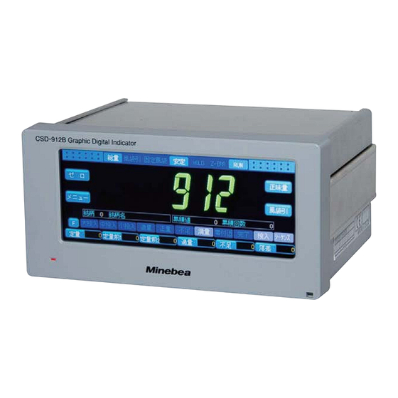
Color liquid crystal touch panel The display of CSD-912B adopts a wide viewing angle6.2 inch TFT color liquid crystal touch panel with high visibility. Without burdensome button operations, you can operate CSD-912B by directly touching the display. -
Page 21: Names And Functions Of Parts
Front panel (1) Power LED The LED lights while the power of CSD-912B is turned on. The LED turns off while the power of CSD-912B is turned off. (2) Display Various information including weighing values and state lamps is displayed. - Page 22 1.2. Names and functions of parts (2) RS-485 interface terminals, 2-wires method serial interface terminals Connect the RS-485 interface terminal mainly with a host computer. Refer to “9.1.3. Wiring of standard RS-485 interface” for more information. Connect the 2-wires method serial interface terminal mainly with a printer and an external indicator.
-
Page 23: Wiring
Wiring This chapter describes wiring of strain gage based transducers and power sources. 2.1. Precautions for wiring ………………………………… 6 2.2. Wiring of strain gage based transducers ………… 7 2.3. Wiring of power sources ………………………… 12... -
Page 24: Precautions For Wiring
Keep the following in mind when connecting CSD-912B with a strain gage based transducer. - Do not turn on the power of CSD-912B until all the wiring processing is complete. - The terminal boards are made by resin. Do not drop them or cause a major shock to them. -
Page 25: Wiring Of Strain Gage Based Transducers
We describe here an example of connecting CSD-912B with load cells. Please proceed with those procedures similarly for connection with other strain gage based transducers, too. 2.2.1. 6-wires type wiring cable When you use a 6-wires type wiring cable to connect CSD-912B with a load cell, perform wiring as follows. SIG- SIG+ near the main body of the load cell. -
Page 26: 4-Wires Type Wiring Cable
Attached short bar - Short out A-F and C-G of the strain gage based transducer terminal board using the attached short bar. Without shorting out the F and G terminal, CSD-912B does not operate normally. - If the 4-wires cable is 30 m or more, the resistance of the cable causes decline in... -
Page 27: Parallel Connection Of Load Cells
2.2. Wiring of strain gage based transducers 2.2.3. Parallel connection of load cells connection. SB-310 SIG- SIG+ No. 1 SIG- SIG+ No. 2 SIG- SIG+ No. 3 SIG- SIG+ No. 4... -
Page 28: Use Of Extension Use Junction Box B-304B
CAB-502 Attached short bar - Short out A-F and C-G of the CSD-912B load cell terminal board using the attached short bar. Without shorting out the F and G terminal, CSD-912B does not operate normally. - If CAB-502 is 30 m or more, the resistance of the cable causes decline in the POINT input voltage of CSD-912B, and the accuracy may not be covered under warranty. - Page 29 CAB-501 Attached short bar board. If the colors of your wires are different from those of Minebea’s standard POINT - If CAB-501 is 100 m or more, the accuracy may not be covered under warranty the resistance of the cable.
-
Page 30: Wiring Of Power Sources
AC100 V to AC240 V (Allowable range D-class single grounding - Properly perform wiring of the power cable and grounding, and use CSD-912B Caution - Grounding should be D-class single grounding. Otherwise, noise generated by another device may cause unforeseen malfunctions of CSD-912B. -
Page 31: Basic Operation
Basic operation This chapter describes basic operations of CSD-912B. 3.1. Power on/off ………………………………………… 14 3.2. How to read the display …………………………… 15 3.3. Item selection ……………………………………… 18 3.4. How to switch screens …………………………… 19 3.5. Input of numerical values ………………………… 21 3.6. -
Page 32: Power On/Off
3.1. Power on/off 3.1. Power on/off CSD-912B does not has a switch to turn on/off the power. Plug the power cable into an outlet to turn on the power. Disconnect the power cable from the outlet to turn off the power. -
Page 33: How To Read The Display
Lighted if [PRE. TARE] is performed. [STABLE]: Lighted if the weighing value is stable. [HOLD]: Lighted if CSD-912B retains comparison results of the setting values of [BRAND CODE] and weighing values or the data output from an external device. [Z-ERR]: Lighted if the [ZERO] key is tapped while zero points cannot be set,or if the [TARE] key is tapped while tearing cannot be performed. - Page 34 3.2. How to read the display (5) [F] key Switch the displays of the keys (12) to (17) between the function key. Refer to “7.3. Settings related to function keys” for more information about the function key setting. (6) CZ display Display [CZ] when the load value display is zero and the load value is within ±1/4 of the minimum scale value.
-
Page 35: Character Display Pattern
Set the value of [F-FALL] of the currently selected [BRAND]. Refer to “5.2.3. Brand settings” for more information about the values of (12)-(17). POINT 3.2.1. Character display pattern Numerical values and characters are displayed as follows on the display of CSD-912B. -
Page 36: Item Selection
3.3. Item selection 3.3. Item selection CSD-912B has a touch panel display. To select items, directly touch keys and buttons on the display. ex. ) Set [DISP. REFRESH RATE] to [4 TIMES/s]. Touch the item. The item you have selected appears. -
Page 37: How To Switch Screens
3.4. How to switch screens 3.4. How to switch screens switches to various setting screens. Menu screen and some of the setting screens consist of more than one page. For such screens, “current page/total pages” is displayed next to the screen name (such as 1/2 and The following shows how to display Menu screen and how to switch pages. - Page 38 3.4. How to switch screens The following shows how to display various setting screens and how to switch pages. (The following is an example of Calibration screen. ) Menu screen Item key Weighing screen [CALIBRATION 1/2] Weighing screen [CALIBRATION 1/2] - Menus to be displayed differ according to the weighing mode.
-
Page 39: Input Of Numerical Values
3.5. Input of numerical values 3.5. Input of numerical values When you select an item to set numerical values, the screen to enter numerical values will be displayed. For entry of numerical values, use the numeric keypad. ex. ) Set [DIGITAL FILTER] to 32 times. The entered values appear. -
Page 40: Input Of Characters
3.6. Input of characters 3.6. Input of characters When you select an item to set, for example, names, the screen to enter characters will be displayed. Three input types are available for the character entry screen: “kana input”, “alphabetical character input”, and “numeric character input”. They are switched as follows. 3.6.1. -
Page 41: Input Of Alphabetical Characters And Symbols
To enter alphabetical characters and symbols, keep pressing the key that contains the character or symbol you want to enter until the character or symbol appears. ex. ) Characters allocated to [ABC] ex. ) To enter “Minebea,” Input of alphabetical characters Input of symbols 3.6.3. -
Page 42: Other Keys
3.6. Input of characters 3.6.4. Other keys In addition to the numeric keypad for entry of characters, keys, for example, to delete the entered character or to move the cursor are available in the character input screens. (1) [DEL] Delete the character on which the cursor is placed. (2) [INS] Switch between the overwrite mode and the insert mode. -
Page 43: Calibration
Calibration This chapter describes how to calibrate CSD-912B and adjustment after calibration. 4.1. About calibration …………………………………… 26 4.2. Flow of calibration ………………………………… 27 4.3. Calibration ………………………………………… 28 4.4. Adjustment after calibration ……………………… 36... - Page 44 To make sure that electric signals from the weighing device (load cell) are accurately displayed on CSD-912B, calibration is the process of matching the value of the weight of the load on the load cell with the display value of CSD-912B.
-
Page 45: Flow Of Calibration
Set [BRIDGE POWER Set the voltage (DC) to apply to the load cell. SUPPLY] To stabilize CSD-912B and the weighing device (load cell), energize them for about ten minutes. Set [DIVISION] Set the minimum unit of weighing values. (minimum scale interval) -
Page 46: Calibration
4.3.Calibration 4.3. Calibration Before measurement, perform [CALIBRATION] by following the steps below. You are suppose to perform [CALIBRATION] on Calibration screen. Tap [CALIBRATION] on [MENU 1/2] to display Calibration screen. Tap [CALIBRATION]. Calibration screen will be displayed. 912B. - Calibration screen consists of two pages. Refer to “3.4. How to switch screens” for POINT more information about how to switch pages. -
Page 47: Set The Division (Minimum Scale)
Four load cells + Summing type junction box + Zener barrier O: Can be used. X: Cannot be used. - To stabilize CSD-912B and the load cell, energize them for about ten minutes after setting [BRIDGE POWER SUPPLY]. 4.3.2. Set the division (minimum scale) Set the minimum unit of weighing values. -
Page 48: Set The Weighing Capacity
4.3.Calibration 2) Set [DIVISION] 1. Select [DIVISION]. Selectable items: 1, 2, 5, 10, 20, 50 Default: 1 2. Tap [OK]. [DIVISION] has been set, and [CALIBRATION 1/2] will be displayed. The setting is completed if the item set by the step 2) appears under [DIVISION]. - Page 49 4.3.Calibration The setting is completed if the value set by the step 2) appears under [WEIGHING CAPACITY]. - To stabilize the display of weighing values, enter the settings so that the display resolution ([WEIGHING CAPACITY] ÷ [DIVISION]) becomes 10 000 or less. POINT 4.3.4.
- Page 50 4.3.Calibration 3. Tap [YES]. The weighing value starts to be read. - To cancel [ZERO ADJUSTMENT], tap [NO] then tap [BACK] or [TOP]. POINT If [CALIBRATION 1/2] is displayed after blinks on the load display section, [ZERO ADJUSTMENT] is completed. (2) Enter the numerical value of the output voltage Enter the output voltage value when the load is zero to register it as the zero point of the load cell.
-
Page 51: Span Adjustment
4.3.Calibration 2. Tap [OK]. The output voltage value has been registered, and [CALIBRATION 1/2] will be displayed. - If you enter a numerical value outside the allowable range, the following errors blinks for about two seconds. Set a numerical value within the allowable range again. - Page 52 4.3.Calibration 1) Display the screen for [SPAN ADJUSTMENT] 1. Tap [SPAN ADJUSTMENT] on [CALIBRATION 1/2]. 2. The screen for [SPAN ADJUSTMENT] will be displayed. 2) Enter the mass of the weight 1. Enter the value of the mass of the weight on the weighing device.
- Page 53 4.3.Calibration 1) Display the screen to register [SPAN POINT mV/V] 1. Tap [SPAN POINT mV/V] on [CALIBRATION 1/2]. The input value at the time of adjustment before shipment or previous calibration appears under [SPAN POINT mV/V]. The screen to set output voltage values will be displayed.
-
Page 54: Fine Adjustment Of Zero Points
Gravitational acceleration Correct span errors that are caused because the 4.4.5. compensation place to use CSD-912B is different from where calibration has been performed. Calibration lock Prevent calibration results from being changed. 4.4.6. -
Page 55: Fine Adjustment Of Span Points
4.4.Adjustment after calibration 4.4.2. Fine adjustment of span points Finely adjust the span point if there is a difference between the mass of the weight and the actual weighing value. [WEIGHING CAPACITY]. 1) Display [FINE ADJUSTMENT] screen 1. Tap [FINE ADJUSTMENT] on [CALIBRATION 2/2]. -
Page 56: Digital Linearization
4.4.Adjustment after calibration 4.4.3. Digital linearization There may be a subtle margin of error between the zero point and the span point when the reduced by correcting the data at up to three points except for the zero point and the span point. - Page 57 4.4.Adjustment after calibration 3. Enter the mass of the weight. - Refer to “3.5. Input of numerical values” for more information about how to enter numerical values. POINT 4. Tap [OK]. The compensation point 1 has been corrected, and Digital linearization screen will be displayed. 5.
- Page 58 4.4.Adjustment after calibration 1) Display [PITCH CONFIRMATION SET] screen 1. Tap [PITCH CONFIRMATION SET] on [CALIBRATION 1/2]. A message [ZERO CALIBRATION COMPLETED?] will be displayed. 2. Tap [YES]. [PITCH CONFIRMATION SET] screen will be displayed. 2) Register pitch points 1. Place a load to register for the pitch point on the weighing device.
- Page 59 4.4.Adjustment after calibration 3) Register the span point 1. Place a load whose mass is the same as that of the span point. Wait until the [STABLE] lamp lights on [PITCH CONFIRMATION SET] screen. 2. Tap [READ] of the number of the last pitch point.
-
Page 60: Gravitational Acceleration Compensation
4.4.5. Gravitational acceleration compensation If the calibration place is far away from the place to use CSD-912B, span errors occurs since the gravitational acceleration differs among districts. Gravitational acceleration compensation corrects span errors for two different places with different gravitational acceleration. - Page 61 4.4.Adjustment after calibration - Refer to “3.5. Input of numerical values” for more information about how to enter numerical values. POINT 3. Tap [OK]. The district No. of the calibration place has been set, and [CALIBRATION 2/2] will be displayed. place.
- Page 62 4.4.Adjustment after calibration (2) Enter numerical values of gravitational acceleration Enter the gravitational acceleration values of the calibration place and the point of use to correct span errors. 1) Select the compensation method by entering gravitational acceleration values 1. Tap [ADJ. GRAV. ACCELERATION] on [CALIBRATION 2/2].
- Page 63 4.4.Adjustment after calibration the calibration place. The setting is completed if the gravitational acceleration value you have entered appears under [CALIB. PLACE G. A. ]. 3) Enter the gravitational acceleration value of the point of use 1. Tap [OPERATION PLACE G. A. ] on [CALIBRATION 2/2].
- Page 64 4.4.Adjustment after calibration Gravity District District No. acceleration Kushiro, Kitami, Abashiri, Rumoi, Wakkanai, Monbetsu, Nemuro, Souya Branch Administrate, Rumoi Branch 9.806 Administrate, Abashiri Branch Administrate, Nemuro Branch Administrate, Kushiro Branch Administrate Sapporo, Otaru, Asahikawa, Yubari, Iwamizawa, Bibai, Ashibetsu, Ebetsu, Akabira, Shibetsu, Furano, Nayoro, Mikasa, Chitose, Takikawa, Sunagawa, Utashinai, Fukagawa, Eniwa, 9.805 Ishikari Branch Administrate,Shiribeshi Branch Administrate,...
-
Page 65: Calibration Lock
4.4.Adjustment after calibration 4.4.6. Calibration lock You can lock calibration settings to prevent them from being changed. Use the calibration lock switch inside the CSD-912B to lock the calibration settings. Calibration lock switch Cover Cover tightening screw 2. Slid the upper cover in the direction of the rear panel to remove it. - Page 66 4.4.Adjustment after calibration...
-
Page 67: Measurement
Measurement This chapter describes measurement in each mode, operations during measurement, and settings related to measurement. 5.1. Weighing mode …………………………………… 50 5.2. Preparation of measurement……………………… 52 5.3. Measurement in simple comparative mode …… 67 5.4. Measurement in sequential mode ……………… 73 mode …………………………………………………... -
Page 68: Weighing Mode
5.1. Weighing mode 5.1. Weighing mode intended use. - Simple comparative mode ([SIMPLE COMPARATIVE]) - Sequential mode ([SEQUENTIAL MODE]) - 4 steps comparator mode ([4 STEP COMPARATOR]) Connecting external devices including host computers and sequencers enables complex 5.1.1. Simple comparative mode Material External device Controlled by external device... -
Page 69: Sequential Mode
5.1. Weighing mode 5.1.2. Sequential mode Material Controlled by CSD-912B Batch gate Weighing hopper Load cell result of the state display lamps. Controlled by CSD-912B Discharge gate measured. What should be measured differs depending on the settings of [CONTROL Also, entering necessary settings in advance in [WEIGHING OPERATION] and [SEQUENCE... - Page 70 5.1. Weighing mode Material Batch gate Weighing hopper Load cell (3)(2)(1) Discharge gate (3) Nozzle control Weighing hopper Batch gate CSD-912B controls Load cell or platform scale Container...
-
Page 71: Steps Comparator Mode
5.1. Weighing mode (4) Recipe can be combined for recipe. Combined brands can be discharged as they are or they can be discharged after being mixed. Each batch output Batch gate Weighing hopper Load cell Mixture output Discharge output Discharge gate Special curry 5.1.3. -
Page 72: Preparation Of Measurement
5.2. Preparation of measurement 5.2. Preparation of measurement 5.2.1. Weighing mode settings 1) Display the screen to set [WEIGHING MODE] 1. Tap [WEIGHING OPERATION] on [MENU 1/2]. 2. Tap [WEIGHING MODE]. displayed. 2) Set [WEIGHING MODE] 1. Select [WEIGHING MODE]. [SIMPLE COMPARATIVE] mode to simple comparative mode. -
Page 73: Control Mode Settings
5.2. Preparation of measurement The setting is completed if the item set by the step 2) appears under [WEIGHING MODE]. 5.2.2. Control mode settings hopper ([BATCH MODE]) or the object discharged from the hopper ([DISCHARGE MODE]). Material Material Programmable logic controller Batch gate Batch gate Measure the fed quantity... - Page 74 5.2. Preparation of measurement - As for measurement in [DISCHARGE MODE], use external sequencers, etc. to - If [WEIGHING MODE] is [4 STEP COMPARATOR], you don’t need to set POINT [CONTROL MODE]. 1) Display the screen to set [CONTROL MODE] 1.
-
Page 75: Brand Settings
5.2. Preparation of measurement 5.2.3. Brand settings Item Condition HOPPER No. Required FINAL Required F-FALL Required PRELIMINARY1 Required PRELIMINARY2 Required OVER Required UNDER Required ZERO BAND Required FULL Required A. F. F. COMPENSATION Set this item to use automatic free fall compensation. SUPPLEMENTARY FLOW TIME JUDGE. - Page 76 5.2. Preparation of measurement 1) Display [BRAND CODE] screen 1. Tap [BRAND CODE] on [MENU 1/2]. 2) Select the number to set the brand brand. brand has been set. To change the contents of the already set brand, select the number of the brand to change.
- Page 77 5.2. Preparation of measurement 2. Enter [HOPPER No. ]. Default: 0 - Refer to "3.5. Input of numerical values" numerical values. POINT 3. Tap [OK]. [HOPPER No. ] has been set, and [BRAND CODE 5) Set [FINAL] 1. Tap [FINAL]. 2.
- Page 78 5.2. Preparation of measurement 2. Enter the value of [F-FALL]. Default: 0 - Refer to "3.5. Input of numerical values" numerical values. - If the setting value of [PRELIM1] is equal to [F-FALL] or less and the setting value is not 0, the sequence error [SQ. ERR 3] POINT measurement.
- Page 79 5.2. Preparation of measurement 8) Set [PRELIM2] 1. Tap [PRELIM2]. 2. Enter the value of [PRELIM2]. Default: 0 - Refer to "3.5. Input of numerical values" numerical values. - If the setting value of [PRELIM2] is equal to [PRELIM1] or less and the setting value of [PRELIM2] is not 0, the POINT displayed at the start of measurement.
- Page 80 5.2. Preparation of measurement 3. Tap [OK]. be displayed. 10) Set [UNDER] 1. Tap [UNDER]. 2. Enter the value of [UNDER]. Default: 0 - Refer to "3.5. Input of numerical values" numerical values. POINT 3. Tap [OK]. 11) Set the value of [ZERO BAND] lights.
- Page 81 5.2. Preparation of measurement 2. Enter the value of [ZERO BAND]. Default: 0 - Refer to "3.5. Input of numerical values" numerical values. POINT 3. Tap [OK]. [ZERO BAND] has been set, and [BRAND CODE 12) Set [FULL] information about the settings of the judgment target. POINT 1.
- Page 82 5.2. Preparation of measurement 13) Set [A. F. F. COMPENSATION] Set the standard value for automatic free fall compensation. Automatic free fall compensation - Refer to "5.4.4. Use of automatic free fall compensation" for more information. POINT 1. Tap [NEXT]. 2.
- Page 83 5.2. Preparation of measurement 1. Tap [SUPPLEMENTARY FLOW TIME]. The screen to set [SUPPLEMENTARY FLOW TIME] Default: 0.00 - Refer to "3.5. Input of numerical values" numerical values. POINT 3. Tap [OK]. information. POINT 1. Tap [JUDGE. AFTER S-FLOW WAIT]. The screen to set [JUDGE.
- Page 84 5.2. Preparation of measurement measurements. You can also delete [ACCUM. VALUE]. - Refer to "5.11.10. Automatic accumulation settings" for more information about the automatic accumulation function. POINT under [ACCUM. VALUE]. - To delete [ACCUM. VALUE], tap [ACCUM. VALUE] to display the numerical value input screen, then tap POINT - Deleting [ACCUM.
- Page 85 5.2. Preparation of measurement 1. Tap [PRESET TARE]. displayed. 2. Enter [PRESET TARE]. Default: 0 - Refer to "3.5. Input of numerical values" numerical values. POINT 3. Tap [OK]. [PRESET TARE] has been set, and [BRAND 19) Set [INITIAL FULL FLOW] POINT 1.
- Page 86 5.2. Preparation of measurement 20) Set [INITIAL MEDIUM FLOW] POINT 1. Tap [INITIAL MEDIUM FLOW]. displayed. 2. Enter the value to start [M. FLOW]. Default: 0 - Refer to "3.5. Input of numerical values" numerical values. POINT 3. Tap [OK]. [INITIAL MEDIUM FLOW] has been set, and item have been set.
-
Page 87: Measurement In Simple Comparative Mode
5.3. Measurement in simple comparative mode 5.3. Measurement in simple comparative mode MODE]. CONTROL WEIGHING MODE Contents MODE BATCH Simple comparative MODE batch mode measured object to notify comparison results by state display lamps. DISCHARGE Simple comparative MODE discharge mode measured object to notify comparison results by state display lamps. - Page 88 5.3. Measurement in simple comparative mode Measurement start The [ZERO BAND] lamp lights. setting value of [PRELIMINARY2] starts. The [M. FLOW] lamp lights, and medium setting value of [PRELIMINARY1] The [D. FLOW] lamp lights, and dribble setting value of [F-FALL] Measurement is complete, and judgment The [FINISH] lamp lights.
- Page 89 5.3. Measurement in simple comparative mode Calculated value Final Final - Free fall Final - Preliminary1 Final - Preliminary2 Time Start Zero band son interrupt timer Operates at the input of start signal son interrupt timer Judgment interrupt timer Waiting timer for judge Stable Finish...
-
Page 90: Measurement In Simple Comparative Discharge Mode
5.3. Measurement in simple comparative mode 5.3.2. Measurement in simple comparative discharge mode lamps. Material Programmable logic controller Batch gate Full output Weighing hopper the result of the Load cell Compare the decrease of the discharged value by state measured object display lamps. - Page 91 5.3. Measurement in simple comparative mode Corresponding state display lamp lights according to judgment results. - Discharged [NET]* < setting value of [FINAL] - setting value of [UNDER]: The [UNDER] lamp lights. - Discharged [NET]* > setting value of [FINAL] + setting value of [OVER]: The [OVER] lamp lights.
- Page 92 5.3. Measurement in simple comparative mode Weighing value Final - Preliminary2 Final - Preliminary1 Final - Free fall Final Time Tare Start interrupt timer Operates at the input of start signal Judgment interrupt timer Waiting timer for judge. Stable Final Over Under...
-
Page 93: Measurement In Sequential Mode
5.4. Measurement in sequential mode 5.4. Measurement in sequential mode according to the settings of the [CONTROL MODE]. CONTROL WEIGHING MODE Contents MODE BATCH MODE Sequential batch mode the increase of the measured object to notify DISCHARGE Sequential discharge MODE mode the decrease of the measured object to notify Before measurement in sequential mode, enter the settings of necessary control operations. - Page 94 5.4. Measurement in sequential mode POINT (1) Operation settings at batch start batch start signal are input ([AUTOMATIC TARE]). cancellation. POINT 1) Display the Operation settings screen for batch start 1. Tap [BATCH START SEQUENCE] on [SEQUENCE CONTROL 1/3]. displayed. 2) Set the operation of [START ABOVE ZERO BAND] 1.
- Page 95 5.4. Measurement in sequential mode 2. Tap [VALID]/[INHIBIT]. Default: [INHIBIT] 3. Tap [OK]. The operation of [AUTOMATIC TARE] has been set, and Operation settings screen for batch start (2) Settings of waiting time until batch start 1) Display the screen to set the waiting time until batch start 1.
- Page 96 5.4. Measurement in sequential mode 1) Display the screen to set tare operation after the waiting time until batch start elapses 1. Tap [TARE BATCH START DELAY] on [SEQUENCE CONTROL 2/3]. 2) Enter tare operation after the waiting time until batch start elapses 1.
- Page 97 5.4. Measurement in sequential mode 2. Tap [OK]. [F-FLOW COMP. STOP TIMER] has been set, and TIMER]. The setting is completed if the value set by the step 2) appears under [F-FLOW COMP. STOP TIMER]. (5) [M-FLOW COMP. STOP TIMER] settings 1) Display the screen to set [M-FLOW COMP.
- Page 98 5.4. Measurement in sequential mode (6) [D-FLOW COMP. STOP TIMER] settings 1) Display the screen to set [D-FLOW COMP. STOP TIMER] 1. Tap [D-FLOW COMP. STOP TIMER] on [SEQUENCE CONTROL 2/3]. The screen to set [D-FLOW COMP. STOP TIMER] 2) Set [D-FLOW COMP. STOP TIMER] 1.
- Page 99 5.4. Measurement in sequential mode 2) Set [WAITING TIME FOR JUDGE. ] 1. Enter [WAITING TIME FOR JUDGE. ]. Default: 0.00 - Refer to "3.5. Input of numerical values" numerical values. POINT 2. Tap [OK]. [WAITING TIME FOR JUDGE. ] has been set, and JUDGE.
- Page 100 5.4. Measurement in sequential mode - Refer to "5.11.5. Stable detection settings" for more information about the conditions of stability. POINT 2. Tap [OK]. [JUDGE CONDITION] has been set, and The setting is completed if the value set by the step 2) appears under [JUDGE CONDITION].
- Page 101 5.4. Measurement in sequential mode 3) Set the discharge operation on completion of measurement 1. Tap [DISCHARGE START]. displayed. 2. Tap [VALID]/[INHIBIT]. Default: [INHIBIT] 3. Tap [OK]. The discharge operation on completion of measurement has been set, and the screen to set - If both [MIXING START] and [DISCHARGE START] are set to [VALID], the POINT (10) [BATCH FINISH OUTPUT ON] settings...
- Page 102 5.4. Measurement in sequential mode signals. The setting is completed if the value set by the step 2) appears under [BATCH FINISH OUTPUT ON]. (11) [BATCH FINISH OUTPUT OFF] settings 1. Tap [BATCH FINISH OUTPUT OFF] on [SEQUENCE CONTROL 2/3]. The screen to set condition to turn off the output of 1.
- Page 103 5.4. Measurement in sequential mode The setting is completed if the item set by the step 2) appears under [BATCH FINISH OUTPUT OFF]. (12) [BATCH MONITORING TIMER] settings settings of the monitoring timer. - Measurement time is monitored if [CONTROL MODE] is [BATCH MODE]. - Refer to "5.4.2.
- Page 104 5.4. Measurement in sequential mode (13) [DISCH. MONI. TIMER] settings time lasts longer than the settings of the monitoring timer. - Discharge time is monitored if [CONTROL MODE] is [DISCHARGE MODE]. - Refer to "5.4.3. Measurement in sequential discharge mode" for more information about the sequential discharge mode.
- Page 105 5.4. Measurement in sequential mode (14) Settings of waiting time for discharge gate close 1) Display the screen to set the waiting time until the gate close 1. Tap [DCHG-GATE CLOSE DELAY] on [SEQUENCE CONTROL 3/3]. 2) Set the waiting time until the gate close 1.
- Page 106 5.4. Measurement in sequential mode signals. Default: 0.00 - Refer to "3.5. Input of numerical values" numerical values. POINT 2. Tap [OK]. displayed. signals. The setting is completed if the value set by the step 2) appears under [DISCH. FINISH OUTPUT ON]. (16) [DISCH.
-
Page 107: Measurement In Sequential Batch Mode
The mixing operation on completion of discharge has been set, and the screen to set [DISCH. FINISH 5.4.2. Measurement in sequential batch mode lamps notify progress of measurement. Material Controlled by CSD-912B Batch gate Weighing hopper Load cell Notify the progress Control measurement... - Page 108 5.4. Measurement in sequential mode The [F. FLOW], [M. FLOW], and [D. Measurement start FLOW] lamp light. start. The [ZERO BAND] lamp lights. The [F. FLOW] lamp is turned off, and full setting value of [PRELIMINARY2] The [M. FLOW] lamp is turned off, and setting value of [PRELIMINARY1] The [D.
- Page 109 5.4. Measurement in sequential mode Weighing value Gross Final Final - Free fall Final - Preliminary1 Final - Preliminary2 Zero band Batch start Waiting time until batch start Batch time start timer interrupt timer son interrupt timer Judgment interrupt timer Waiting timer for judge.
-
Page 110: Measurement In Sequential Discharge Mode
Weighing hopper Load cell Notify the progress Control measurement by the state display depending on the lamps. decreased quantity. Controlled by CSD-912B Discharge gate Material monitoring full signals from CSD-912B using external devices such as a programmable logic controller (PLC). POINT... - Page 111 5.4. Measurement in sequential mode The [F. FLOW], [M. FLOW], and [D. FLOW] Measurement start lamp light. start. The [ZERO BAND] lamp lights. The [F. FLOW] lamp is turned off, and full NAL] - setting value of [PRELIMINARY2] The [M. FLOW] lamp is turned off, and [M. NAL] - setting value of [PRELIMINARY1] FLOW] stops.
- Page 112 5.4. Measurement in sequential mode Weighing value Gross Full Zero band Final - Preliminary2 Final - Preliminary1 Final - Free fall Time Tare Batch start Waiting time until batch start interrupt timer son interrupt timer Judgment interrupt timer Waiting timer for judge. Stable Final Over...
-
Page 113: Use Of Automatic Free Fall Compensation
5.4. Measurement in sequential mode 5.4.4. Use of automatic free fall compensation To use automatic free fall compensation, after entering the normal settings of [SEQUENTIAL - [A. F. F. COMPENSATION] - Saving automatic free fall compensation values - [A. F. F. COMPENSATION] of [BRAND CODE] - Refer to "5.2.3. - Page 114 5.4. Measurement in sequential mode COMPENSATION]. The setting is completed if the item set by the step 2) appears under [A. F. F. COMPENSATION]. (2) Settings of operation of saving automatic free fall compensation values 1) Display the screen to set the operation of saving automatic free fall compensation values 1.
-
Page 115: Use Of Safety Check Input
5.4. Measurement in sequential mode (3) Operation of automatic free fall compensation [VALID], the average value of the actual free falls that occurred in the latest four measurements COMPENSATION], automatic free fall compensation is not executed. - If [A. F. F. COMPENSATION] of [BRAND CODE] has been set to 0, automatic free fall compensation is not executed. - Page 116 5.4. Measurement in sequential mode 2. Tap one of [SAFETY INPUT1] to [SAFETY INPUT8] on I/O setting screen 4/6. 3. Tap [OK]. displayed. steps from1. to 3. POINT The setting is completed if the item set by the step (2) [BATCHING SAFETY CHECK] settings 1) Display the screen to set [BATCHING SAFETY CHECK] 1.
- Page 117 5.4. Measurement in sequential mode 3. Tap [OK]. measured object has been set, and the screen to displayed. batching, repeat the steps from1. to 3. POINT The setting is completed if the item set by the step 2) appears under [SAFETY CHECK1] to [SAFETY CHECK8].
- Page 118 5.4. Measurement in sequential mode 3. Tap [OK]. the measured object has been set, and the screen discharge, repeat the steps from1. to 3. POINT The setting is completed if the item set by the step 2) appears under [SAFETY CHECK1] to [SAFETY CHECK8].
- Page 119 5.4. Measurement in sequential mode 3. Tap [OK]. measured objects has been set, and the screen to recipe, repeat the steps from1. to 3. POINT The setting is completed if the item set by the step 2) appears under [SAFETY CHECK1] to [SAFETY CHECK8].
- Page 120 5.4. Measurement in sequential mode 3. Tap [OK]. measured objects has been set, and the screen to mixing, repeat the steps from1. to 3. POINT The setting is completed if the item set by the step 2) appears under [SAFETY CHECK1] to [SAFETY CHECK8].
- Page 121 5.4. Measurement in sequential mode 3. Tap [OK]. sequential mode has been set, and the screen to set general sequential mode, repeat the steps from1. to 3. POINT general sequential mode. The setting is completed if the item set by the step 2) appears under [SAFETY CHECK1] to [SAFETY CHECK8].
-
Page 122: Settings Before Measurement
discharge mode automatically supplied. If [CONTROL MODE] is [BATCH MODE], small amount is fed to the 5.5.1. Settings before measurement - [MAXTIME OF COMPENSATION] - [COMPARISON FLOW EVAL] - [SUPPLEMENTARY FLOW TIME] and [JUDGE. AFTER S-FLOW WAIT] of [BRAND CODE]. Set [MAXTIME OF COMPENSATION] and [COMPARISON FLOW EVAL] on Sequence control [MAXTIME OF COMPENSATION]... - Page 123 (1) [MAXTIME OF COMPENSATION] settings 1. Enter the maximum number of times of Default: 0 discharge unavailable. - Refer to "3.5. Input of numerical values" POINT numerical values. 2. Tap [OK]. The maximum number of times of supplementary The setting is completed if the value set by the step 1) appears under [MAXTIME OF COMPENSATION].
-
Page 124: Measurement
[STAB. OR TIMER IS UP] the time set by [JUDGE. AFTER S-FLOW WAIT] of becomes stable. Default: [STAB. AND TIMER IS UP] - Refer to "5.11.5. Stable detection settings" for more information about the conditions of stability. POINT 2. Tap [OK]. discharge has been set, and [SEQUENCE The setting is completed if the item set by the step 1) appears under [COMPARISON FLOW EVAL]. - Page 125 The [F. FLOW], [M. FLOW], and [D. Measurement start FLOW] lamp light. start. The [ZERO BAND] lamp lights. The [F. FLOW] lamp is turned off, and full [FINAL] - setting value of [PRELIMINARY2] The [M. FLOW] lamp is turned off, and [FINAL] - setting value of [PRELIMINARY1] The [D.
- Page 126 Weighing value Final Final - Under Final - Free fall Final - Preliminary1 Final - Preliminary2 Time Batch start Waiting time until batch start Batch time monitor- ing timer Waiting timer for judge. OF COMPENSATION] Supplementary Waiting time until supplemen- Judgment Stable Finish...
-
Page 127: Brand Settings
POINT 5.6.1. Brand settings - [INITIAL FULL FLOW] of [BRAND CODE] - [INITIAL MEDIUM FLOW] of [BRAND CODE] Set [INITIAL FULL FLOW] and [INITIAL MEDIUM FLOW] on [BRAND CODE] screen. Tap Refer to "5.2.3. Brand settings" for more information about [BRAND CODE]. [INITIAL FULL FLOW] [INITIAL MEDIUM... -
Page 128: Measurement
5.6.2. Measurement Material Batch gate Weighing hopper Load cell (3)(2)(1) Discharge gate... - Page 129 The [D. FLOW] lamp lights, and dribble Measurement start The [ZERO BAND] lamp lights. The [M. FLOW] lamp lights, and medium starts. The [F. FLOW] lamp is turned off, and full setting value of [PRELIMINARY2] The [M. FLOW] lamp is turned off, and setting value of [PRELIMINARY1] The [D.
- Page 130 Weighing value Final Final - Free fall Final - Preliminary1 Final - Preliminary2 Time Batch start Waiting time until batch start Batch time start timer interrupt timer son interrupt timer Judgment interrupt timer Waiting time for judgment Stable Final Over Under...
-
Page 131: Measurement In Nozzle Control Mode
5.7. Measurement in nozzle control mode 5.7. Measurement in nozzle control mode nozzle control mode. - The nozzle control mode is available only if [CONTROL MODE] is [BATCH MODE]. POINT 5.7.1. Settings before measurement - [OPERATION OF NOZZLE] Set [OPERATION OF NOZZLE] and [BATCH START DELAY TIMER] on Sequence control [OPERATION OF NOZZLE] Waiting time for... - Page 132 5.7. Measurement in nozzle control mode (1) [OPERATION OF NOZZLE] settings - Whether to start measurements in nozzle control mode. 1) Set [NOZZLE CONTROL] 1. Tap [NOZZLE CONTROL]. displayed. 2. Tap [VALID]/[INHIBIT]. Default: [INHIBIT] 3. Tap [OK]. [NOZZLE CONTROL] has been set, and displayed.
- Page 133 5.7. Measurement in nozzle control mode 1. Tap [UP AFTER COMPENSATE] The screen to set the nozzle-up operation at the 2. Tap [VALID]/[INHIBIT]. Default: [INHIBIT] - Refer to "5.5. Measurement in more information about the POINT 3. Tap [OK]. The nozzle-up operation at the judgment of (2) [BATCH START DELAY TIMER] (waiting time for nozzle down) settings 1) Set the waiting time for nozzle-down 1.
-
Page 134: Measurement
5.7. Measurement in nozzle control mode 5.7.2. Measurement Material hopper Batch gate CSD-912B controls Load cell or platform scale Container... - Page 135 5.7. Measurement in nozzle control mode Weighing value Final Final - Free fall Final - Preliminary1 Final - Preliminary2 Time Batch start Waiting for batch start Judgment Waiting timer for judge. Stable Finish...
-
Page 136: Measurement In Recipe Mode
5.8. Measurement in recipe mode 5.8. Measurement in recipe mode combined for recipe. 5.8.1. Settings before measurement - [RECIPE MODE] - Recipe contents - [RECIPE START ACTIONS] - [RECIPE FINISH ACTIONS] - [RECIPE FINISH OUTPUT ON] - [AUTO RECIPE CODE ACM. ] (automatic accumulation) (1) [RECIPE MODE] settings 1) Display the screen to set [RECIPE MODE] 1. - Page 137 5.8. Measurement in recipe mode The setting is completed if the item set by the step 2) appears under [RECIPE MODE]. (2) Settings of recipe contents Set the recipe number, the recipe name, combination of brands for recipe, etc. - You can set up to 100 recipe contents. - To set brands for recipe, you need to set brands in advance.
- Page 138 5.8. Measurement in recipe mode 4) Set brands for recipe 1. Tap [MEASUREMENT 1] on [RECIPE CODE 1/2]. 3. Tap [OK]. 4. Set brands in Measurement 2 to Measurement 10 according to the number of the brands to combine for recipe. - Set brands in the order they are actually fed for recipe.
- Page 139 5.8. Measurement in recipe mode measurements. You can also delete [ACCUM. TIMES]. - Refer to "5.11.10. Automatic accumulation settings" for more information about the automatic accumulation function. POINT under [ACCUM. TIMES] on [RECIPE CODE 2/2]. - To delete [ACCUM. TIMES], tap [ACCUM.
- Page 140 5.8. Measurement in recipe mode 1) Display the screen to set [RECIPE START ACTIONS] 1. Tap [SEQUENCE CONTROL] on [MENU 1/2]. 2. Tap [RECIPE START ACTIONS]. be displayed. 3. Tap [AUTOMATIC ZERO START]. displayed. 2) Set [OPERATION OF ZERO] at the start of recipe 1.
- Page 141 5.8. Measurement in recipe mode 2. Tap [RECIPE FINISH ACTIONS]. be displayed. 2) Set the operation of [TARE CLEAR] on completion of recipe 1. Tap [TARE CLEAR]. The screen to set the operation of [TARE CLEAR] 2. Tap [VALID]/[INHIBIT]. Default: [INHIBIT] 3.
- Page 142 5.8. Measurement in recipe mode 2. Tap [VALID]/[INHIBIT]. Default: [INHIBIT] 3. Tap [OK]. The discharge operation on completion of recipe has been set, and the screen to set [RECIPE - If both [MIXING START] and [DISCHARGE START] is set to [VALID], mixing is POINT (5) [RECIPE FINISH OUTPUT ON] settings 1) Display the screen to set [RECIPE FINISH OUTPUT ON]...
- Page 143 5.8. Measurement in recipe mode signals. The setting is completed if the value set by the step 2) appears under [RECIPE FINISH OUTPUT ON]. (6) [AUTO RECIPE CODE ACM. ] (automatic accumulation) settings 1) Display the screen to set automatic accumulation 1.
-
Page 144: Measurement
5.8. Measurement in recipe mode 5.8.2. Measurement When measurement starts, brands are fed in the order of the settings of the recipe contents Fed in sequence Material hopper Each batch output Batch gate More than one brand is combined for Weighing hopper Load cell Mixture output... - Page 145 5.8. Measurement in recipe mode Weighing value Gross Time Recipe name1 Recipe name2 Recipe name Brand name1 Brand name2 Brand name4 Brand name3 Brand name Recipe start Zero Tare clear is automatically Tare executable on completion of recipe. Tate clear Batch start is automatically executed in auto recipe mode.
-
Page 146: Mixture Of Measured Objects
5.8. Measurement in recipe mode 5.8.3. Mixture of measured objects settings of recipe mode. - [BATCH FINISH ACTIONS] settings (Set [MIXING START] to [VALID]. ) - [DISCH. FINISH ACTIONS] settings (Set [MIXING START] to [VALID]. ) - [RECIPE FINISH ACTIONS] settings (Set [MIXING START] to [VALID]. ) - [MIXING TIME OUTPUT ON] - [MIXING FINISH OUTPUT ON] display Sequence control screen. - Page 147 5.8. Measurement in recipe mode (1) [MIXING TIME OUTPUT ON] settings Set the output time of mixing signals. 1) Set the output time of mixing signals 1. Enter the output time of mixing signals. Default: 0 - Refer to "3.5. Input of numerical values" POINT numerical values.
- Page 148 5.8. Measurement in recipe mode signals. The setting is completed if the value set by the step 1) appears under [MIXING FINISH OUTPUT ON]. (3) Mixture Material hopper Batch gate Weighing hopper Load cell Discharge output Discharge gate Container...
- Page 149 5.8. Measurement in recipe mode Weighing value Gross Brand Brand Brand name3 name2 name1 Time Batch start Finish Automatic mixture is available if [RECIPE FINISH ACTIONS] is set to [MIXING START]. Mixing time output on Mixture Automatic discharge is available if [RECIPE FINISH ACTIONS] is Judgment set to [DISCHARGE START].
-
Page 150: Measurement In 4 Steps Comparator Mode
5.9. Measurement in 4 steps comparator mode 5.9. Measurement in 4 steps comparator mode measured object into up to four groups by registering each condition. 5.9.1. Settings before measurement display Comparator setting screen. Tap "4 STEP COMPARATOR SETTING. " - If [WEIGHING MODE] has not been set to [4 STEP COMPARATOR], "4 STEP Weighing mode settings"... - Page 151 5.9. Measurement in 4 steps comparator mode (1) Settings of comparison values Set a comparison value for (up to four) conditions. 1) Display the screen to set a comparison value for Condition1 1. Tap [S1] on [COMPARATOR 1/2]. The screen to set set a comparison value for 2) Set the comparison value 1.
- Page 152 5.9. Measurement in 4 steps comparator mode 2) Set the comparative target 1. Select the comparative target. [GROSS] comparative target. [NET] target. 2. Tap [OK]. The comparative target for Condition1 has been set, The setting is completed if the item set by the step 2) appears under [TARGET OF S1 OPERATION].
- Page 153 5.9. Measurement in 4 steps comparator mode The setting is completed if the item set by the step 2) appears under [CONDITION OF S1]. - To set comparison conditions for Condition2 to Condition4, tap [CONDITION OF S2] to [CONDITION OF S4] and repeat the same operation. POINT (4) Settings of the value of [ZERO BAND] 1) Display the screen to set the value of [ZERO BAND]...
- Page 154 5.9. Measurement in 4 steps comparator mode (5) Settings of the value of [FULL] 1) Display the screen to set the value of [FULL] 1. Tap [FULL] on [COMPARATOR 2/2]. displayed. 2) Set the value of [FULL] 1. Enter the value of [FULL]. Default: 0 - Refer to "3.5.
- Page 155 5.9. Measurement in 4 steps comparator mode under [ACCUM. VALUE] on [COMPARATOR 2/2]. - To delete [ACCUM. VALUE], tap [ACCUM. VALUE] to display the numerical value input screen, then tap POINT - Deleting [ACCUM. VALUE] deletes [ACCUM. TIMES], too. [ACCUM. TIMES] of the past measurement. You can also delete [ACCUM. TIMES]. - Refer to "5.11.10.
-
Page 156: Measurement
5.9. Measurement in 4 steps comparator mode 5.9.2. Measurement ex. ) The [S1] lamp lights on Weighing screen. - If the comparison condition has been set to [MORE THAN], comparison value set to [S1] and is less than the comparison value set to [S2]. Comparison value (S1) Comparison value (S2) - If the comparison condition has been set to [LESS THAN],... -
Page 157: Operations During Measurement
5.10. Operations during measurement 5.10. Operations during measurement functions as needed. Function name Contents Described in Zero set (record of zero Record the present load value as the zero point 5.10.1. point) and set the load value display to 0. 5.10.2. - Page 158 5.10. Operations during measurement 1) Set the operation condition 1. Select the operation condition of zero set. [IN STABLE MODE]: Zero set is executable screen. [ANYTIME]: Zero set is executable anytime. Default: [ANYTIME] 2. Tap [OK]. The operation condition of zero set has been set, The setting is completed if the item set by the step 1) appears under [OPERATION OF ZERO].
-
Page 159: Tare Weight Cancellation
5.10. Operations during measurement The setting is completed if the value set by the step 1) appears under [RANGE OF ZERO]. (3) Zero set the present load value is recorded as the zero point, and the load value display is set to 0. POINT 5.10.2. - Page 160 5.10. Operations during measurement (1) [OPERATION OF TARE] settings 1) Set the operation condition 1. Select the operation condition of tare weight cancellation. [IN STABLE MODE] on Weighing screen. [ANYTIME] executable anytime. Default: [ANYTIME] 2. Tap [OK]. displayed. cancellation. The setting is completed if the item set by the step 1) appears under [OPERATION OF TARE].
-
Page 161: Switch Between The Standard And The Simple Display
5.10. Operations during measurement cancellation. The setting is completed if the item set by the step 1) appears under [RANGE OF TARE]. (3) Tare weight cancellation POINT 5.10.3. Switch between the standard and the simple display Weighing screen. Not displayed (1) Display settings of Weighing screen 1) Display the screen to set the display of Weighing screen 1. - Page 162 5.10. Operations during measurement 2) Set the display of Weighing screen 1. Select the display of Weighing screen. [STANDARD] display. [STANDARD/SIMPLE] standard display and the simple display is available. Default: [STANDARD] 2. Tap [OK]. The display of Weighing screen has been set, and Weighing screen.
- Page 163 5.10. Operations during measurement 5.10.4. Key lock (1) Key lock settings 1) Display [I/O] screen 1. Tap [I/O] on [MENU 1/2]. 2) Set key lock 1. Tap a key to lock on [I/O SETTING 6/6]. 2. Tap [VALID]/[INHIBIT]. Default: [INHIBIT] 3.
- Page 164 5.10. Operations during measurement The setting is completed if the item set by the step POINT (2) Temporary release of key lock Pressing the section in a red frame for more than three seconds sounds the recognition is enabled. Press for more three seconds.
-
Page 165: Settings Related To Measurement
5.11. Settings related to measurement 5.11. Settings related to measurement Function name Contents Described in Operation settings of Set the timing of comparing the setting values of 5.11.1. comparison signals Comparison operation 5.11.2. settings of zero band [ZERO BAND] of [BRAND CODE]. Comparison operation of 5.11.3. -
Page 166: Comparative Target Settings Of Zero Band
5.11. Settings related to measurement 2. Tap [COMPARISION]. displayed. 2) Set the comparison operation condition 1. Select the comparison operation condition. [ANYTIME] [IN STABLE MODE]: Compare the setting [AT BATCH FINISH]: Compare the setting [HOLD AT BATCH FINISH]: Compare the are output, and hold the judgment result. - Page 167 5.11. Settings related to measurement 2. Tap [COMP. OF ZERO BAND]. The screen to set the comparative target of zero 2) Set the comparative target 1. Select the comparative target. [GROSS]: Compare the value of [ZERO BAND] value of [ZERO BAND]". [NET]: Compare the value of [ZERO BAND] of [ZERO BAND]".
-
Page 168: Comparative Target Settings Of Full
5.11. Settings related to measurement 5.11.3. Comparative target settings of full 1) Display the screen to set the comparative target of full 1. Tap [WEIGHING OPERATION] on [MENU 1/2]. 2. Tap [COMPARATIVE OF FULL]. be displayed. 2) Set the comparative target 1. -
Page 169: Preset Tare Settings
5.11. Settings related to measurement 5.11.4. Preset tare settings Enter the settings to display the value calculated by subtracting the value of [PRESET TARE] - [OPERATION OF PRE. TARE] - [PRESET TARE=0 CHOICE] (use of the last tare value) - [PRESET TARE] of [BRAND CODE] Set [OPERATION OF PRE. - Page 170 5.11. Settings related to measurement POINT 2. Tap [OK]. The operation of preset tare been set, and [BASIC The setting is completed if the item set by the step 1) appears under [OPERATION OF PRE. TARE]. (2) [PRESET TARE=0 CHOICE] settings (use of the last tare value) [OPERATION OF PRE.
-
Page 171: Stability Detection Settings
5.11. Settings related to measurement 5.11.5. Stability detection settings - [STAB. DETECTION BAND] - [STAB. DETECTION TIME] - [OPERATION OF STABILITY] Set [STAB. DETECTION BAND], [STAB. DETECTION TIME], and [OPERATION OF display [BASIC FUNCTION] screen. [STAB. DETECTION TIME] [STAB. DETECTION BAND] [OPERATION OF STABILITY]... - Page 172 5.11. Settings related to measurement 1) Set [STAB. DETECTION BAND] 1. Enter [STAB. DETECTION BAND]. Unit: D Default: 2.0 - Setting0.0 does not execute stability detection. - Refer to "3.5. Input of numerical values" POINT numerical values. 2. Tap [OK]. [STAB.
- Page 173 5.11. Settings related to measurement TIME]. The setting is completed if the value set by the step 1) appears under [STAB. DETECTION TIME]. (3) [OPERATION OF STABILITY] settings Set the operation condition of stability detection. 1) Set [OPERATION OF STABILITY] 1.
- Page 174 5.11. Settings related to measurement Clearing correction (1) [ZERO AT POWER ON] settings 1) Set zero display at power-on 1. Tap [VALID]/[INHIBIT]. Default: [INHIBIT] 2. Tap [OK]. The setting is completed if the item set by the step 1) appear under [ZERO AT POWER ON]. POINT...
-
Page 175: Settings Of Tare Weight Cancellation At Power-On
5.11. Settings related to measurement (2) [ZERO CLR. AT POWER ON] settings 1) Set clearing correction values at power-on 1. Tap [VALID]/[INHIBIT]. Default: [INHIBIT] 2. Tap [OK]. values at power-on. The setting is completed if the item set by the step 1) appear under [ZERO CLR. - Page 176 5.11. Settings related to measurement (1) [TARE AT POWER ON] settings 1) Set tare weight cancellation at power-on 1. Tap [VALID]/[INHIBIT]. Default: [INHIBIT] 2. Tap [OK]. cancellation at power-on. The setting is completed if the item set by the step 1) appear under [TARE AT POWER ON].
-
Page 177: Hold Settings
5.11. Settings related to measurement 5.11.8. Hold settings devices. items. - [OPERATION OF HOLD] - [LOAD DISPLAY VALUE HOLD] - [COMPARATIVE RESULT HOLD] Enter each hold settings on [BASIC FUNCTION] screen. Tap [BASIC FUNCTION] on Operation condition of hold Holding comparison results Holding load value display... - Page 178 5.11. Settings related to measurement (1) [OPERATION OF HOLD] settings Set the condition to hold the display of the load value, comparison results of the setting 1) Set the operation condition of hold 1. Select the operation condition of hold. [SYNC.
- Page 179 5.11. Settings related to measurement display. The setting is completed if the item set by the step 1) appears under [LOAD DISPLAY VALUE HOLD]. POINT (3) [COMPARATIVE RESULT HOLD] settings - Simple comparative mode and sequential mode [F. FLOW], [M. FLOW], [D. FLOW], [OVER], [OK], [UNDER]. [FULL], [ZERO BAND] - 4 steps comparator mode S1, S2, S3, S4, [FULL], [ZERO BAND] 1) Set holding comparison results...
- Page 180 5.11. Settings related to measurement (4) [S-I/F HOLD] settings operation condition is met. Gross value, net value, tare value, gross state, net state, tare state, center of zero state, preset tare state 1) Set holding the output data of S-I/F 1.
-
Page 181: Net Weight Sign Inversion Settings
5.11. Settings related to measurement data of CC-Link. The setting is completed if the item set by the step POINT by [CAP. EXCEEDED ERROR] signals. 5.11.9. Net weight sign inversion settings devices is inverted from + to - or from - to +. discharge mode. -
Page 182: Load Value Accumulation Settings
5.11. Settings related to measurement weigh sign. The setting is completed if the item set by the step 2) appear under [NET WEIGHT SIGN INVERSE]. 5.11.10. Load value accumulation settings Enter the settings to accumulate load values every time measurement is made. - Brand accumulation Load values are accumulated for each brand set by Brand settings. - Page 183 5.11. Settings related to measurement (1) Settings of operation of automatic accumulation 1) Set the operation of automatic accumulation 1. Select the operation of automatic accumulation. [OFF]: Not accumulate load values. [SYNC. WITH FINISH]: Accumulate load values [AUTO ACCUM. AT STABLE]: Accumulate load Weighing screen.
- Page 184 5.11. Settings related to measurement accumulation. The setting is completed if the item set by the step 1) appears under [CONDITION OF AUTO ACM. ]. - To execute accumulation for recipe settings, you also need to set [AUTO RECIPE CODE ACM. ]. Refer to "5.8.1. (6) [AUTO RECIPE CODE ACM. ] (automatic accumulation) settings"...
- Page 185 5.11. Settings related to measurement 5.11.11. “Measurement Act" batch settings the Measurement Act (Japanese) at the same time. Function Setting value Remarks "MEASUREMENT ACT"] is set to [VALID] is unchanged. ANALOG FILTER 4 Hz "MEASUREMENT ACT"] is set to [VALID] is [4 Hz] or less, the value remains unchanged.
- Page 186 5.11. Settings related to measurement 1) Display the screen for "Measurement Act" batch settings 1. Tap [BASIC FUNCTION] on [MENU 1/2]. 2. Tap [SET "MEASUREMENT ACT"] on [BASIC FUNCTION 4/4]. displayed. 2) Set "Measurement Act" batch settings 1. Tap [VALID]/[INHIBIT]. Default: [INHIBIT] 2.
- Page 187 5.11. Settings related to measurement 2) Set automatic printing 1. Tap [VALID]/[INHIBIT]. Default: [INHIBIT] 2. Tap [OK]. Automatic printing has been set, and [WEIGHING The setting is completed if the item set by the step 2) appears under [AUTOMATIC PRINT].
- Page 188 5.11. Settings related to measurement...
-
Page 189: Graphical Display
Graphical display This chapter describes the graphical display of weighing values. 6.1. Graphical display description …………………… 170 6.2. Graphical display…………………………………… 174 6.3. Settings related to the graphical display ………… 176... -
Page 190: Graphical Display Description
6.1.Graphical display description 6.1. Graphical display description CSD-912B is able to execute weighing operation and graphically display weighing values. Graphs show the change of weighing values, which enables you to recognize weighing status and operation failures at a glance. Also, a cursor can be displayed after completion of graphical display weighing, allowing the - For how to display the graph, refer to “6.2. - Page 191 6.1.Graphical display description (5) Weighing status display A corresponding lamp illuminates according to the weighing status. (6) [Y0] key Sets a lower limit value of a weighing value for the graphical display. A currently set lower limit value is displayed in yellow under the key. (7) [CURSOR ON] key Enables cursor display.
-
Page 192: (Cursor On)
6.1.Graphical display description (CURSOR ON) Displaying a cursor after completion of a weighing operation allows the operator to check the as shown below. - For non-cursor related items, refer to “6.1.1. Checking the transition of weighing values (CURSOR OFF)”. POINT (1) Weighing value at the cursor Indicates the weighing value at the cursor. - Page 193 6.1.Graphical display description Moves the cursor. When the ⊿t cursor (light green) is OFF, the t1 cursor (red) is moved. When the ⊿t cursor (light green) is ON, the ⊿t cursor (light green) is moved. - Pressing and holding the keys will rapidly move the cursor. POINT (7) [⊿t] key Switches the ⊿t cursor display (light green) between ON and OFF.
-
Page 194: Graphical Display
6.2.Graphical display 6.2. Graphical display The screen is switched to the graphical display mode, and the display range of the vertical axis (weighing value) and the horizontal axis (weighing time) of the graph is set. 1) Display the graph 1. Tap [GRAPHIC DISPLAY] on [MENU 1/2]. The graph screen will be displayed. - Page 195 6.2.Graphical display 2. Input an upper limit value of the weighing value. - Refer to “3.5. Input of numerical values” for more information about how to enter numerical values. POINT 3. Tap [OK]. The upper limit value of the weighing value will be set, and the graph screen will be displayed.
-
Page 196: Settings Related To The Graphical Display
6.3.Settings related to the graphical display 6.3. Settings related to the graphical display If necessary, set the graphical display-related functions. Function name Description Described in Drawing condition setting Sets a condition to start graphical drawing. 6.3.1. Trigger level setting Sets a level (reference value) to start/stop graphical 6.3.2. -
Page 197: Trigger Level Setting
6.3.Settings related to the graphical display LEVEL : When the weighing value passes a currently set trigger level (to go above or below this level), graphical drawing will be started. The drawing is executed once for the length of time set by using the [T] key. - Page 198 6.3.Settings related to the graphical display 2) Set a trigger level 1. Input a trigger level. 2. Tap [OK]. The trigger level will be set, and [BASIC FUNCTION 3/4] will be displayed. 3) Check the setting that you set 1. Check the trigger level setting. The setting is completed if the value set by the step...
- Page 199 Various settings This chapter describes various function settings of CSD-912B. 7.1. Settings related to the screen display …………… 180 7.2. Settings related to compensation ………………… 185 ……… 189 7.4. Settings related to the function keys …………… 194 7.5. Setting initialization ………………………………… 197...
-
Page 200: Settings Related To The Screen Display
Unit setting Sets a unit of the load value display. 7.1.4. Backlight off time setting Sets a length of unoperated time of CSD-912B until 7.1.5. the display backlight goes off. 7.1.1. Display rate setting How many times the load value display will be updated per second is set. -
Page 201: Decimal Point Position Setting
7.1.Settings related to the screen display 3) Check the setting that you set 1. Check the display rate. The setting is completed if the item set by the step 7.1.2. Decimal point position setting A decimal point position of the load value display is set. 1) Display the decimal point position setting screen 1. -
Page 202: Ol Display Condition Setting
7.1.Settings related to the screen display 7.1.3. OL display condition setting 1) Display the OL display condition setting screen 1. Tap [CALIBRATION] on [MENU 1/2]. 2. Tap [OL DISPLAY CONDITION] on [CALIBRATION 2/2]. The OL display condition setting screen will be displayed. -
Page 203: Unit Setting
The setting is completed if the item set by the step 7.1.5. Backlight off time setting A length of unoperated time of CSD-912B until the display backlight goes off is set. 1) Display the backlight off time setting screen 1. Tap [SYSTEM] on [MENU 2/2]. - Page 204 7.1.Settings related to the screen display 2. Tap [BACK-LIGHT OFF TIMER]. The backlight off time setting screen will be displayed. 2) Set a backlight off time 1. Input a length of time until the backlight goes off. Unit: 1 minute Settable range: 0 to 60 Initial value: 0 - If set to 0, the backlight will not go off.
-
Page 205: Settings Related To Compensation
7.2.Settings related to compensation 7.2. Settings related to compensation If necessary, set the compensation-related functions. Function name Description Described in A/D sampling rate setting Sets how many times A/D sampling will be 7.2.1. executed per second. Zero tracking setting Compensates a gradual zero-point drift to stabilize 7.2.2. - Page 206 7.2.Settings related to compensation 7.2.2. Zero tracking setting Zero tracking is a function to compensate a gradual zero-point drift to stabilize the zero point. To execute zero tracking, the items below must be set: - Target of zero tracking - Zero tracking time The above items are set on the basic function setting screen.
- Page 207 7.2.Settings related to compensation the zero tracking data width would be 25.0, and zero tracking would be executed when the change width of the weighing value becomes within 25.0. Unit: D Settable range: 0.0 to 9.9 Initial value: 0.0 - If set to 0.0, zero tracking will not be executed.
- Page 208 7.2.Settings related to compensation 2. Tap [OK]. The zero tracking time will be set, and [BASIC FUNCTION 2/4] will be displayed. 2) Check the setting that you set 1. Check the value of zero tracking time. The setting is completed if the value set by the step (4) Zero tracking execution Zero tracking width Zero tracking...
- Page 209 Function name Description Described in Controls noise of input signals. 7.3.1. Sets a moving average frequency to stabilize the 7.3.2. A/D converted data. 7.3.3. Noise of input signals is controlled. 1. Tap [BASIC FUNCTION] on [MENU 1/2]. [BASIC FUNCTION 1/4] will be displayed. 2.
- Page 210 A moving average frequency to stabilize A/D converted data is set. 1. Tap [BASIC FUNCTION] on [MENU 1/2]. [BASIC FUNCTION 1/4] will be displayed. 2. Tap [DIGITAL FILTER]. 2) Set a moving average frequency 1. Input a moving average frequency. Settable range: 1 to 256 Initial value: 16 - Setting a lower value of the moving...
- Page 211 If the change width of a weighing value stays within a set data width for more than a set time, When the change width of a weighing value is smaller, data will be more stabilized. This is operation conditions. When the change width of a weighing value is large, the stabilization The above items are set on the basic function setting screen.
- Page 212 2) Check the setting that you set 1. Check the moving average frequency setting. The setting is completed if the value set by the step change width of the weighing value becomes within2.0. Unit: D Settable range: 0.0 to 99.9 Initial value: 2.0 be executed.
- Page 213 Unit: 0.1 seconds Settable range: 0.0 to 9.9 Initial value: 0.5 be executed. for more information about how to enter numerical values. 2. Tap [OK]. [BASIC FUNCTION 1/4] will be displayed. 2) Check the setting that you set width. The setting is completed if the value set by the step If the change width of a weighing value stays within the data width, which has been set at Change width of weighing value...
-
Page 214: Settings Related To The Function Keys
7.4.Settings related to the function keys 7.4. Settings related to the function keys displays the function keys, allowing the operator to directly assign functions on this screen. Tap the [F] key. The function keys will be displayed. Tap your desired function key. - Page 215 7.4.Settings related to the function keys 2. Select a function to be assigned to the function key. - For more information about assignable 3. Tap [OK]. 1/6] will be displayed. - To assign a function to another function key, repeat the steps above. 3) Check the setting that you set 1.
-
Page 216: Setting Function List
7.4.Settings related to the function keys 7.4.2. Setting function list Functions that can be assigned to the function keys are as follows: Function name Description Assigns no functions to the function keys. tracking has been executed. when tare weight cancellation has been executed. Starts a batch operation. -
Page 217: Setting Initialization
7.5.Setting initialization 7.5. Setting initialization If necessary, initialize the settings of CSD-912B. Described Function name Description Comparative setting- Initializes brand codes, recipe codes, and 4-step 7.5.1. related memory comparator setting. initialization Operational setting- Initializes basic function settings, I/O settings, 7.5.2. -
Page 218: Operational Setting-Related Memory Initialization
7.5.Setting initialization 7.5.2. Operational setting-related memory initialization Basic function settings, I/O settings, weighing operation settings, sequence control settings, standard communication settings, and option settings are initialized. 1) Display the operational setting-related memory initialization screen 1. Tap [SYSTEM] on [MENU 2/2]. 2. -
Page 219: Data Management
Data management This chapter describes data managed by CSD-912B. 8.1. Data types ………………………………………… 200 8.2. Data storage location setting……………………… 202... -
Page 220: Data Types
8.1.Data types 8.1. Data types A part of setting data and calibration data of CSD-912B is recorded in RAM or EEPROM and retained even if the power of CSD-912B is turned OFF. - RAM This is a memory that is able to rapidly read and write data. It is backed up by a battery. - Page 221 8.1.Data types Data type Setting included in the data Stored in Remarks 4-step comparator NAME, S1, S2, S3, S4, ZERO The storage location setting data BAND, FULL, TARGET OF S1 can be changed to the OPERATION, TARGET OF S2 OPERATION, TARGET OF S3 OPERATION, TARGET OF S4 OPERATION, CONDITION OF S1, CONDITION OF S2,...
-
Page 222: Data Storage Location Setting
8.2.Data storage location setting 8.2. Data storage location setting Brand setting data, recipe setting data, 4-step comparator setting data can be stored either in 1) Display the data storage location setting screen 1. Tap [SYSTEM] on [MENU 2/2]. [SYSTEM] will be displayed. 2. -
Page 223: External Equipment
External equipment This chapter describes how to wire and set external equipment. 9.1. Standard RS-485 interface ……………………… 204 9.2. 2-wires method serial interface (serial interface) 214 9.3. External control I/O ………………………………… 218 9.4. Analog output ……………………………………… 229 9.5. BCD output ………………………………………… 236 9.6. -
Page 224: Standard Rs-485 Interface
9.1.2. Standard RS-485 interface wiring The standard RS-485 interface is wired to A, B, and S.G. of the RS-485 interface terminal block, which is located at the back of CSD-912B. RS-485 interface terminal block 06B-H1 (by OMRON) - Page 225 9.1.Standard RS-485 interface (1) For wiring with a CSD-912B Standard RS-485 interface CSD-912B RS-485 + Address 00 RS-485 - S.G. S.G. (2) For wiring with multiple CSD-912Bs Standard RS-485 interface CSD-912B RS-485 + Address 00 RS-485 - S.G. S.G. CSD-912B Address 01 S.G.
-
Page 226: Communication Setting
- The S.G. terminal may not be provided depending of the host equipment, such as POINT a PC and or a sequencer. - To conform CSD-912B to the CE mark applicable standards and the JIS standards, wire a shielded cable wire to the F.G. terminal of the RS-485 interface terminal block. - Page 227 1. Select an operation mode. COMMAND MODE in accordance with a format, is sent from the host, such as a PC or a sequencer, to CSD-912B, data corresponding to the sent command data is sent back from CSD-912B to the host.
- Page 228 9.1.Standard RS-485 interface - Selecting [STREAM MODE] will continuously output data at a certain interval. Also, a control from the host will be disabled. The message [Are you sure you want to select it?] will appear. To select the stream mode, tap [YES]. - For more information about Modbus, POINT refer to "9.1.5.
- Page 229 9.1.Standard RS-485 interface (3) Data bit length setting Sets the data bit length of the standard RS-485 interface. 1) Set a data bit length 1. Select a data bit length. 2. Tap [OK]. The data bit length will be set, and [RS485 1/2] will be displayed.
- Page 230 9.1.Standard RS-485 interface (5) Stop bit setting Sets the stop bit of the standard RS-485 interface. 1) Set a stop bit 1. Select a stop bit. 2. Tap [OK]. The stop bit will be set, and [RS485 1/2] will be displayed.
- Page 231 9.1.Standard RS-485 interface (7) Decimal point addition setting Sets whether or not a decimal point is added to output data. 1) Set whether or not a decimal point is added 1. Tap [NONE]/[EXISTING]. 2. Tap [OK]. and [RS485 1/2] will be displayed. 2) Check the setting that you set 1.
- Page 232 9.1.Standard RS-485 interface (9) Delay time setting Sets a data delay time while communicating with RS-485. Data return from CSD-912B is delayed when the sending terminal on the host side, such as a PC or a sequencer, is of low impedance upon completion of the host-side transmission.
-
Page 233: Modbus Communication
Modbus communication The Modbus communication is a serial interface that uses standard RS-485 communication. It allows data communication with CSD-912B by memory operation, thus eliminating the need for creating communication protocol programs. To use the Modbus communication, set each Function... -
Page 234: 2-Wires Method Serial Interface (Serial Interface)
9.2.2-wires method serial interface (serial interface) 9.2. 2-wires method serial interface (serial interface) Description Baud rate 600 bps Data bit length 8 bit Parity bit Stop bit 1 bit Start bit 1 bit Transmission data Binary code, BCD 9.2.2. Data format LEN FUN1 FUN2 ST1 ST2 ERR G1 F1 to F3... -
Page 235: 2-Wires Method Serial Interface (Serial Interface) Wiring
POINT - To conform CSD-912B to the CE mark applicable standards and the JIS standards, wire a shielded cable wire to each F.G. terminal of the RS-485 interface terminal block and the 2-wires method serial interface terminal block. -
Page 236: Output Operation
9.2.2-wires method serial interface (serial interface) 9.2.4. Output operation The operation mode of the 2-wires method serial interface (serial interface) communication is stream mode. Data such as gross and net weight is continuously output at a certain interval. 9.2.5. Print operation setting for transmission is set. - Page 237 9.2.2-wires method serial interface (serial interface) 2. Tap [OK]. The print operation will be set, and the serial interface setting screen 1/1 will be displayed. 3) Check the setting that you set 1. Check the print operation setting. The setting is completed if the item set by the step 2) above appears under [OPERATION OF PRINT].
-
Page 238: External Control I/O
External control I/O is wired to the external control I/O connector (CONTROL I/O), which is located at the back of CSD-912B. The upper side from A1 to A12 is for input signals. The lower side from B1 to B12 is for output signals. -
Page 239: External Control I/O Setting
9.3.External control I/O (2) External control output wiring The external control output is an open-collector output. Serge elimination device B1 to B11 Load COM. 2 = 40 mA DC - The common terminal of the external control output is insulated from the other common terminals. - Page 240 9.3.External control I/O Function name Description RECIPE START Inputs the recipe start signal. DISCHARGE START Inputs the discharge start signal. Inputs the mixing start signal. M. F. F. Executes manual free fall compensation. COMPENSATION ACCUM. COMMAND Inputs the accumulation signal. FOMER ACM.
- Page 241 9.3.External control I/O Function name Description PRINT COMMAND Outputs the print command. HOLD IN. FOR·SIMILAR OUT. Outputs the input similarity outgoing signal during a set length of time. Before use, be sure to set [IN. SIMILARTY OUT. ] of the external control output as well.
- Page 242 9.3.External control I/O 1) Display the I/O input setting screen 1. Tap [I/O] on [MENU 1/2]. [I/O SETTING 1/6] will be displayed. 2. Tap your desired I/O input key on [I/O SETTING 2/6] or [I/O SETTING 3/6]. The I/O input setting screen will be displayed. 2) Set a function to the I/O input 1.
- Page 243 9.3.External control I/O Function name Description In simple comparison mode or sequential mode, this is output when In 4-step comparator mode, this is output when the S3 conditions In simple comparison mode or sequential mode, this is output when a weighing value is excessive. In 4-step comparator mode, this is output when the S4 conditions UNDER Output when mixing operation is executed.
- Page 244 9.3.External control I/O Function name Description HOPPER1 to 10 FULL hopper number that has been directly set without AND control. Up to 10 brand hoppers can be controlled. HOPPER1 to 10 HOPPER1 to 10 IN. SIMILARTY OUT. Outputs the input signal for similarity output when external control input is input.
- Page 245 The output logic of the I/O output will be set, and [I/O SETTING 5/6] will be displayed. (4) CSD-902 (or equivalent) I/O batch setting Batch setting of the I/O input/output settings can be executed to suitably set CSD-912B. I/O input Description...
- Page 246 2) Batch set the I/O input/output 1. Tap [VALID]/[INHIBIT]. 2. Tap [OK]. The I/O input/output settings will be batch set to suitably set CSD-912B, and [I/O SETTING 6/6] will be displayed. 3) Check the setting that you set 1. Check the I/O input/output batch setting.
- Page 247 9.3.External control I/O 2) Set a print command acceptance condition 1. Select a print command acceptance condition. IN STABLE MODE: Accepts the print command only while the [STABLE] lamp on the weighing screen is ON. ANYTIME: Always accepts the print command. 2.
- Page 248 9.3.External control I/O 2. Tap [OK]. The accumulation command acceptance condition will be set, and [BASIC FUNCTION 3/4] will be displayed. 3) Check the setting that you set 1. Check the accumulation command acceptance condition. The setting is completed if the item set by the step 2) above appears under [ACCUM.
-
Page 249: Analog Output
9.4.Analog output 9.4. Analog output (1) Current output (model: CSD912B-P07) Description Output 4 mA DC to 20 mA DC Load characteristics Non linearity Resolution Approx. 1/12 000 or more Over range [OL] display at approx. 21.6 mA DC [-OL] display at approx.2.4 mA DC Output rate Synchronizes with the A/D sampling (2) Voltage output (model: CSD912B-P25) - Page 250 9.4.Analog output 9.4.2. Analog output wiring The analog output is wired to the optional parts mounting section, which is located at the back of CSD-912B. Optional parts mounting section Current output Load Load resistance resistance more less Shield Shield - The end of each cable should be stripped 7 mm.
- Page 251 9.4.Analog output 9.4.3. Analog output setting - Output target - Zero output, span output (scaling) The analog output settings are set on the analog output setting screen. To display the analog output setting screen, tap [OPTION] on [MENU 2/2], and then tap [ANALOG OUTPUT] on the option setting screen 1/1.
- Page 252 9.4.Analog output (1) Output target setting An analog output target is set. 1) Set an output target 1. Select an output target. 2. Tap [OK]. The output target will be set, and the analog output setting screen 1/1 will be displayed. 2) Check the setting that you set 1.
- Page 253 1000 5000 5500 Approx.2.4 mA Also, to conform CSD-912B to the JIS standards, set [SET "MEASUREMENT ACT"] to condition would be [-20D to 9D]. In this case, the analog output scaling would be as shown Analog output Approx. 21.6 mA...
- Page 254 9.4.Analog output 1) Set a minimum value on [ZERO OUTPUT] 1. Input a scaling minimum value. 2. Tap [OK]. The scaling minimum value will be set, and the analog output setting screen 1/1 will be displayed. 2) Set a maximum value on [SPAN OUTPUT] 1.
- Page 255 9.4.Analog output using a microdriver. Current output separately. POINT...
-
Page 256: Bcd Output
9.5.BCD output 9.5. BCD output Description BCD data Output 8-digit parallel output POL. (polarity) Output ON for negative polarity output, and OFF for positive polarity output. P. C. (print command) Output ON for a certain length of time after BCD output is converted. -
Page 257: Bcd Output Wiring
The BCD output is wired to the optional parts mounting section, which is located at the back of CSD-912B. BCD output connector *Applicable plug - To conform CSD-912B to the CE mark applicable standards and the JIS standards, wire a shielded cable wire to the F.G. terminal of the BCD output terminal block. POINT... -
Page 258: Bcd Output Connector Pin Arrangement
9.5.BCD output 9.5.3. BCD output connector pin arrangement The pin arrangement of the BCD output connector varies depending on the output target setting. - For more information about output target setting, refer to "9.5.6. (1) Output target setting". POINT Output Output description description... - Page 259 9.5.BCD output Output Output description description 1 x 10 2 x 10 4 x 10 8 x 10 1 x 10 2 x 10 4 x 10 8 x 10 1 x 10 2 x 10 4 x 10 8 x 10 1 x 10 2 x 10 4 x 10...
-
Page 260: I/O Equivalent Circuit
9.5.BCD output 9.5.4. I/O equivalent circuit Input equivalent circuit Output equivalent circuit OUTPUT COM. 3 INPUT COM. 3 9.5.5. Timing chart The following chart shows the BCD output timing. Ex. 1) Normal DATA POL. P.C. (negative logic electrically). POINT... - Page 261 9.5.BCD output Ex. 2) When in data over status DATA POL. P.C. (negative logic electrically). logic electrically). POINT - POL. is OFF (positive logic electrically) when in positive over status and ON (negative logic electrically) when in negative over status. Ex.
-
Page 262: Bcd Output Setting
9.5.BCD output 9.5.6. BCD output setting - Operation mode - Output target - BCD output logic - POL. (polarity) logic - Print command logic (LOGIC OF P.C. ) - BCD output times The BCD output settings are set on the BCD output setting screen. To display the BCD output setting screen, tap [OPTION] on [MENU 2/2], and then tap [BCD OUTPUT] on the option setting screen 1/1. - Page 263 9.5.BCD output - To set [OPERATION MODE], follow the same procedure described in "9.1.3. POINT (1) Output target setting A BCD output target is set. 1) Set an output target 1. Select an output target. RECIPE ACCUM. COUNT 2. Tap [OK]. The output target will be set, and the BCD output setting screen 1/1 will be displayed.
- Page 264 9.5.BCD output 2) Check the setting that you set 1. Check the BCD output logic setting. The setting is completed if the item set by the step 1) above appears under [DATA OUTPUT LOGIC]. Pin to COM level BCD output logic Output data Transistor status when an external...
- Page 265 9.5.BCD output 2. Tap [OK]. setting screen 1/1 will be displayed. 2) Check the setting that you set The setting is completed if the item set by the step 1) above appears under [ERROR FLAG LOGIC]. (5) Print command logic setting A P.
- Page 266 9.5.BCD output 2) Check the setting that you set 1. Check P.C. width setting. The setting is completed if the item set by the step (7) BCD output times setting An output times of the BCD output is set. 1) Set a BCD output times 1.
-
Page 267: Rs-232C Interface
9.6.RS-232C interface 9.6. RS-232C interface Description Transmission method Half duplex Synchronous system Start-stop synchronization Baud rate Selectable from 1 200 bps, 2 400 bps, 4 800 bps, 9 600 bps, 19 200 bps and 38 400 bps. Data bit length Selectable from 7 bit and 8 bit. - Page 268 POINT - To conform CSD-912B to the CE mark applicable standards and the JIS standards, use cables with shielded cable wires, and connectors with metal shells so that the shields come in direct contact with the connector metal shell parts.
-
Page 269: Communication Setting
9.6.RS-232C interface 9.6.3. Communication setting Setting item Description Selection (initial value) Operation mode Sets an operation mode of the COMMAND MODE, STREAM RS-232C interface. COMMAND MODE) Target of stream/ Sets data to be output in stream LOAD DISPLAY, GROSS, NET, print mode and in synchronization with initial... - Page 270 9.6.RS-232C interface Tap [RS-232C]. The RS-232C communication setting screen will be displayed. - To set the settings other than [TARGET OF STREAM/PRINT], follow the same procedures described in "9.1.3 Communication setting" on the RS-232C communication setting screen. - Communication with the RS-232C interface is executed only during weighing operation.
- Page 271 9.6.RS-232C interface 2) Check the setting that you set 1. Check the output target setting. The setting is completed if the item set by the step 1) above appears under [TARGET OF STREAM/ PRINT].
-
Page 272: Rs-422/485 Interface
9.7.RS-422/485 interface 9.7. RS-422/485 interface Description Transmission method Half duplex Synchronous system Start-stop synchronization Baud rate Selectable from 1 200 bps, 2 400 bps, 4 800 bps, 9 600 bps, 19 200 bps and 38 400 bps. Data bit length Selectable from 7 bit and 8 bit. -
Page 273: Rs-422/485 Terminal Block Pin Arrangement
- The RS-422/485 interface BCD output and the common terminal of the RS-232C interface are shred. - To conform CSD-912B to the CE mark applicable standards and the JIS standards, wire a cable to the F.G. terminal of the power supply terminal block of... - Page 274 9.7.RS-422/485 interface (1) For wiring with a CSD-912B RS-422 host CSD-912B Address 00 TRM. S.G. S.G. RS-485 host CSD-912B Address 00 TRM. S.G. S.G.
- Page 275 - The S.G. terminal should be wired as required according to the communication status between CSD-912B and host equipment, such as a PC or a sequencer. - The S.G. terminal may not be provided depending on the RS-422/485 interface.
-
Page 276: Communication Setting
Data delay time Sets a data delay time while 0.00 to 9.99 ( communicating with RS-485. Data return from CSD-912B is delayed when the sending terminal on the host side, such as a PC or a sequencer, is of low impedance upon completion of the host-side transmission. - Page 277 9.7.RS-422/485 interface The communication settings of the RS-422/485 interface are set on the RS-422/485 communication setting screen. To display the RS-422/485 communication setting screen, tap [OPTION] on [MENU 2/2], and then tap [RS-422/485] on the option setting screen 1/1. Tap [OPTION]. The option setting screen will be displayed.
- Page 278 9.7.RS-422/485 interface (1) RS-422/RS-485 Switches the communication method between RS-422 and RS-485. 1) Switch the communication method 1. Tap [RS-422]/[RS-485]. 2. Tap [OK]. The communication method will be switched, and the RS-422/485 communication setting screen 1/2 will be displayed. 2) Check the setting that you set 1.
-
Page 279: Maintenance
Maintenance This chapter describes maintenance of CSD-912B. 10.1. Parts life …………………………………………… 260 10.2. Operation check …………………………………… 261 10.3. Fuse replacement ………………………………… 268... -
Page 280: Parts Life
10.1 Parts life 10.1. Parts life The life of the parts used in CSD-912B is as follows: Parts Used for Estimated life EEPROM Setting data record Approx. 1 000 000 times of writing Electrolytic Smoothing switching Approx. 10 years capacitor... -
Page 281: Operation Check
10.2.Operation check 10.2. Operation check CSD-912B is able to check the operation and register maintenance information of the following equipment: Item Check description Described in ROM version Checks a CSD-912B model number and ROM version 10.2.1. of MAINCARD/CPUCARD. Display Checks the color display, line display, and touch panel 10.2.2. -
Page 282: Rom Version Check
10.2.Operation check 10.2.1. ROM version check Optional units that are wired to CSD-912B and the software version, etc. of the main CPU can be checked. 1) Check the ROM version 1. Check the ROM version. MODEL: Indicates external units wired to CSD- 912B. - Page 283 10.2.Operation check 2) Check the color displayed on the display screen 1. Check the color. Check that the display color is switched in the order of white, black, red, green, and blue. Upon completion of the color switching, the operation check screen 1/1 will be displayed. (2) Line display check Whether or not lines are displayed properly on the display screen can be checked.
-
Page 284: Monitor Mode
- The load display range is approx. -3.1 mV/V to 3.1 mV/V. POINT 10.2.4. External control I/O check Whether or not the external control I/O that is wired with CSD-912B is operating properly can be checked. 1) Check the external control I/O operation 1. -
Page 285: Bcd Output Check
10.2.Operation check 10.2.5. BCD output check Whether or not the BCD output that is wired with CSD-912B is operating properly can be checked. 1) Check the BCD output operation 1. Check the BCD output operation. Check that, when [A1] to [A17], and [B1] to [B17] are tapped to switch between ON/OFF, all corresponding BCD outputs are operating. -
Page 286: Maintenance Date Registration
10.2.Operation check 10.2.7. Maintenance date registration Registers a date maintenance is executed. 1) Register a maintenance date 1. Input a maintenance date (Year. Month. Day). Settable range: 00.00.00 to 99.99.99 Initial value: 00.00.00 - Refer to “3.5. Input of numerical values” for more information about how to enter numerical values. - Page 287 10.2.Operation check 2) Check the registration 1. Check the maintenance number. Make sure that the value set in Step 1) above is displayed under [MAINTENANCE No. ]. If so, this completes the registration.
-
Page 288: Fuse Replacement
10.3.Fuse replacement 10.3. Fuse replacement If the fuse of CSD-912B is blown, remove the top cover to replace the fuse. - Before replacing the fuse, be sure to turn OFF the power of CSD-912B. - Incorrect fuse attachment or the use of inappropriate fuse capacity will result in unexpected malfunction. -
Page 289: Troubleshooting
Troubleshooting This chapter describes corrective measures to be taken in the case where abnormal operation occurs or where an error is displayed. 11.1. Trouble causes and corrective measures ……… 270 11.2. Error display and buzzer sound ………………… 276... -
Page 290: Trouble Causes And Corrective Measures
11.1. Trouble causes and corrective measures 11.1. Trouble causes and corrective measures If the following operation abnormalities occur during operating CSD-912B, refer to this section to take corrective measures. If your problem is not covered or persists even after taking the measures, contact us. -
Page 291: Led/Screen Display
±3.1 mV/V. Calibration has been improperly executed. The voltage between A and C of CSD-912B has been unstable. G and C without the strain gage based transducer wired. 2. Measure the voltage between A and C to... -
Page 292: Weighing Operation
1 ms or more. transmission, has been 1 ms or less. The host does The currently set data Set the data delay time of the standard RS-485 not respond. delay time for CSD-912B interface to a higher value has been too short. -
Page 293: 2-Wires Method Serial Interface (Serial Interface)
11.1. Trouble causes and corrective measures 11.1.4. 2-wires method serial interface (serial interface) Phenomenon Cause Action Signals are not The 2-wires method serial Correctly wire the 2-wires method serial transmitted. interface (serial interface) has been incorrectly wired. method serial interface (serial interface) The communication Correctly set the communication protocol protocol has been... -
Page 294: Bcd Output
11.1. Trouble causes and corrective measures 11.1.7. BCD output Phenomenon Cause Action Signals are not The BCD output has been Correctly wire the BCD output with the external transmitted. incorrectly wired. An output other The functions related to Set the functions related to the BCD output of than BCD is the BCD output of CSD- output. -
Page 295: Interface
1 ms or more. transmission, has been 1 ms or less. The host does The currently set data Set the data delay time of the RS-485 interface not respond. delay time for CSD-912B has been too short. -
Page 296: Error Display And Buzzer Sound
11.2. Error display and buzzer sound 11.2. Error display and buzzer sound If an error occurs, detailed information about the error will be displayed on the display. Also, pressing any key during key lock will make buzzer sound. 11.2.1. Error display Error display Cause Action... - Page 297 - exceed the zero adjustment range on the negative side. - The load applied to the input seconds when, at the time of (mV/V) to CSD-912B is neither calibration, the load cell output and value input are: When calibration is executed by -2.5 mV/V or more, and...
- Page 298 11.2. Error display and buzzer sound Error display Cause Action Displayed when the displayed Change the setting value of the load value exceeds: weighing capacity to a higher Displayed when the displayed Change the setting value of the load value exceeds the weighing capacity to a lower value following values: - -20D...
-
Page 299: Sequence Error Display
11.2. Error display and buzzer sound 11.2.3. Sequence error display Error Error Cause Action code SQ. ERR 0 A forced temporary stop has Check the cause of the temporary occurred by inputting the stop to execute a restart. temporary stop while weighing. -
Page 300: Error Buzzer Sound
11.2. Error display and buzzer sound 11.2.4. Error buzzer sound During key lock, pressing any key on the weighing screen will sound the buzzer two times (beep-beep). POINT... -
Page 301: Appendix
12.1. Menu list Appendix 12.1. Menu list …………………………………………… 282 12.2. Customer service ………………………………… 290 ……………………………………… 291 …………………………………………… 297 ……………………………………………… 320... -
Page 302: Menu List
12.1. Menu list 12.1. Menu list Menu screen 1/2 To P19 To (2) Recipe code To (3) To (4) To (5) To (6) Sequence control To (7) To (8) To (9) Menu screen 2/2 To (10) To (11) Check To (12) Hopper No. - Page 303 12.1. Menu list Recipe code screen Recipe code 1/2 To P118 Recipe code 2/2 To P118 To P119...
- Page 304 12.1. Menu list To P180 To P185 To P189 To P190 To P191 To P193 To P192 To P152 To P138 To P138 To P186 To P187 To P140 To P140 To P149 To P150 To P154 To P155 To P156 To P158 To P227 To P227...
- Page 305 12.1. Menu list I/O screen To P194 I/O input from 1 to 9 To P222 I/O input from 10 to 11 To P222 I/O output from 1 to 9 To P224 I/O output from 10 to 11 To P224 To P143 To P225...
- Page 306 12.1. Menu list To P52 screen 1/2 Control mode To P54 To P145 To P146 To P148 Recipe mode To P116 To P94 To P96 To P97 To P98 screen 2/2 To P99 To P100 To P163 To P163 To P123 To P166...
- Page 307 12.1. Menu list Sequence control screen To P74 screen 1/3 To P112 To P79 To P81 To P85 To P120 To P103 To P94 screen 2/3 To P82 To P76 To P83 To P75 To P76 To P77 To P78 To P84 screen 3/3 To P85...
- Page 308 12.1. Menu list To P29 To P30 To P31 Zero point mV/V To P32 To P34 To P35 To P41 To P40 To P181 To P37 To P38 To P29 To P182 Unit To P183 To P42 To P44 RS-485 To P206 To P216 (10)
- Page 309 12.1. Menu list (11) Option 1/1 To P249 To P256 To P265 volume. volume. (12) Check screen Check 1/1 ROM version To P262 I/O check To P264 Monitor To P262 To P265 To P266...
-
Page 310: Customer Service
12.2. Customer service 12.2. Customer service 12.2.1. Warranty 12.2.2. Repair correct. - Page 311 -3.1 mV/V to 3.1 mV/V Zero or more) Input noise 24 bit Number of dots 640 dots x 240 dots 0.077 mm x0.231 mm Approx. 130 cd/m (TYP. ) Life -999 999 to 999 999 S-COMP/SEQ. /4-COMP/MEAS.
-
Page 312: Interfaces
12.3.3. Interfaces width is 50 ms or more. circuit of 50 ms or more. - Page 313 IN. SIMILARTY OUT. 2-wires method...
- Page 314 Output converted. Input circuit of 100 ms or more. RS-232C (Option) RS-422/485 (Option) Current output (Option)
- Page 315 cut off) end cut off) Power consumption Outside dimensions...
- Page 316 12.3.6. Accessories 1 piece 1 piece connector 2 pieces 1 pieces CC-Link connector...
-
Page 317: Modbus Communication Memory Operation Mapping
12.4. Modbus communication memory operation mapping Item Setting value (OPERATION Modbus 8 bit LENGTH) (PARITY) Stop bit (STOP Address POINT... - Page 318 Address Data name Address Data name ZERO Not used ZERO CLEAR PAUSE TARE RESTART TARE CLR. RECIPE START ERROR RESET MIXING START RELEASE GROSS/NET CHANGEOVER Not used Address Data name Address Data name 4913 to 4928 5169 to 5184 5425 to 5440 5681 to 5696 5937 to 5952 6193 to 6208...
- Page 319 Address Data name Address Data name ERROR 11057 to 11072 Not used 11313 to 11328 11569 to 11584 PRESET TARE 11825 to 11840 12081 to 12096 12337 to 12352 12593 to 12608 12849 to 12864 49 to 64 13105 to 13120 ACCUM error 13361 to 13376 50 to 64...
- Page 320 Address Data name Address Data name 21553 to 21568 34609 to 34624 21809 to 21824 34865 to 34880 22065 to 22080 35121 to 35136 22321 to 22336 35377 to 35392 22577 to 22592 35633 to 35648 22833 to 22848 35889 to 35904 23089 to 23104 36145 to 36160 23345 to 23360...
- Page 321 Address Data name Address Data name 45105 to 45120 48177 to 48192 45361 to 45376 48433 to 48448 45617 to 45632 48689 to 48704 45873 to 45888 48945 to 48960 46129 to 46144 49201 to 49216 46385 to 46400 49457 to 49472 46641 to 46656 49713 to 49728 46897 to 46912...
- Page 322 Address Data name Address Data name 801 to 816 10785 to 10800 1057 to 1072 11041 to 11056 1313 to 1328 11297 to 11312 1569 to 1584 11553 to 11568 1825 to 1840 11809 to 11824 2081 to 2096 12065 to 12080 2337 to 2352 12321 to 12336 2593 to 2608...
- Page 323 Address Data name Address Data name 21281 to 21296 34337 to 34352 21537 to 21552 34593 to 34608 21793 to 21808 34849 to 34864 22049 to 22064 35105 to 35120 22305 to 22320 35361 to 35376 22561 to 22576 35617 to 35632 22817 to 22832 35873 to 35888 23073 to 23088...
- Page 324 Address Data name Address Data name 44321 to 44336 48673 to 48688 44577 to 44592 48929 to 48944 44833 to 44848 49185 to 49200 45089 to 45104 49441 to 49456 45345 to 45360 49697 to 49712 45601 to 45616 49953 to 49968 45857 to 45872 50209 to 50224 46113 to 46128...
- Page 325 Address Data name Address Data name 6657 to 6704 6913 to 6960 7169 to 7216 TARE 7425 to 7472 7681 to 7728 TIME 7937 to 7984 WAIT 8193 to 8240 8449 to 8496 8705 to 8752 257 to 304 8961 to 9008 513 to 560 9217 to 9264 769 to 816...
- Page 326 Address Data name Address Data name 12545 to 12592 25603 12801 to 12848 25604 13057 to 13104 25605 13313 to 13360 25606 13569 to 13616 25607 13825 to 13872 25608 14081 to 14128 25609 14337 to 14384 25610 14593 to 14640 25611 14849 to 14896 25612...
- Page 327 Address Data name Address Data name 18433 to 18480 27649 to 27680 RECIPE code No. 8 18689 to 18736 27905 to 27936 RECIPE code No. 9 18945 to 18992 28161 to 28192 RECIPE code No. 10 19201 to 19248 28417 to 28448 RECIPE code No.
- Page 328 Address Data name Address Data name 24321 to 24368 33537 to 33568 RECIPE code No. 31 24577 to 24624 33793 to 33824 RECIPE code No. 32 24833 to 24880 34049 to 34080 RECIPE code No. 33 25089 to 25136 34305 to 34336 RECIPE code No.
- Page 329 Address Data name Address Data name 39425 to 39456 48129 to 48106 RECIPE code No. 54 RECIPE code No. 88 39681 to 39712 48385 to 48416 RECIPE code No. 55 RECIPE code No. 89 39937 to 39968 48641 to 48672 RECIPE code No.
- Page 330 Address Data name Setting value 57345 57347 57349 57351 1 to 256 57353 1 to 256 57355 0.0 s to 9.9 s 57357 0 to 99.9 57359 0.0 s to 9.9 s 57361 0 to 99.9 57363 57365 0 % to 30 % 57367 57369 0.0 s to 9.9 s...
- Page 331 Address Data name Setting value COMPARATIVE RESULT 57405 57407 57409 57411 NET WEIGHT SIGN 57413 INVERSE 57415 Address Data name Setting value 57601 57603 57605 57607 57609 57611 57613 57615 57617 57619...
- Page 332 Address Data name Setting value 57621 I/O INPUT1 57623 I/O INPUT2 57625 I/O INPUT3 57627 I/O INPUT4 57629 I/O INPUT5 57631 I/O INPUT6 57633 I/O INPUT7 57635 I/O INPUT8 57637 I/O INPUT9 57639 I/O INPUT10 57641 I/O INPUT11 57643 57645 57647 57649 57651...
- Page 333 Address Data name Setting value 57661 I/O OUTPUT1 57663 I/O OUTPUT2 57665 I/O OUTPUT3 57667 I/O OUTPUT4 57669 I/O OUTPUT5 57671 I/O OUTPUT6 57673 I/O OUTPUT7 57675 I/O OUTPUT8 57677 I/O OUTPUT9 57679 I/O OUTPUT10 57681 I/O OUTPUT11 57683 57685 57687 57689 57691...
- Page 334 Address Data name Setting value 57693 57695 57697 57699 57701 57703 57705 57707 57709 57711 57713 57715 57717 57719 57721 I/O OUTPUT LOGIC 1 to 7 57723 I/O OUTPUT LOGIC 8 to 11 57725 57727 57729 57731 57733 57735 57737 57739 57741 57743...
- Page 335 Address Data name Setting value 57861 COMPARISION 57863 57865 57867 57869 57871 57873 57875 57877 57879 57881 57883 57885 57887 57889 57891 57893 57895 57897 57899 57901 57903 57905 57907 57909 57911...
- Page 336 Address Data name Setting value 57913 57915 57917 57919 57921 57923 57925 57927 57929 57931 57933 57935 57937 57939 57941 57943 57945 57947 57949 57951 57953 57955 57957 57959 57961 57963...
- Page 337 Address Data name Setting value 57965 57967 57969 57971 57973 57975 57977 AUTOMATIC ACCUM. 57979 57981 57983 AUTOMATIC PRINT 57985 Address Data name Setting value 58113 58115 AUTOMATIC TARE 58117 NOZZLE CONTROL 58119 CONTACT STOP SEQUENCE 58121 58123 58125 RECIPE START 58127 58129 TARE CLEAR...
- Page 338 Address Data name Setting value 58137 MIXING START 58139 58141 COMPENSATION 58143 58145 58147 58149 58151 58153 58155 0 s to 9 999 s TIMER 58157 0 s to 9 999 s TIMER 58159 0.00 s to 99.99 s TIMER 58161 0.00 s to 99.99 s TIMER...
- Page 339 Address Data name Setting value 58369 58371 1 to 999 999 58373 WEIGHING CAPACITY 1 to 999 999 58375 58377 ZERO POINT mV/V 58379 SPAN POINT mV/V 58381 58383 58385 58387 58389 58391 UNIT 58393 58395 58397 58399 58401 58403 58405 58407 58409...
-
Page 340: Rs-232C/422/485 Communication Data Formats
12.5. RS-232C/422/485 communication data formats 12.5.1. Command mode data formats is entered. POINT Command No. Operation For command Nos. 20 to 23 Address 00 to 31 Address 00 to 31 Address 00 to 31 Address 00 to 31 Address 00 to 31... - Page 341 Address 00 to 31 For command No. 26 Address 00 to 31 6 C1 C2 C3 C4 C5 C6 C7 C8 C9 C10 C11 C12 C13 C14 C15 Address 00 to 31 Unit Header 1 Header 2 Sign Load data (8 digits) Unit C1 C2 C3 C4...
- Page 342 Address 00 to 31 Address 00 to 31 Address 00 to 31 Address 00 to 31...
- Page 343 Address 00 to 31 Address 00 to 31 Address 00 to 31 Address 00 to 31...
- Page 344 Address ROM version 00 to 31 Command Operation GROSS Address ZERO SET 00 to 31 ZERO CLEAR TARE Return in normal operation TARE CLEAR RECIPE START Address MIXING START 00 to 31 PAUSE RESTART Return in abnormal operation Address 00 to 31 ERROR RESET POINT...
- Page 345 1) When the accumulation value has 8 digits or less Address 00 to 31 Address 00 to 31 Return at the time of abnormality (when corresponding numbers are missing) Address 00 to 31...
- Page 346 2) When the accumulation value has 10 digits Address 00 to 31 Address 00 to 31 Return at the time of abnormality (when corresponding numbers are missing) Address 00 to 31 POINT...
- Page 347 1) When the accumulation value has 8 digits Address 00 to 31 Address 00 to 31 Return at the time of abnormality (when the setting value range is different) (CSD-912B Address 00 to 31...
- Page 348 2) When the accumulation value has 10 digits Address 00 to 31 Address 00 to 31 Return at the time of abnormality (when the setting value range is different) (CSD-912B Address 00 to 31 POINT...
- Page 349 (10) Graphical display data read Weighing time read Address 00 to 31 Return Address 00 to 31 Number of weighing points Address 00 to 31 Address 00 to 31 Address 00 to 31...
- Page 350 Read of weighing data at weighing points Address Point No. 00 to 31 Address 00 to 31 Return at the time of abnormality (when read is executed during weighing) (CSD-912B Address 00 to 31 Address 00 to 31...
- Page 351 (11) Error commands Address 00 to 31 Command No. Name Description Stop bit detection error Overrun error Process to be executed when the POINT...
- Page 352 (12) Read command list Item Return command setting value Command name Command name portion 0 to 99 NAME 0 to 99 0 to 999 999 -99 999 to 999 999 PRELIMINARY1 0 to 999 999 PRELIMINARY2 0 to 999 999 OVER 0 to 999 999 0 to 999 999...
- Page 353 Item Return command setting value Command name Command name portion 0 to 99 NAME MEAS. 1 When not selected MEAS. 2 When not selected MEAS. 3 When not selected MEAS. 4 When not selected MEAS. 5 When not selected MEAS. 6 When not selected RECIPE MEAS.
- Page 354 Return command setting value Item name Command name Command portion 0 to 99 NAME -999 999 to 999 999 -999 999 to 999 999 -999 999 to 999 999 -999 999 to 999 999 0 to 999 999 0 to 999 999 -99 999 999 to 99 999 999 0 to 999 999 4-STEP...
- Page 355 Item name Command name Command Return command setting value portion RATE TARE function ZERO AT POWER ON ZERO CLR. AT POWER ON TARE AT POWER ON TARE CLR. AT POWER ON GRAPH TRIGGER SETTING GRAPHIC TRIGGER LEVEL -999 999 to 999 999 NET WEIGHT SIGN INVERSE POINT...
- Page 356 Item name Command name Command Command name Command I/O INPUT1 I/O INPUT2 I/O INPUT3 I/O INPUT4 I/O INPUT5 I/O INPUT6 I/O INPUT7 I/O INPUT8 I/O INPUT9 I/O INPUT10 I/O INPUT11 I/O input POINT...
- Page 357 Item name Command name Command I/O OUTPUT1 I/O OUTPUT2 I/O OUTPUT3 I/O OUTPUT4 I/O OUTPUT5 I/O OUTPUT6 I/O OUTPUT7 I/O OUTPUT8 I/O OUTPUT9 I/O OUTPUT10 I/O OUTPUT11 I/O output POINT...
- Page 358 Return command setting value Item name Command name Command portion I/O OUTPUT LOGIC (output 1 to 7) I/O OUTPUT LOGIC (output 8 to 11) POINT...
- Page 359 Return command setting value Item name Command name Command portion COMPARISION POINT...
- Page 360 Return command setting value Item name Command name Command portion AUTOMATIC ACCUM. ACM. ACM. AUTOMATIC PRINT POINT...
- Page 361 Return command setting value Item name Command name Command portion AUTOMATIC TARE NOZZLE CONTROL CONTACT STOP SEQUENCE MIXING START TARE CLEAR MIXING START RECIPE START ACTIONS RECIPE START ACTIONS TARE CLEAR MIXING START Sequence control EVAL MIXING TIME OUTPUT ON...
- Page 362 POINT Item name Command name Command Return command setting value portion 1 to 999 999 WEIGHING CAPACITY 1 to 999 999 ZERO POINT mV/V -2.500 0 mV/V to 2.500 0 mV/V SPAN POINT mV/V 0.000 1 mV/V to 3.100 0 mV/V Unit SUPPLY ACCELERATION...
- Page 363 12.5.2. Data formats for [STREAM MODE], [SYNC. WITH PRINT], [SYNC. WITH ACCUM. ], and [SYNC. WITH FINISH] POINT (1) When [TARGET OF STREAM/PRINT] is set to [LOAD DISPLAY], [GROSS], or [NET]...
- Page 364 (2) When [TARGET OF STREAM/PRINT] is set to [LOAD DISP. WITH STATE] C9 C10 C11 C12 C13 C14 C15 Unit Header 1 Header 2 Sign Load data (8 digits) Unit C1 C2 C3 C4 C6 C7 C8 C9 C10 C11 C12 C13 C14 C15 Plus Gross Minus...
- Page 366 1-1-1, Katase, Fujisawa-shi, Kanagawa-ken, 251-8531 Japan Tel: +81-466-23-2681 Fax: +81-466-22-7191 Sensing Device Business Unit FUJISAWA PLANT 1-1-1, Katase, Fujisawa-shi, Kanagawa-ken, 251-8531 Japan Tel: +81-466-22-7151 Fax: +81-466-22-1701 KARUIZAWA PLANT 4106-73 Miyota, Miyota-machi, Kitasaku gun, Nagano-ken 389-0293 Japan Tel: +81-267-31-1309 Fax: +81-267-31-1353 HOMEPAGE ADDRESS http://www.minebea-mcd.com...
Need help?
Do you have a question about the CSD-912B and is the answer not in the manual?
Questions and answers