Sign In
Upload
Manuals
Brands
Minebea Manuals
Touch Panel
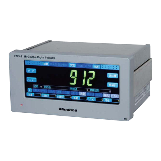
CSD-912B
User Manuals: Minebea CSD-912B Digital Indicator
Manuals and User Guides for Minebea CSD-912B Digital Indicator. We have
1
Minebea CSD-912B Digital Indicator manual available for free PDF download: Instruction Manual
Minebea CSD-912B Instruction Manual (366 pages)
Graphic Digital Indicator
Brand:
Minebea
| Category:
Touch Panel
| Size: 16 MB
Table of Contents
Marks and References Used in this Manual
3
Safety Precautions
3
Location of Installation
3
Power Source
6
Operating Precautions
6
Conformed Standards
7
Function Set When this Is Used in the Tank Weighing System
9
Revision History
10
Table of Contents
11
1 Product Summary
19
Features of CSD-912B
20
Names and Functions of Parts
21
Front Panel
21
Rear Panel
21
2 Wiring
23
Precautions for Wiring
24
Wiring of Strain Gage Based Transducers
25
6-Wires Type Wiring Cable
25
4-Wires Type Wiring Cable
26
Parallel Connection of Load Cells
27
Use of Extension Use Junction Box B-304B
28
Wiring of Power Sources
30
3 Basic Operation
31
Power On/Off
32
How to Read the Display
33
Character Display Pattern
35
Item Selection
36
How to Switch Screens
37
Input of Numerical Values
39
Input of Characters
40
Input of Katakana
40
Input of Alphabetical Characters and Symbols
41
Input of Numeric Characters
41
Other Keys
42
4 Calibration
43
Flow of Calibration
45
Calibration
46
Set the Bridge Power Supply
46
Set the Division (Minimum Scale)
47
Set the Weighing Capacity
48
Span Adjustment
51
Fine Adjustment of Zero Points
54
Fine Adjustment of Span Points
55
Digital Linearization
56
Gravitational Acceleration Compensation
60
Calibration Lock
65
5 Measurement
67
Weighing Mode
68
Simple Comparative Mode
68
Sequential Mode
69
Steps Comparator Mode
71
Preparation of Measurement
72
Weighing Mode Settings
72
Control Mode Settings
73
Brand Settings
75
Measurement in Simple Comparative Mode
87
Measurement in Simple Comparative Batch Mode
87
Measurement in Simple Comparative Discharge Mode
90
Measurement in Sequential Mode
93
Settings before Measurement
93
Measurement in Sequential Batch Mode
107
Measurement in Sequential Mode
107
Measurement in Sequential Discharge Mode
110
Use of Automatic Free Fall Compensation
113
Use of Safety Check Input
115
Settings before Measurement
122
Measurement
124
Brand Settings
127
Measurement
128
Measurement in Nozzle Control Mode
131
Settings before Measurement
131
Mode
131
Measurement
134
Measurement in Recipe Mode
136
Settings before Measurement
136
Measurement
144
Mixture of Measured Objects
146
Measurement in 4 Steps Comparator Mode
150
Settings before Measurement
150
Measurement
156
Operations During Measurement
157
Tare Weight Cancellation
159
Switch between the Standard and the Simple Display
161
Settings Related to Measurement
165
Comparative Target Settings of Zero Band
166
Comparative Target Settings of Full
168
Preset Tare Settings
169
Stability Detection Settings
171
Settings of Tare Weight Cancellation at Power-On
175
Hold Settings
177
Net Weight Sign Inversion Settings
181
Load Value Accumulation Settings
182
6 Graphical Display
189
Graphical Display Description
190
Checking the Transition of Weighing Values (CURSOR OFF)
190
(Cursor On)
192
Graphical Display
194
Settings Related to the Graphical Display
196
Drawing Condition Setting
196
Trigger Level Setting
197
7 Various Settings
200
Settings Related to the Screen Display
200
Display Rate Setting
200
Decimal Point Position Setting
201
OL Display Condition Setting
202
Unit Setting
203
Backlight off Time Setting
203
Settings Related to Compensation
205
Settings Related to the Function Keys
214
Function Setting
214
Setting Function List
216
Setting Initialization
217
Comparative Setting-Related Memory Initialization
217
Operational Setting-Related Memory Initialization
218
8 Data Management
219
Data Types
220
Data Storage Location Setting
222
9 External Equipment
223
Standard RS-485 Interface
224
Standard RS-485 Interface Wiring
224
Communication Setting
226
Modbus Communication
233
2-Wires Method Serial Interface (Serial Interface)
234
Data Format
234
2-Wires Method Serial Interface (Serial Interface) Wiring
235
Output Operation
236
Print Operation Setting
236
External Control I/O
238
External Control I/O Wiring
238
External Control I/O Setting
239
Analog Output
249
BCD Output
256
BCD Output Wiring
257
BCD Output Connector Pin Arrangement
258
I/O Equivalent Circuit
260
Timing Chart
260
BCD Output Setting
262
RS-232C Interface
267
RS-232C Connector Pin Arrangement
267
Communication Setting
269
RS-422/485 Interface
272
RS-422/485 Terminal Block Pin Arrangement
273
Communication Setting
276
10 Maintenance
279
Parts Life
280
Operation Check
281
ROM Version Check
282
Display Check
282
Monitor Mode
284
External Control I/O Check
284
BCD Output Check
285
Maintenance Date Registration
286
Maintenance Number Registration
286
Fuse Replacement
288
11 Troubleshooting
289
Trouble Causes and Corrective Measures
290
Led/Screen Display
291
Weighing Operation
292
Standard RS-485 Interface
292
2-Wires Method Serial Interface (Serial Interface)
293
External Control I/O
293
BCD Output
294
RS-232C Interface
294
Interface
295
Error Display and Buzzer Sound
296
Error Display
296
Sequence Error Display
299
Error Buzzer Sound
300
12 Appendix
301
Menu List
302
Customer Service
310
Warranty
310
Repair
310
Interfaces
312
Modbus Communication Memory Operation Mapping
317
RS-232C/422/485 Communication Data Formats
340
Command Mode Data Formats
340
Advertisement
Advertisement
Related Products
Minebea CSD-581-15
Minebea CSD-709
Minebea CSD-701B
Minebea CSD-815B-73
Minebea CSD-912-73
Minebea CSD-903-EX
Minebea CSD-903-73
Minebea CSD-904-EX
Minebea CSD-892B-73
Minebea CSD-819D
Minebea Categories
Measuring Instruments
Transmitter
Touch Panel
Automobile Parts
Transducer
More Minebea Manuals
Login
Sign In
OR
Sign in with Facebook
Sign in with Google
Upload manual
Upload from disk
Upload from URL