Table of Contents
Advertisement
MINEBEA Co., Ltd.
INSTRUCTION MANUAL
Digital indicator with CC−Link interface
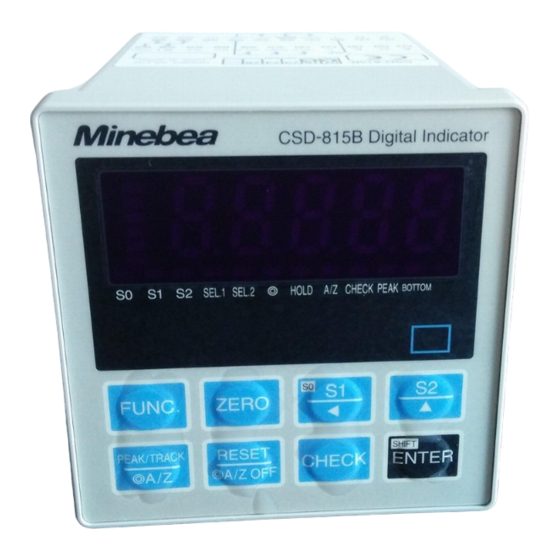
CSD−815B−73
Note : Please read this Instruction Manual carefully before use.
Be sure to follow the items that require attention described in the manual.
Keep the manual at hand so that you can pick it up and read it as soon as
necessity requires.
EN294−1435
Advertisement
Table of Contents

Subscribe to Our Youtube Channel
Related Manuals for Minebea CSD-815B-73


Summary of Contents for Minebea CSD-815B-73
- Page 1 MINEBEA Co., Ltd. INSTRUCTION MANUAL Digital indicator with CC−Link interface CSD−815B−73 Note : Please read this Instruction Manual carefully before use. Be sure to follow the items that require attention described in the manual. Keep the manual at hand so that you can pick it up and read it as soon as necessity requires.
- Page 2 Forwards Thank you very much for your purchasing Minebea’s Digital Indicator with CC−Link interface CSD−815B−73. This manual explains installation procedures and connecting method and also operating method for the Digital Indicator with CC−Link interface CSD−815B−73. When you will use this instrument as the specification with CC−Link interface, make use of it properly after reading through the manual carefully.
-
Page 3: About The View Of This Book
Marks and arrangements used in this manual The following marks are attached to the explanation on the matters that indicate “Don’t do this.”, “Take care.” and “For reference”. Be sure to read these items where these marks are attached. Warning ●... -
Page 4: History Of Revision
History of revision Date Instruction Manual No. Details of revised point First version Nov. 2010 DRW. NO. EN294−1435 CSD−815B main body Ver.1.200 or later CC−Link interface CARD Ver.04 or later... -
Page 5: Table Of Contents
CONTENTS Ⅰ Forwards ..............Ⅱ... -
Page 6: General
1. General This unit is a remote device station of CC−LINK Ver.1.10. This unit can be connected with the mastering station of CC−LINK Ver.1.10. 1−1. Features Main features for CSD−815B−73 are as follows : (1) Because this unit can be controlled by using remote I/O and a remote register of the sequencer, the program volume of the sequencer can be reduced. -
Page 7: Name And Function Of Each Point
2. Name and function of each point 2−1. Rear panel CC−Link I/F point Connector for communication Status LED (1) Connector for communication terminal block Connector type terminal block for CC−LINK interface. Connector type terminal block pin configuration is as follows. Signal cable DA side Signal cable DB side Signal cable ground... - Page 8 (2) Status LED The communication status is expressed with four LED. LED Name Light on Light off Light on/off ・Normal ・In the reset − ・unavailable to communication ・Sending − − ・Receiving − − ・Abnormal setting ・Normal ・When setting changes ・CRC error occurs. ・Trouble...
-
Page 9: Connecting Method
3. Connecting method 3−1. Connector pin configuration for communication Refer to “2−1. Rear panel(1) Connector for communication terminal block”. 3−2. Cable length Relation of baud rate and total extension length as follows. Baud rate Cable length 156 kbps 1 200 m or less 625 kbps 600 m or less 2.5 Mbps... -
Page 10: 3−4. Notes Fo Connection
3−4. Notes of Connection ・When the wiring, be sure to the instrument power supply is OFF. ・Do not supply the AC power until complete the installation. This instrument does not have power switch (ON/OFF). ・Do not fell or make a strong impact on this instrument rear pannel terminal block because it is made of resin. -
Page 11: Setting Of Cc−Link Connecting
4. Setting of CC−Link connecting Please set the following in the function mode when you use CC−LINK interface. Please refer to clause 8−1 of the CSD−815B instruction manual for ”Method of setting the function”. 4−1. Detail of CC−Link setting Setting of the station(Function F−84) The station of CC−LINK is set. -
Page 12: 4−4. 32 Bits Data Expression Method(F−87)
4−4. 32 bits data expression method(F−87) Excute the setting of 32 bits data expression method. The range which can be set is [0] or [1]. Default is set as [0]. Each setting value for 32 bits data expression method is as fallow. F−87 setting value 32 bits data expression method Expression of standard binary... -
Page 13: Pcl Memory Explanation
5. PLC memory explanation 5−1. Address A remote I/O(RX/RY:Bit handling register) and a remote register(RWw/RWr:Word handling register) secures the zone in the master station depends on the occupied station number. As shown in the table below in case of this unit. Occupied station number Remarks Type... -
Page 14: 5−2. Address Map
5−2. Address map In this paragraph, the address of “Remote input”, “Remote output”, and “Remote register” when the station Number of is set. Please note that the address is different when you set the station number except 5−2−1.Data detail (1) Remote register(Master→This instrument) Occupies 4 stations Buffer... - Page 15 Occupies 1 station Buffer Register Station Contents Remarks Address Master→CSD−815B 01E0 RWw0000 01E1 RWw0001 Unused Unused 64 bit 64 bit Special data area Special data area 01E2 RWw0002 01E3 RWw0003 Remote register(Master station→This instrument) Special data area(4 stations ,2 stations ) When the set value is registered by using the set value writing request (request 1), the set value is set in each area.
- Page 16 Commands list(4 stations ,2 stations ) When the command order is executed by using the general command request (request 2), the value set in command No. and the general data area is indicated as follows; Writing the set value and operation request (Writing/Reading out selection=Writing [OFF]) Command No.
- Page 17 (2) Remote register(Instrument→Master) Occupies 4 stations Buffer Register Station Contents Remarks Address Master→Instrument 02E0 RWr0000 OL display OL display ①Net weight value ①Net weight value 02E1 RWr0001 :Set 99999 :Set 99999 −OL display 02E2 RWr0002 ②Gross weight value ②Gross weight value :Set −99999 99999 02E3...
- Page 18 Net weight value(4 stations ,2 stations ) Area for displaying the net weight value :32 bits binary with + or − Data type :−99 999∼99 999 Range of setting value Gross weight value(4 stations ) Area for displaying the gross weight value :32 bits binary with s+ or −...
-
Page 19: 5−2−2.Relay Zone
5−2−2.Relay zone (1) Remote input (Master→This instrument) Occupies 4 stations Device NO. Buffer address Contents Classification ①Setting value writing request (Request 1) RY0000 0160 Communication RY0001 ②General command request (Request 2) RY0002 ③Selection of writing/Reading out. (R/W) RY0003 ④Operation mode changeover request (Request 3) RY0004 RY0005 RY0006... - Page 20 Occupies 2 stations Device NO. Buffer address Contents Classification ①Setting value writing request (Request 1) RY0000 0160 Communication RY0001 ②General command request (Request 2) RY0002 ③Selection of writing/Reading out. (R/W) RY0003 ④Operation mode changeover request (Request 3) RY0004 RY0005 RY0006 RY0007 RY0008 RY0009...
- Page 21 Occupies 1 station Device NO. Buffer address Contents Classification ⑤ZERO RY0000 0160 Communication RY0001 ⑥A/Z ON RY0002 ⑦A/Z OFF RY0003 RY0004 RY0005 RY0006 ⑪Select NET weight value/GROSS weight value RY0007 RY0008 RY0009 RY000A RY000B RY000C RY000D RY000E RY000F RY0010 0161 System data zone RY0011 RY0012...
- Page 22 Selection of writing or reading out(R/W) Select writing or reading out by the command order. Writing the data set in general−purpose data area (RWw000C−RWw000D) by command NO. (RWw000E) is ordered for writing. Reading out the data set in general−purpose data area (RWw000C−RWw000D) by command NO.
- Page 23 (2) Remote output(Master→Instrument) Occupies 4 stations Device NO. Buffer address Contents Classification ①Setting value writing request (Response 1) RX0000 00E0 00E0 Communication Communication RX0001 ②General command response (Response 2) RX0002 RX0003 ③Writing/reading out selection response (R/W response) ④Operation mode changeover response(Response 3) RX0004 RX0005 ⑤CPU normal operation...
- Page 24 Occupies 2 stations Device NO. Buffer address Contents Classification ①Setting value writing request (Response 1) RX0000 00E0 00E0 Communication Communication RX0001 ②General command response (Response 2) RX0002 RX0003 ③Writing/reading out selection response (R/W response) ④Operation mode changeover response(Response 3) RX0004 RX0005 ⑤CPU normal operation RX0006...
- Page 25 Occupies 1 station Device NO. Buffer address Contents Classification ⑦S0 RX0000 00E0 00E0 Control output Control output ⑦S1 RX0001 ⑦S2 RX0002 RX0003 RX0004 RX0005 RX0006 RX0007 ⑧In the holding RX0008 RX0009 RX000A RX000B RX000C RX000D RX000E ⑨Abnormal load value RX000F RX0010 00E1 00E1...
- Page 26 CPU normal operation Notify that CC−LINK interface is operating normally. Reverse the status of ON/OFF in 0.5 seconds. Decimal point position 1, 2, 3 or 4 Notify the decimal point position of the load value by the binary value of three points. This output is updated by turning on the power supply, and initialed data set request flag (RY0079).
-
Page 27: Operation Method
6. Operation method 6−1. Writing the set value (Special data area) The set value is set in the special data area. The instrument recognizes that “Set writing request (request 1) RY0000” was turned on, and it writes the data set in “Special data area (RW0000−RW0009)” into the indicator. It responds to the master station by “Set value writing response RX0000 (response 1)”... -
Page 28: 6−2. Writing/Reading By General Command
6−2. Writing/Reading by general command Data is set in the general data area and command No. is set in the command No. area. The instrument recognize that “General command request RY0002 (Request 2)”, and it execute to write the data set in “General data area (RWr000C∼000D)” by “Selection of writing/reading out (RY0003)”... - Page 29 Reading out request General command request (Request 1) (RY0002) General command response (Response 1) (RX0000) Selection of writing or reading out (RY0003) Command No. (RWw000E) General data (RWw000C) (RWw000D) Command No.(Response) (RWr010E) Selection response of writing or reading out (RX0003)
-
Page 30: 6−3. Shift To Status Where It Is Possible To Communicate
6−3. Shift to status where it is possible to communicate “Remote READY (RX007B)” is turned on along with the power supply turning on after initialization (set initialing) completion is done and it is assumed the status where it is possible to communicate. -
Page 31: Specifications Of Interface
7. Specifications of interface 7−1. CC−Link interface spec Contents Specifications Version of CC−LINK Ver.1.10 Occupied stations No. Selectable from 1,2 or 4 stations. Communication method Polling method Synchronous method Bit synchronization method Baud rate Selectable from 156 kbps, 625 kbps, 2.5 Mbps, 5 Mbps or 10 Mbps Transmission path form RS.485 bus Transmission format... - Page 32 The contents of this manual may subject to change without notice. MINEBEA CO., LTD. HEAD QUARTER : 4106−73 Miyota, Miyota−machi, Kitasakugun, Nagano−ken 389−0293, Japan 0267−32−2200 .0267−31−1350 Measuring Components Business Unit FUJISAWA PLANT 1−1−1, Katase, Fujisawa−shi Kanagawa−ken, 251−8531 Japan ...
Need help?
Do you have a question about the CSD-815B-73 and is the answer not in the manual?
Questions and answers