Advertisement
Quick Links
Advertisement

Related Manuals for Minebea CSD-903-EX


Summary of Contents for Minebea CSD-903-EX
- Page 1 DIGITAL INDICATOR CSD-903-EX Instruction Manual EN294-1492-H...
- Page 3 FOREWORD Thank you very much for your purchasing the digital Indicator CSD-903-EX. This manual is provided to explain installation procedures and check points in operation. We would like you to read through this instruction manual with much care for the best use of our product to avoid malfunctions.
- Page 4 For safe operation Be sure to read this manual before operation. Location of installation Caution Use the Instrument under the following conditions. ● Environmental temperature : -10 ℃ ~ 50 ℃ (Preservation : -20 ℃ ~ 60 ℃) ※The temperature span of JIS B 7611-2 conformity is -10 ℃ ~ 40 ℃. ●...
- Page 5 (2) Installing the Instrument Caution Please secure and set up the spaces between CSD-903 and the devices. Followings are the dimensions of the Instrument and for environmental spaces required: Front Side Rear dimension Panel cut unit: mm The side view when BCD connector is installed. (The I/O connector for external control attached is the same dimension as a BCD connector.) Control I/O Connector BCD out connector (Option)
- Page 6 (3) Applicable environment Warning: The instrument may subject to use in a highly humid area or in full of powder dust. In such a case, use the instrument by inserting the panel mount gasket attached between the control panel (cabinet) and the main body. By inserting the panel mount gasket, the front panel section becomes IP65 (International Protection Code) or equivalent in dust-proof and water-proof construction.
-
Page 7: Power Supply
Power supply Warning Be sure to check that power supply is OFF when installing each cable. If an operator works with power ON, he/she may have an electric shock or the instrument may be destroyed. Warning Before supplying power, check the indication of power voltage/specifications to be identical with supplied power. - Page 8 Conformity standard This instrument has suited the following standard. EN61326:2006 [Electrical equipment for measurement, control, and laboratory use - EMC requirements] [Immunity test requirements for equipment intended for use in industrial locations] EN61010-1:2001 [Safety requirements for electrical equipment for measurement, control and laboratory use - Part 1:General requirement] Annex C (Performance level H) of JIS B 7611-2:2009 [Non-automatic weighing instruments –...
- Page 9 Caution Please observe the following conditions strictly when this instrument suits the JIS standard. If neglected, there is a possibility of not suiting the above-mentioned standard. (3) Setting Functions As for the details of the function of the value of C Function and Function, please refer the paragraph 5-2 and 7-2.
- Page 10 6-9-1. Delete the notes sentence・The tare weight cancellation is not accepted when gross value is below the zero. Due to ECN No.FN12-02088 -Correction- Change of Minebea’s Logo. 2012/12 DRW. NO. EN294-1492-D - Addition- 2-3. Add the applicable connector. 2-4. Add the applicable connector and note.
- Page 11 Data Manual NO. Revision reason(content) Due to ECN No.FN12-02095 -Correction- 7-2., 8-5., 16-3-12.(12) change the explanation of key lock. 7-2., 16-2-2., 16-3-12(12) change the explanation of stream mode. 16-3-14. Correct the explanation of procedure for communications. -Addition- 4-3-8. Add the note. 16-3-14.
- Page 12 RS-232C operating mode external control input. Due to ECN FN16-02057 - Deletion- 2016/05 DRW. NO. EN294-1492-G Delete ‘Minebea Co., LTD. Measuring Components Business Unit’ from the front cover. Due to ECN FN17-02017 2017/08 DRW. NO. EN294-1492-H ・Delete the company name in the contents.
- Page 13 Contents FOREWORD ................................I MARKS AND REFERENCES DESCRIBED IN THIS MANUAL ................I FOR SAFE OPERATION ............................II LOCATION OF INSTALLATION ........................II POWER SUPPLY ............................V INSTRUCTIONS FOR USE ..........................V CONFORMITY STANDARD .......................... VI DIVISIONAL HISTORY ............................VIII NAME AND FUNCTION OF EACH POINT .....................
- Page 14 6-5............................... 37 XCITATION 6-6........................38 ET WEIGHT SIGN INVERSION 6-7..............................38 ERO SET 6-8............................39 ERO TRACKING 6-9............................40 OWER ON ZERO 6-10. T ........................40 ARE WEIGHT CANCELLATION 6-11. C ..........................41 LEAR AT POWER ON 6-12.
- Page 15 VARIOUS FUNCTIONS BY SQ FUNCTION DATA ................... 95 10-1. W ............................95 EIGHING MODE 10-2. C ............................95 ONTROL MODE 10-3. C ....................... 95 OMPARISON SIGNAL OPERATION 10-4. N (ZERO BAND) ................. 95 EAR ZERO COMPARISON OPERATION 10-5. F ........................95 ULL COMPARATIVE OPERATION 10-6.
- Page 16 14-2. D ............................111 ATA FORMAT 14-3. I RS-485 ................111 TEM OF STANDARD COMMUNICATION SETTING 14-4. C ..........................113 ONNECTING METHOD MODBUS COMMUNICATION ......................... 115 15-1. C ..............123 ALIBRATION BY TRANSMISSION THROUGH ODBUS INTERFACE OPTIONS ..............................135 16-1. A ............................
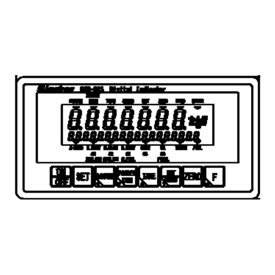
- Page 17 1. Name and function of each point 1-1. Front panel (2) Load display section (3) Condition display section 1 (1) Unit display section (5) Sub display section (4) Condition display section 2 (6) ON/OFF key (13) F key (7) SET key (12) ZERO key (8) ACCUM.
- Page 18 (4) Condition display section 2 Z-BAND It lights when a gross or net load value is under the value set as near zero. It also blinks during setting and selecting the Z-BAND. F.FLOW/S1 It lights when an output signal of full flow is ‘ON’ status in the sequential mode. /PRELIM2 Also when an output signal S1 is ‘ON’...
- Page 19 1-2. Rear panel (5) RS-485 and 2-wires method serial interface terminals (6) External control I/O (4) Calibratin LOCK switch (3) Optional parts mounting section (7) Protected earth terminals (2) Load cell terminals (1) Power supply terminals (1) Power supply terminals It connects with power supply and ground.
- Page 20 1-3. Side (2) Panel mounting metal (1) Model instruction seal (1) Model instructions seal It shows a model number. (2) Panel mounting metal Use when CSD-903 is mounted to the control panel.
- Page 21 2. Connecting wires 2-1. Notes for concerning connecting wires ● When connecting with wires, make sure it was turning off the power supply without fail. ● Do not supply the AC power supply until the installation is completed. There is no switch that switches ON/OFF of power supply in the main body.
- Page 22 2-2. Connection with strain gage applied transducer The instrument can connect with the strain gage applied transducers, such as load cells, pressure sensors, etc. Here, we describe the example of connection with load cells, so that the connection with another type of strain gage applied transducers shall be preceded in the same way. When the tension is applied with the use of tension type or universal (tension/compression) type load cell, and display of (+) direction is required, connect the input (+) of the load cell to the terminal B and the input (-) of the load cell to the terminal D individually.
- Page 23 (2) Case 4-wire type connection cable ・ As using the 4-wire cable, shorten the load cell terminals A - F and C - G with the attached short bar. CSD-903 does not work in normal operation when the terminal F and G is in the open status. ・...
- Page 24 (3) Case connection of the load cells in parallel The hopper scale, the track scale, etc, have the case to connect with several pieces of the load cells in parallel. The parallel connections can be easily executed by using optional SB-310 and SB-320 (Summing type junction box).
- Page 25 (4) Connecting with load cell, Junction box B-304B for extension, and CSD-903 1) When you use CAB-502 (4 core cable) ・ When you use it with 4 wires method, be sure to make a short-circuited between A-F and between C-G of the load cell terminal board. When terminal F and terminal G are used with opening status, CSD-903 cannot make normal operation.
- Page 26 2) When you use CAB-501(6 core cable) The remote sensing function of the instrument does not function enough due to the resistance of the cable at the time of total 100m or more in length of CAB-501 (our standard cable), and there may have the possibility of outside the accuracy guarantee.
- Page 27 2-3. Connection of external control I/O The function can be controlled from the outside with the external control I/O connector on the rear panel. The external control input is executed by shortening each input and COM.1 with a contact point or open collector after wiring the connector.
- Page 28 2-4. Connection of standard RS-485 interface Connect with A, B and S.G. on the output terminals for RS-485 interface and the 2 wire serial interface showing as below figure. Refer to [14-4.Connecting method] as to the connection. With the standard RS-485, either the command mode or the protocol conforming to the Modbus is selectable.
- Page 29 2-5. Connection with 2-wires Serial interface This is the 2-wires method serial interface to connect with a printer, an external display unit, etc. The 2-wires serial interface is connected with +, - and F.G. shown in the below figure. Serial interface corresponding equipment CSD-903Internal equivalent circuit Screw side of terminals...
- Page 30 2-6. Connection with power supply and ground Connect the power supply with the power supply terminal board on the rear panel of the instrument shown as below figure. Grounding should be the D class with the single earth. Warning Connection with the power supply and the earth should be made surely according to the figures, and also within the specified power supply condition.
- Page 31 3. Operation 3-1. Changeover of mode This unit has various modes according to the operating situation. Change the mode by the key operation. Power ON Display check (All light on) Mesurement mode (Display measuring value) Stand-by condition (Light off the measuring value +...
- Page 32 (1) C function mode ( Various functions which relate to calibration by setting C function data become effective. (2) Calibration mode ( By setting the calibration data, the calibration is executed to display the electric signal from the measuring section (load cell) as an accurate load. (3) Check mode ( The ROM version, the each input/output operation, the monitor of load cell output value, the BCD output and the analog output can be confirmed by the check mode.
- Page 33 4. Calibration To be able to display the electrical signal from the measuring section (load cell) as an accurate weight, the operation to match the display of the instrument with the weight loaded on the measuring section is called a calibration. For example to adjust the display of this instrument to 100.00 accurately when the weight of 100 kg is loaded on the measuring section is said.
- Page 34 4-3. Calibration procedures 4-3-1. Flow of calibration Step1 Connect the load cell with this instrument. Connection with load cell Step2 Please energize. Energizing power supply Paragraph 6-5 Step3 Please set the bridge power supply. Set the bridge power supply. Energy for 10 min after Step4 To stabilize this unit and the measuring section (load cell);...
- Page 35 4-3-2. Switch to the calibration mode Change from the standard measurement mode to the Stand-by condition stand-by condition by the key. Pressing the key with the key pressed, it + displays Press the key here. displays. Press the here. displays and it enters into the calibration Calibration mode mode.
- Page 36 4-3-4. Set weighing capacity When key is pressed from display, is displayed. When the weighing capacity has already been changed, the weighing capacity being memorized now is displayed. Memorized weighing Memorized weighing Here, please set the weighing capacity. capacity : The value of changed digit is changed. Changed weighing Changed weighing : Changed digit is selected.
- Page 37 4-3-6. Calibration of zero point When the zero calibration starts, is displayed. Please select the zero calibration method. (1) Method by the measuring data (status of initial load) ⇒ Press the key, and execute the operation of a). Execute the calibration of zero with nothing put on the measuring section. (2) Method by the numeric input of the load cell output voltage.
- Page 38 4-3-7. Calibration of span When the span calibration starts, is displayed. Please select the span calibration method. (1) Method by the measuring ⇒ data Press the key, and execute the operation of a). Execute the span calibration with weight put on the measuring section. (2) Method by the numeric output of the load cell output ⇒Press the key, and execute the operation b).
- Page 39 4-3-8. Quit the calibration is displayed when span calibration is completed. Press the key to quit the calibration mode. The display becomes , and the set data is memorized internally. Press the to set to the stand-by condition. The calibration mode is completed. Stand-by condition Please set the fine adjustment of ZERO and SPAN, digital linearize, ZERO set and Tare weight cancellation after the finish of calibration.
- Page 40 4-4. Fine adjustment of zero and span It is the function to make the fine adjustment of zero and span when there is a difference between the actual measuring value and the weight. 4-4-1. Changeover to zero and span fine adjustment mode Measurement mode Press the key, and move from a usual measurement...
- Page 41 4-4-2. Fine adjustment of zero and span When key pressed from display, is displayed. In executing the zero fine adjustment, proceeds the operation of In case of executing the span adjustment only, press key, and proceed the operation of b) after displaying a) Fine adjustment of Zero Press the key.
- Page 42 c) End of fine adjustment mode Press the key to quit the fine adjustment mode of zero and span. displayed, and the setting data is memorized to the internal memory. Press the key, and move to the stand-by condition. The fine adjustment mode of zero and span is completed.
- Page 43 4-5. Digital linearize. After the calibration, the measurement error of some scale interval levels might be caused between the zero and span (weighing capacity) by the influence of the measuring section etc. The digital linearization function executes the compensation of three points or less except the zero and span, and to reduce the measurement error.
- Page 44 4-5-2. Setting of the digital linearization By pressing the key twice from display, is displayed. As the display Becomes → pressing the key, please select the numbers of points which wants to compensate linearization, and press the : compensation by 1 point : compensation by 2 point : compensation by 3 point Please put the weight of the point which should be the...
- Page 45 Put the weight. Please press the key when the compensation of each point is completed. is displayed. Confirm the stability mark lighting on. Press the key to complete digital linearization mode. is displayed, and the setting data is When P-3 is selected. memorized in the internal memory.
- Page 46 4-6. Calibration only of zero point It is a function for the re-calibration only of the zero point when the amounts of the tare other than the weighing capacity of the measuring section are changed. 4-6-1. Changeover of the calibration mode by zero point Measurement mode Press the key to change from the measurement...
- Page 47 Calibration mode only of zero point Please make the display to by pressing key from the display of Please make to the status where nothing is put on the measuring section here excluding the tare outside weighing capacity. The display of blinks by pressing the key, and start the calibration at zero.
- Page 48 4-7. LOCK of calibration The function change in the calibration and C function can be prohibited by the switch of rear panel. 4-7-1. LOCK by the switch There is calibration LOCK switch inside when the cover at the right of terminals of RS-485 interface and 2-wires type serial interface in the rear panel.
- Page 49 5. C function mode The various functions concerning to the calibration become effective by setting the C function data. 5-1. Setting method of C function data Press the key to change the condition from normal Measurement mode measurement mode to stand-by condition. When the key is pressed with pressing the key,...
- Page 50 5-2. Function of C function data Item Function No. Setting value Contents Display position of CF-01 No decimal point ●0 decimal point. 1234.5 123.45 12.345 1.2345 A/D sampling rate CF-02 20 times/s 200 times/s ●1 Condition of over display CF-03 Bigger than |Weighing capacity +9D| Exceeding to the weighing capacity ±110% Smaller than -20D and larger than weighing...
- Page 51 Item Function No. Setting value Contents Stability detection while the set CF-20 Invalid ●0 mode 2 or set of preset tare Effective Unit display in sub- display section CF-21 Invalid ●0 while the set mode 2 or set of preset tare Effective Method of setting gravity...
- Page 52 Item Function No. Setting value Contents Calibration data of the weight CF-92 ●10000 (Reference use) Calibration data of zero CF-93 ●0.00000 mV/V (Reference use) Calibration data of span CF-94 ●0.30000 mV/V (Reference use) Stability detection time width CF-97 00 ~ 99 Unit : 0.1 s at calibration 00 : OFF of stability detection at calibration...
- Page 53 6. Various functions by C function data 6-1. Setting of decimal point display position The decimal point display position is selected by C function CF-01. The position of the decimal point can be selected from [Nothing], [1234.5], [123.45], [12.345] or [1.2345].
- Page 54 6-6. Net weight sign inversion The net weight sign inversion function is used to invert the sign of the net weight display and net weight data output externally, for example, in simple comparison discharging mode. The net weight sign inversion function is a function for making the net weight display or net weight data output externally positive by inverting the sign of the net weight using C function CF-08.
- Page 55 6-8. Zero tracking The function of zero tracking compensate the gradual zero drift in a constant condition and stabilize the zero point. 6-8-1. Target of zero tracking The zero tracking target is selected by C function CF-12. [Gross value or net value (for load display)] or [Gross value (only at gross value display)] can be selected.
- Page 56 6-9. Power on zero The power on zero function changes the display to zero if the changes of display is within ±10 % of the maximum capacity when the power is turn on, or in the stable condition in the operation of display turning on.
- Page 57 6-11. Clear at power on Setting of the clear at power on is selected by C function CF-18. Clear at power on function is clear [Data of tare weight cancellation], [Data of preset tare weight cancellation] and [Data of zero set and zero tracking] when the power is turn on, or in the operation of display turning on.
- Page 58 6-13-4. Setting of Gravity acceleration value of the using place (When CF-25: 1) The gravity acceleration value of the using place can be set by C function CF-28. Setting range: 9.000 ~ 9.999 Default is set to [9.797]. Please refer to [Gravity acceleration compensation table] in the next page. 6-13-5.
- Page 59 6-14. Automatic range switch Automatic range switch function switches automatically and displays the scale interval by the measuring data of the gross or net value by dividing the range of the measurement to the weighing capacity into 2 or 3. 6-14-1.
- Page 60 Ex.2 In case of net value cancelled 300 g of tare weight set in ex.1 Scale interval 1 g 目量 1 g Scale interval 0.5 g 目量 0.5 g Scale interval 0.1 g 目量 0.1 g 正味量 Net value -300 g 600 g 700 g 300 g Measurement value...
- Page 61 6-17. Memory clear A clear memory is executed by C function CF-99, and the setting contents of C function is returned to the default setting. By pressing the key in the display condition of becomes a blinking. Please press the key to discontinue the clear memory at this point.
- Page 62 7. Function mode Various functions become effective by setting the function data. 7-1. Setting method of the function mode Measurement mode Change from the standard measurement mode to the display by the key. By pressing the key, is displayed. Please select function number which you want to change. : Change the value of changing digit.
- Page 63 7-2. Function of the function data Item Function No. Setting value Contents Setting of digital filter F-01 001 ~ 256 Unit : Moving average time 1 times ●016 Setting of analog filter F-02 2 Hz 4 Hz ●1 6 Hz 8 Hz 10 Hz Display times...
- Page 64 Item Function No. Setting value Contents Selection of sub display F-19 ●0 section A Brand (1 digit) / Accumulation times (6 digits) / Accumulation value (8 digits) B Brand (1 digit) / Accumulation times (6 digits) / Last accumulated data (6 digits) C Brand (1 digit) / Last accumulated data (6 digits) / Accumulation value (8 digits) D Brand (1 digit) / Last accumulated data (6...
- Page 65 Item Function No. Setting value Contents Operation on 4 steps F-22 0000 ~ 1111 0 : OFF comparator 1 : More than ●0000 2 : Less than digit:Comparator S1 digit:Comparator S2 digit:Comparator S3 digit:Comparator S4 Operation of 4 steps F-23 Always OFF ●0 comparator S0...
- Page 66 Item Function No. Setting value Contents RS-232C operating mode F-40 Command mode ●0 Stream mode Synchronizing with finish signal Synchronizing with accumulation signal Synchronizing with print signal Output target of F-41 Display interlock ●0 RS-232C/422/485 (RS-232C : Valid Gross value at F-40 = 1 or 4, Net value RS-422/485 :...
- Page 67 Item Function No. Setting value Contents Operation condition for F-50 000 ~ 121 Accumulation command operation. accumulating function digit: 0 = only in stale, 1 = Always ●000 Automatic accumulating operation digit: 0 = OFF, 1 = Synchronizing with finish, 2 = Automatic accumulation at stable Automatic accumulating condition...
- Page 68 Item Function No. Setting value Contents Emergency stop Manual free fall compensation Net display Forced batch finish Forced discharge finish Accumulation clear for all brands Brand No. 1 Brand No. 2 Brand No. 4 External control input INPUT2 F-61 It is optional as well as F-60 operation setting External control input INPUT3 F-62...
- Page 69 Item Function No. Setting value Contents Eternal control output OUTPUT2 F-71 It is optional as well as F-70 operation setting External control output OUTPUT3 F-72 It is optional as well as F-70 operation setting External control output OUTPUT4 F-73 It is optional as well as F-70 operation setting External control output OUTPUT5 F-74...
- Page 70 8. Various functions by function data 8-1. Digital filter The digital filter function is a steady function by the running average processing of data into which A/D is converted. The running average frequency is selected by setting function F-01. Setting range: 001-256 Units: 1 time of moving average frequency. Default is set to [16 times].
- Page 71 [Example] The data width to which the stabilization filter is executed is selected by the function F-06. The data width of the stabilization filter for each set value [n] is obtained in the display conversion by the following expression. [Data width of stabilization filter] = [Setting value of F-06] x [The scale interval] When the setting by function F-06 is [10], and the scale interval is [D=5], it will be as follows;...
- Page 72 8-5. Key lock function Lock the key function limit a key operation of front panel for avoids wrong operation of keys. 8-5-1. Key lock 1 The function of F-08 sets whether the key operation of [ON/OFF], [SET], [ACCUM./ ] and [PRESET TARE/ ] is [valid] or [invalid].
- Page 73 8-7. Input of the preset tare weight cancellation The preset tare weight cancellation function executes the tare weight cancellation according to the set value by which digital is input. 8-7-1. Operating condition of the preset tare weight cancellation The preset tare weight cancellation can be selected as [Effective], [Invalid], or [Net weight offset operation], using function F-15.
- Page 74 8-8. Print command Execute the setting of print operation of manual and automatic, manual printing operation is used when the print operation is executed by the method either setting the F key to print or using the external control I/O. Automatic print operation is used to print out automatically at every time when load on a weighing section is measured by using a 2-wires method serial interface, BCD output interface or RS-422/485 interface.
- Page 75 (3) Hold of CC-Link interface Whether valid or invalid of holding operation of output data by optional CC-Link interface is selected by the setting of 10 digit of F-18. Default is set to [Invalid]. The holding target when the setting of occupied station for CC-Link interface is selected by 4 stations is [Gross value] and [Net value].
- Page 76 8-11. Accumulation The accumulation function accumulates the load data. Memorize the accumulation times, updated accumulation data and accumulation value 8-11-1. Operating condition for accumulation function Operating condition for accumulation function is selected by function F-50. Setting range: 000-111 digit: Accumulation command operation [0] Only at stable condition, [1] Always digit: Automatic accumulating operation [0] OFF, [1] Synchronized with end signal,...
- Page 77 8-11-4. The clear of accumulation value / the accumulation times Clear the accumulation value and the accumulation times. There are four methods for accumulating as follows. ● Press the key in accumulation display mode. ● Set a key to [Accumulation clear] by setting F-55. ●...
- Page 78 5: Zero clear Return the condition of display before the zero set and zero tracking when the zero set or the zero tracking executed 6: Tare clear Execute the tare weight cancellation 7: Accumulation clear Clear the accumulation value and times 8: Measurement comparison Move to Measurement comparison value setting mode 9: Forced batch finish...
- Page 79 8-14-2. Setting method of the external control output The operation of the external control output is selected by setting function F-70 to F-82. Setting range: 00 ~ 22 0 : OFF No setting 1 : STABLE Output during stable. 2 : DURING TARE Output when the tare weight cancellation is executed.
- Page 80 9. Measurement mode CSD-903 consists of four measurement modes. Please set it with [Clause 9-1]. In addition, please set each measurement comparison value in referring to [Clause 9-2]. Furthermore, there are two control modes about [Simple comparative mode], [Sequential mode], and they divide to [Batch mode], and [Discharge mode].
- Page 81 The outline of each mode is as follows. (1) Simple comparison mode A set value and measured value are compared and whenever the comparative result satisfies the condition, the output turns on. When the gate control etc., are required, PLC etc., are needed. As for the comparison and the judgement condition, refer to each paragraph in [9-3.Simple comparison mode].
- Page 82 9-1. Setting method of the measurement mode Measurement mode Change from the standard measurement mode to the display by the key. Pressing the key, it displays and enters the mode of SQ function. By pressing the key, is displayed. Please select SQ function number which you want to change : The value of changed digit is changed.
- Page 83 9-2. Measurement comparison value setting mode The set value in which each measurement operation in executed in the measurement comparison value setting mode is set. By a selected measurement mode, setting content is different. 9-2-1. Measurement comparison value 1 setting mode The measurement comparison value used in simple comparison mode and sequential mode is set (1) Setting method of measurement comparison value 1 setting mode Change from the standard measurement mode to the...
- Page 84 (2) Function of the data of measurement comparison value 1 Item Set data No. Set value Contents FINAL SET1 000000 ~ 999999 Unit : 1D ●000000 FREE FALL SET2 -999999 ~ 999999 Unit : 1D ●000000 PRELIMINARY 1 SET3 000000 ~ 999999 Unit : 1D ●000000 PRELIMINARY 2...
- Page 85 ● PRELIMINARY 2 Set the value of PRELIMINARY 2. Setting range:000000-999999 Unit:1D Default is set to [000000]. In the sequential mode, when the value of [FINAL(SET1) – PRELIM 2(SET4)] is obtained the F.FLOW output will be ON, and in the simple comparative mode the F.FLOW will be OFF when arrived at the value of [FINAL(SET1) –...
- Page 86 9-2-2. Measurement comparison value 2 setting mode The measurement comparison value used in four steps of comparator modes 1 and 2. (1) Setting method of measurement comparison value 2 setting mode Change from the standard measurement mode to the Measurement mode display by the key.
- Page 87 (2) Function of the data of measurement comparison value 2 Item Set data No. Set value Contents Unit : 1D -999999~999999 ●000000 Unit : 1D -999999~999999 ●000000 Unit : 1D -999999~999999 ●000000 Unit : 1D -999999~999999 ●000000 Near zero SET7 Unit : 1D 000000~999999 ●000000...
- Page 88 9-3. Simple comparison mode The simple comparison mode includes the simple comparison batching mode and the simple comparison discharge mode. To set the simple comparison mode, set in [9-9]. To set the batch mode and the discharge mode, set in [9-9]. 9-3-1.
- Page 89 Measurement Final Final-Free Fall Final-Preliminary1 Final-Preliminary2 Zero band Time Start Full flow Medium flow Dribble flow F-flow comp. stop timer Operate when the start signal is input. M-flow comp. stop timer Judge D-flow comp. stop timer Waiting time for judge Stable Batch finish output on Finish...
- Page 90 9-3-2. Simple comparison discharging mode The simple comparison discharging mode is a mode to output when the judgment condition is satisfied after comparing the decreased value of measured value and set value of each brand at the time of measuring object is discharging. Judgment condition Status display Judgment condition...
- Page 92 9-4. Sequential mode The sequential mode includes the sequential batching mode and the sequential discharge mode. Moreover, Supplementary batching, Initial batching, Nuzzle batching and automatic free flow compensation can be set if necessity requires. 9-4-1. Sequential batching mode The sequential batching mode is a mode to control the measurement sequence depending to the increased value of measuring value when the raw material is batching in.
- Page 94 9-4-2. Sequential batching mode The sequential batching mode is a mode to control the measurement sequence by the decrease value of measured value when the measuring object is batching out. Judgment condition Status display Judgment condition Z-BAND |Gross weight or (Net weight) |≦ ZERO BAND (SET7). F.
- Page 96 9-4-3. Supplementary Batch (discharge) mode Supplementary batch (discharge) is a function to make the Dribble batch ON automatically in fixed time, when the batch (discharge) weight becomes short in the Sequential batch (discharge) mode. In order to execute supplementary batch (discharge), set the items of [Maximum times of supplementary flow], [Time of supplementary batch] and [Waiting time after supplementary batch] after referring to [9-9.
- Page 98 9-4-4. Automatic Free Fall correction This is a function to guess the next Free Fall from a former actual Free Fall, and to set the value of the Free Fall automatically when the measurement is operated continuously. Set data of the next Free Fall uses the moving averaged value calculated from 4 times of actual former Free Fall values.
- Page 99 9-5. 4 steps comparator mode 1 In 4 steps comparator mode, maximum four comparison values and measured value can be compared and output the results. Please set SQ function, SQF-01 to [2] to use this mode. The setting value of each brand number of 4-steps comparator mode can be set by switching F-20: Comparator brand setting target.
- Page 100 9-5-2. Comparative target for comparator S1, S2, S3 and S4 The comparator in this mode, S1, S2, S3 and S4 individually can select the comparative target from [Display interlock], [NET] and [GROSS]. These selections can be made in the Function mode (F-21). Default is set to [Set value or more] for every S1, S2, S3 and S4.
- Page 101 9-5-3. Operation of comparator S0 The comparator S0 in this mode can select one operation among eight operations. This selection can be made in Function mode (F-23). Default is set to [Always off]. Depending on operational selection for comparator, ON/OFF condition for each output may differ. If wrong mode is selected, ON/OFF condition for output becomes inadequate and it may cause an unexpected accident due to malfunction on peripheral instruments, so care should be taken fully.
- Page 102 (2) When S1 selects [Set value or less] and S2 selects [Set value or more] with the Function F−22. S1 output ON at S1 set value ≧ comparison value S2 output ON at S2 set value ≦ comparison value S0 output ON at S1 set value < comparison value < S2 set value comparison value (small) comparison value (large) S1 set value...
- Page 103 9-5-4. Hysteresis on comparator The comparator S1, S2, S3 and S4 in the instrument can set hysteresis for prevention from chattering at output relay. Hysteresis can be used by the combined of data width and time width. Moreover, effective direction for hysteresis can be selected from either [OFF delay] or [ON delay].
- Page 104 (3) When operation of [Set value or more] is selected [ON delay] is selected for hysteresis direction, with Hysteresis time witdh S1 setting value Hysteresis data width Time→ S1 output ON S1 output OFF (4) When operation of [Set value or less] is selected and [OFF delay] is selected for hysteresis direction with S1.
- Page 105 9-6. 4 steps comparator mode 2 In the measurement of the 4 steps comparator node, the comparison results from S0 to S4 is output when the measuring value is in the range of 2 set value after comparing the measuring value with from comparison values or less.
- Page 106 9-6-3. Hysteresis on comparator The comparator S1, S2, S3 and S4 in the instrument can set hysteresis for prevention from chattering at output relay. Hysteresis can be used by the combined of data width and time width. Moreover, effective direction for hysteresis can be selected from either [OFF delay] or [ON delay].
- Page 107 (2) When the operation of effective direction for hysteresis is set as [Off delay] Hysteresis time width S2 setting value Hysteresis data width S1 setting value Hysteresis data width Time→ S0 output ON S0 output OFF S2 output ON S2 output OFF S1 output ON S1 output OFF...
- Page 108 9-7. SQ function mode The setting of SQ function data makes various functions related to the sequence operation effective. 9-8. Setting method of the SQ function mode Measurement mode Change from the standard measurement mode to the display by the key.
- Page 109 9-9. Function of SQ function data Item Function No. Setting value Contents Weighing mode SQF-01 Simple comparison mode Sequential mode ●1 4 steps comparator mode 1 4 steps comparator mode 2 Control mode SQF-02 Batch mode ●0 Discharge mode External input changeover Comparison signal SQF-05 Anytime...
- Page 110 Item Function No. Setting value Contents Judge condition SQF-30 Timer is up ●0 Stable and timer is up Stable or timer is up Waiting time for judge SQF-31 0000 ~ 9999 Unit:0.01s ●0000 0000:Waiting time for judge OFF Maximum time of SQF-35 000to255 Unit:1time...
- Page 111 10. Various functions by SQ function data 10-1. Weighing mode The measurement mode can be selected by the setting of SQ function SQF-01. The measurement mode can be selected from the [Simple comparison mode], [Sequential mode], [4-steps comparator mode 1] or [4-steps comparator mode 2]. Default is set to [Sequential mode].
- Page 112 10-7. Setting for operation at the time batch start 10-7-1. Start above near zero at the time of batch start The operation when input batch start signal with measurement value is exceeded [ZERO BAND] is selected by SQ function SQF-15. When the [Start above near zero at the time of batch start] is set as [Invalid], measurement value is exceeded [Near zero], batching will not be made due to the occurrence of error with the input of batch.
- Page 113 10-11. Flow/Discharge brand setting target The flow/discharge brand setting target is set by SQ function SQF-24. SQF-26: Width for the automatic free fall compensation, SQF-37: Compensation flow time, and SQF-38: Waiting time for judge after compensation flow can be set for each brand number selected as the flow/discharge brand setting target.
- Page 114 10-15. Setting for the operation of compensation flow Set for the operation of compensation flow. 10-15-1. Maximum time of compensation flow Set the maximum time of compensation flow by SQ function SQF-35. Setting range: 000-255, Unit: 1time, 000:OFF Default is set to [000]. 10-15-2.
- Page 115 10-16-2. Batch finish output OFF The condition to make OFF the output of completion of batch can be selected by SQ function SQF-41. The condition to make OFF the output of completion of batch can be selected from [No condition], [OL or unstable] and [Near zero].
- Page 116 10-18. Accumulation clear Accumulation clear is executed by SQ function SQF-98. Clear the accumulation times and the accumulation value. If the key is pressed when displays, becomes blinking. At this time, please press the key to discontinue a clear memory. It becomes a stand-by mode, and a clear memory is not executed.
- Page 117 11. Stored place of setting data In this unit, each data is recorded in RAM and EEPROM as follows: The data in EEPROM can be stored almost permanent due to nonvolatile. Moreover, RAM is backed up with the battery. (The backup time is about ten years in the room temperature.) 11-1.
- Page 118 12. Check mode In the check mode, the following confirmations can be made. ● EzCTS mode ● ROM version ● Confirmation of options ● External control input operation ● External control output operation ● Output voltage of the load cell ●...
- Page 119 12-1. Setting method of Check mode By pressing the key from the normal measurement Measurement mode mode, it enters into the stand-by condition. When the key is pressed with pressing the key, is displayed. + When the key is pressed after pressing the key.
- Page 120 12-2. EzCTS mode When the key is pressed from display, display changes into the blinking display. And it becomes possible to use EzCTS while the display is blinking. EzCTS in communication with the personal computer it can precede reading-out and writing the function data. At this time, the RS-485 interface equipped as a standard becomes effective.
- Page 121 12-4. Confirmation of options When the key is pressed from display, equipped option is blinking displayed. display Combination of optional products Not output Current output Voltage output BCD output CC-LINK interface RS-232C interface RS-422/485 interface Move to the Confirmation of external control input 12-5.
- Page 122 12-6. Confirmation of external control output By pressing key with display, OUTPUT1 of external control output is output after display blinks and [Stable mark] lights. The position when the lighting [▼] mark is displayed moves when key and key is operated at this moment, and the external control output that respond to the position of the mark is turned on.
- Page 123 12-7. Confirmation of load cell output voltage In the confirmation of the load cell output voltage, the weight put on a present load cell is converted into mV/V. For example, when an uncertain load cell is used, please execute the calibration based on the load cell output value with the actual weight for the tare weight and weighing capacity.
- Page 124 12-9. Confirmation of analog output (When the analog output is applied.) By pressing the key from display, is displayed, and the analog output of DC4 mA(DC0 V) is made. At this time, when the under mentioned key is operated, the analog output of DC 12 mA (DC5 V) is output in display, and the analog output of DC DC20 mA (DC10 V) is output in...
- Page 125 13. 2 wire serial interface(S-I/F) 13-1. Interface specification Specifications Contents Baud rate 600 bps Data length 8 bit Parity bit Stop bit 1 bit Start bit 1 bit Sending date Binary code, BCD 13-2. Data format INTERVAL FUN1 FUN2 (1) INTERVAL Space for 15 bit(25 ms) or more (MARK SIGNAL) (2) F1~F3 0FFH code...
- Page 126 ・ Only during the measurement mode, the output of serial data is done. ・ The output of the data of S-I/F stops when the maximum display is set to six digits. Set the maximum display within five digits when you use S-I/F. ・...
- Page 127 14. Standard RS-485 Communication 14-1. Specifications for standard RS-485 communication Specification Content Transmission method Half duplex Synchro system Start-stop synchronization Baud rate Select from 1 200 bps, 2 400 bps, 4 800 bps, 9 600 bps, 19 200 bps and 38 400 bps. Data bit length Select from 7 bit and 8 bit.
- Page 128 (5) Synchronizing with finish signal Data is output when [Forced batch finish] is input by F key or external control input or synchronized with the batch finish signal. RS-485 interface keeps outputting data at the fixed space when the stream mode is selected. Moreover, the control becomes impossible for the host.
- Page 129 14-4. Connecting method 14-4-1. One to one RS-485 host CSD-903 RS-485+ RS-485- B address 00 S.G. S.G.
- Page 130 14-4-2. One to N RS-485 Host CSD-903 RS-485+ RS-485- B Address 00 S.G. S.G. CSD-903 B Address 01 S.G. CSD-903 The terminal resistance is B Address 31 connected in the futhest place away from the host. Make connect the terminal S.G.
- Page 131 15. Modbus communication The Modbus communication is a serial interface used for standard RS-485 communication. The communication with the instrument supported with the Modbus communication can be done without program. - Modbus is a registered trademark of the Modicon Inc. The data communication with CSD-903 does not have to make the program of the communication protocol because it can be operated with the mapped memory operation in the table below.
- Page 132 Input status (bit reading out reference 1) Address Data name Address Data name STABLE DURING TARE NEAR ZERO PRESET TARE FULL CENTER OF ZERO FULL FLOW/S1 GROSS DISPLAY MEDIUM FLOW/S2 NET DISPLAY DRIBBLE FLOW/S3 HOLD OVER/S4 BRAND NO. 0 ACCUMULATION ERROR OK/S0 50~304 UNUSED...
- Page 133 (1) Sequence error number A number is written to input register address 12 when a sequence error occurs. Number Details Action If forcibly stopped by inputting an Check the cause of the emergency stop, emergency stop during weighing reset the error, and restart. If insufficient even after compensation Alter the compensation flow time and flow...
- Page 134 (3) Status error codes Status error codes are written as numbers to input register addresses 52, 56, 60, and 64. Number Details If zero setting was performed outside the valid zero setting range If a number not on the list was selected for C function or function setting A/D conversion error If tare weight cancellation was performed outside the tare weight cancellation operation range...
- Page 135 Address Data name 543~544 BRAND NO. 2 WAITING TIME FOR JUDGE AFTER COMPENSATION FLOW 545~546 BRAND NO. 2 AUTOMATIC FREE FALL COMPENSATION 547~778 UNUSED 779~780 BRAND NO. 3 FINAL/S1 781~782 BRAND NO. 3 FREE FALL/S4 783~784 BRAND NO. 3 PRIOR TO FIXED VALUE 1/S3 785~786 BRAND NO.
- Page 136 Address Data name 1827~53248 UNUSED 53249 BRAND NUMBER 53250~56832 UNUSED 56833 OPERATION MODE 56834 UNUSED 56835~56836 SCALE INTERVAL SETTING 56837~56838 WEIGHING CAPACITY SETTING 56839~56840 WEIGHT MASS SETTING 56841~56842 REGISTER ZERO POINT LOAD CELL OUTPUT VALUE 56843~56844 REGISTER SPAN POINT LOAD CELL OUTPUT VALUE 56845 ACTUAL WEIGHT CALIBRATION STABILITY CONFIRMATION 56846...
- Page 137 Address Data name 57447~57448 F-52 BRAND SELECTION SETTING 57449~57452 UNUSED 57453~57454 F-55 F KEY OPERATION SETTING 57455~57462 UNUSED 57463~57464 F-60 EXTERNAL CONTROL INPUT INPUT 1 OPERATION SETTING 57465~57466 F-61 EXTERNAL CONTROL INPUT INPUT 2 OPERATION SETTING 57467~57468 F-62 EXTERNAL CONTROL INPUT INPUT 3 OPERATION SETTING 57469~57470 F-63 EXTERNAL CONTROL INPUT INPUT 4 OPERATION SETTING 57471~57472...
- Page 138 Address Data name 57941~57492 CF-43 THIRD RANGE SCALE INTERVAL SETTING 57943~57944 CF-44 THIRD RANGE BOUNDARY SETTING 57945~57992 UNUSED 57995~57996 CF-70 ANALOG OUTPUT TARGET 57997~57998 CF-71 DISPLAY VALUE FOR ANALOG OUTPUT OF 4 mA DC (0 V DC) 57999~58000 CF-72 DISPLAY VALUE FOR ANALOG OUTPUT OF 20 mA DC (10 V DC) 58001~58034 UNUSED 58035~58036...
- Page 139 15-1. Calibration by transmission through Modbus interface Please proceed the setting according to the following flow chart in this calibration. 15-1-1. Calibration mode Each item of the flow chart corresponds to each procedure of [4-3. Calibration procedure details]. Please refer to [4-3. Calibration procedure details] for the details. (1) Change to Calibration mode by communication (2) Setting of Scale interval...
- Page 140 (1) Change to calibration mode by communication Shift to the calibration mode by writing [9] at the holding register address 56833. (2) Setting of scale interval The scale interval is written in holding register address 56835 to 56836. Scale interval : Selectable from 1, 2, 5, 10, 20 and 50. Error outside the setting range When the data outside the setting range is written, the following code is set.
- Page 141 (6) Calibration at zero by measurement value The load cell output value is registered in holding register address 56846 as the zero point. [1] is written in holding register address 56846. [1] is automatically rewritten as [0] after writing is normally completed. Setting range : 1 TE-L error [20] (TE-L) is written in input register address 52 when the read load cell output value is less than -2.5...
- Page 142 (8) Confirm the stability of span (Actual weight) Stable/Unstable is read out from holding register address 56845. 0 : Unstable 1 : Stable (9) Calibration at span by measurement value The load cell output value is registered in holding register address 56847 as the span point. [1] is written in holding register address 56847.
- Page 143 (11) Finish calibration The calibration data such as zero point and the span point that is registered temporary are stored in holding register address 56848 and returned to the measurement mode. [1] is written in holding register address 56848. [1] is automatically rewritten as [0] after writing is normally completed. Error outside the setting range When the data outside the setting range is written, the following code is set.
- Page 144 (1) Change to the fine adjustment mode for Zero point and Span point Shift to fine adjustment mode of zero point and span point by writing [10] in holding register address 56833. (2) Zero stability check The weighing values are read out from holding register addresses 56857 to 56858. Stable/Unstable is read out from holding register address 56845 with no load on the measuring section.
- Page 145 (5) Fine adjustment for Span Adjust the display to match the weights loaded on the weighing section. Execute the fine adjustment after writing the data showing in below table in holding register address 56850. Writing holding register address 56850 Fine adjustment at plus side Corse adjustment at plus side Fine adjustment at minus side Corse adjustment at minus side...
- Page 146 15-1-3. Calibration mode of digital linearization Each item of the flow chart corresponds to each procedure of [4-5. Details of procedure for fine adjustment of Zero point and Span point]. Please refer [4-5. Details of procedure for fi ne adjustment of Zero point and Span point] for the details. (1) Change to digital linearization mode (2) Stability check at point No.1 (3) Compensation at point No.1...
- Page 147 (3) Compensation by 1 point The weight amount at point No.1 is set and registered in holding register address 56851 to 56852. Setting range : 1 to Maximum display value LN-L error [24] (LN-L) is written in input register address 52 when input load value is lower than zero point. Condition Error code Contents...
- Page 148 (6) Stability check at point No. 3 Weights are placed for the point to be calibrated on the weighing section and Stable/Unstable is read out from holding register address 56845. 0 : Unstable 1 : Stable (7) Compensation by 3 points After putting the weight of the point which should be compensated on the measuring part, the weight amount at point No.3 is set and registered in holding register address 56855 to 56856.
- Page 149 15-1-4. Calibration mode of zero point only The items in the flowchart correspond to the steps in [4-6 Calibration only of zero point]. For details, refer to [4-6 Calibration only of zero point]. (1) Changing to calibration mode of zero point only (2) Zero stability check (3) Zero calibration using weight (4) Ending calibration mode of zero point only...
- Page 150 Error outside the setting range When the data outside the setting range is written, the following code is set. Condition Error code Contents illegal data 0x03 When data outside [1] is written. (4) Changing to calibration mode at zero point only The calibration data such as zero point and the span point that is registered temporary are stored in holding register address 56848 and returned to the measurement mode.
- Page 151 16. Options 16-1. Analog output 16-1-1. Current output specifications (model: CSD903-P07) Specifications Content Output DC4 mA ~ 20 mA Load characteristic 510 ohm or less Non linearity 0.02 %F.S. Resolution Approx. 1/12000 or more Over range Approx. DC2.4 mA, [-OL] displayed. Approx.
- Page 152 (2) Voltage output Shield Load resistance 5 k-ohm or more + - ・ For the connection with the analog output, be sure to apply the shielded cable and shield should be connected with F.G terminal. ・ To comply the instrument with the CE conformity or applied JIS standard, please use shielded cable and connect the shield with the F.G.
- Page 153 16-1-5. Scaling of analog output The analog output is set as the minimum value ~ the maximum value by 0 to 10 000. This can be made any value by changing CF-71 and CF-72. Analog output アナログ出力 約21.6 mA Approx.21.6 mA 約11 V Approx.11 V 最大値...
- Page 154 Scaling of analog output when set value of CF-03 is set to 0 or 1. Analog output アナログ出力 Approx.21.6 mA 約21.6 mA Approx. 11 V 約11 V the maximum display 最大値 20 mA 10 V -10 % of the maximum display 最大表示の-10 % The minimum display 最小値...
- Page 155 16-1-6. Fine adjustment of analog output After the analog output scaling is executed by setting C function CF-71 and CF-72, the fine adjustment is executed by the trimmer ZERO and the trimmer SPAN. The range of the fine adjustment is approx.±10 % against the full scale. ZERO trimmer SPAN trimmer...
- Page 156 16-2. BCD output 16-2-1. Specifications of BCD output (P/No. : CSD903-P15) Specifications Input/Output Contents BCD data Output 8 digit parallel output. POL. (Polarity) Output ON by minus polarity output, and OFF by plus polarity output. P.C. (Print Output Turning on during the fixed time after the conversion of BCD command) output.
- Page 157 16-2-5. Width of P.C. (Print command) The width of print command is selected by the setting of function F-33. The width of print command is selected from [125 ms], [25 ms] and [5 ms]. Default is set to [25 ms]. The print command becomes unstable in the starting period because of converting the BCD data.
- Page 158 16-2-7. Pin configuration of BCD output connector Pin No. Input/Output BCD code Pin No. Input/Output BCD code Output Output Output Output Output Output Output Output Output Output Output Output Output Output Output Output Output Output Output Output Output Output Output Output Output Output...
- Page 159 16-2-8. Equivalent circuit of input/output Output section Input section =DC30 V =DC20 mA MAX 16-2-9. Timing chart (1) Normal 4 times/s : Approx. 250 ms 4 Times/s:Approx. 250 ms 20 times/s : Approx. 50 ms 20 Times/s:Approx. 50 ms 100 times/s : Approx. 10 ms 100 Times/s:Approx.
- Page 160 (3) When error is occurred DATA POL. P.C. ERROR At the time of ERROR output, output transistor at ERROR signal will become ON (Negative logic electrically). Moreover, for each DATA, POL., all of the output transistor will become OFF at the time of ERROR output (Positive logic electrically).
- Page 161 16-3. RS-232C and RS-422/485 interface 16-3-1. Specifications for RS-232C interface (P/N: CSD903-P74) Specification Contents Communication method Half duplex Synchronous method Start-stop synchronous method Baud rate Selectable from 1 200, 2 400, 4 800, 9 600, 19 200 and 38 400 bps Data bit length Selectable from 7 bit and 8 bit Parity bit...
- Page 162 (1) Command mode Data is sent back from CSD-903 to the host side according to the command/data by sending the command/data to CSD-903 provided by the host (personal computer or sequencer, etc.). Please communicate according to the following procedure. Start Command/Data Host→CSD-903 Data...
- Page 163 16-3-5. Specifications of communication by RS-232C and RS-422/485 The specification of the communication by RS-232C or RS-422/485 is selected by function F-42. Function No. Set value Contents F-42 00000 0 0 0 0 0 ~ 15121 Data bit length 0: 7 bit or 1: 8 bit Parity bit 0: No parity 1: Even parity...
- Page 164 16-3-10. Pin configuration of RS-232C connector Pin No. Signal Name N.C. S.G. N.C. N.C. Suitable plug: DE-9S-NR by JAE or equivalent. ※Not attached. ・ The screws for the fixing base of plug at the connector of RS-232C interface is inch type thread. ・...
- Page 165 16-3-11. Pin configuration of RS-422/485 terminals Difference output (+) Difference output (-) Difference input(+) Difference input(-) Cable end resistance S.G. Signal ground ・ Please connect the internal terminating resistance by shortening between the TRM terminal and RDB terminal which is the furthest from the host. (personal computer, sequencer, etc). ・...
- Page 166 (2) Wiring of 1 to n CSD-903 RS-422 Host RS-485 Host CSD-903 RDB Address 00 RDB Address 00 TRM. TRM. S.G. S.G. S.G. S.G. CSD-903 CSD-903 RDB Address 01 RDB Address 01 TRM. TRM. S.G. S.G. CSD-903 CSD-903 Conect the cable Conect the cable RDBAddress 31 RDB Address 09...
- Page 167 16-3-12. Data format of command mode ・ The address becomes [00] fixation for the RS-232C interface. ・ The load data enters from the right. ・ The sign of [-] for minus and [+] for plus is entered. ・ The load data performs zero suppress. ・...
- Page 168 Terminator Address 00 to 31 When command number is 26 Terminator Command No. Address 00 to 31 Return (CSD-903 → Host) Terminat 6 C1 C2 , C3 C4 , C5 C6 C7 C8 C9 Address 00 to 31 Header 1 Sign Command No.
- Page 169 (2) Reading out the measurement setting data (Host → CSD-903) Operation Command No. Reading out fixed value (SET1) Terminator Reading out free fall (SET2) Address Command No. Reading out prior to fixed value 1 (SET3) 00 to 31 Reading out prior to fixed value 2 (SET4) Reading out over (SET5) Reading out under (SET6) Reading out full (SET8)
- Page 170 (4) Reading out condition 1 (Host → CSD-903) Operation Command No. Reading out condition 1 Terminator Address Command No. 00 to 31 Return (CSD-903 → Host) Terminator Space Address 00 to 31 Condition Command No. a:Accumulate [1] = ON, [0] = OFF b:Preset tare [1] = ON, [0] = OFF c:Tare...
- Page 171 (6) Reading out condition 3 (Host → CSD-903) Operation Command No. Reading out condition 3 Terminator Command No. Address 00 to 31 Return (CSD-903 → host) Terminator Address 00 to 31 Condition Command No. a:N.C. b:DISCHARGE (GATE OPEN) [1] = ON, [0] = OFF c:BATCH FINISH [1] = ON, [0] = OFF d:N.C.
- Page 172 (8) Change of condition (Host → CSD-903) Operation Command No. GROSS DISPLAY NET DISPLAY Terminator ZERO Address Zero clear Command No. 00 to 31 Tare At normal operation Tare clear Return (CSD-903 → Host) Batch start Discharge start Accumulation command Terminator Clear the last accumulated data Address...
- Page 173 (9) Writing the measurement setting data (Host → CSD-903) Terminator Setting value Address Sign 00 to 31 Operation Command No. Command No. Writing fixed value (SET1) Writing free fall (SET2) Writing prior to fixed value 1 (SET3) Writing prior to fixed value 2 (SET4) Writing over (SET5) Writing under (SET6) Writing full (SET8)
- Page 174 The condition of the error transmission becomes as follows. ・ When there is a disagreement in the scale interval value. ・ When you set the value that exceeds the specified value. ・ When you set characters other than the numerical value in the set value. ・...
- Page 175 ・ Please enter the set value by right justify. ・ Please do not put the decimal point. ・ Please set the stored place to the internal RAM when the set value is continuously changed, and the rewriting time of EEPROM might exceed about one million times. ・...
- Page 176 At abnormal operation Return (CSD-903 → host) Terminator Address 00 to 31 (12) Writing set values (host →CSD-903) Terminator Space Address 00 to 31 Command No. At normal operation Return (CSD-903 → host) Terminator Address Setting value 00 to 31 Sign Command No.
- Page 177 A list of Reading out commands Item Function No. Number Set value of Return command Setting the digital filter 1 ~ 256 (Unit : Moving average time 1 times) Setting the analog filter 0 : 2 Hz, 1 : 4 Hz, 2 : 6 Hz, 3 : 8 Hz, 4 : 10 Hz Display time 0 : 4 times/s, 1 : 20times/s Setting of stabilization filter...
- Page 178 Item Function No. Number Set value of Return command Sub display section 0: OFF 1: A Brand (1 digit) / Accumulation times (6 digits) / Accumulation value (8 digits) 2: B Brand (1 digit) / Accumulation times (6 digits) / Last accumulated data (6 digits) 3: C Brand (1 digit) / Last accumulated data (6 digits) / Accumulation value (8 digits) 4: D Brand (1 digit) / Last accumulated data...
- Page 179 Item Function No. Number Contents BCD output operation mode 0 : Stream 1 : SYNC. WITH PRINT 2 : SYNC. WITH ACCUM 3 : SYNC. WITH FINISH BCD output target 0 : Display interlock, 1 : Gross value, 2 : Net value, 3 : Tare weight value,4 : Accumulation total amount 5 : Accumulation frequency BCD output logic...
- Page 180 Item Function No. Number Contents Target of brand changeover 0: Changeover by function 1: Changeover by external control input 2: Changeover by communication Brand number 0 ~ 7 Setting F key operation 0 : OFF, 1 : Print Input, 2: Hold Input, 3 : Batch start, 4 : Emergency stop, 5 : Zero clear, 6 : Tare clear, 7 : Accumulation clear, 8 : Measurement comparison,...
- Page 181 Item Function No. Number Contents External control input INPUT7 It is optional as well as F-60 operation setting External control input INPUT8 It is optional as well as F-60. operation setting External control input INPUT9 It is optional as well as F-60. operation setting External control output 00 : OFF, 01 : Stable,...
- Page 182 Item Function No. Number Contents Display position of decimal 0 : No decimal point, 1 : 1234.5, 2 : 123.45, point. 3 : 12.345, 4 : 1.2345 A/D sampling rate 0 : 20 times/s, 1 : 200 times/s Condition of over display 0 : Bigger than |Weighing capacity +9D| 1 : Exceeding to weighing capacity ±110% 2 : Smaller than -20D and larger than weighing...
- Page 183 Item Function No. Number Contents Analog output target 0 : Display interlock, 1 : Gross value, 2 : Net value Display value at the analog -999999 ~ 999999 output of DC4 mA(DC0 V) Display value at the analog -999999 ~ 999999 output of DC20 mA(DC10 V) Calibration data of the scale 0 : 1 scale interval, 1 : 2 scale interval,...
- Page 184 Item Function No. Number Contents Weighing mode 0 : Simple comparison mode 1 : Sequential mode 2 : 4 steps comparator mode 1 3 : 4 steps comparator mode 2 Control mode 0 : Batch mode, 1 : Discharge mode, 2 : External input changeover Comparison signal operation 0 : ANYTIME, 1 : IN STABLE MODE,...
- Page 185 Item Function No. Number Contents Judge condition 0 : Timer is up 1 : Stable and timer is up 2 : Stable or timer is up Waiting time for judge 0000 ~ 9999 (Unit : 0.01 s) Maximum time of compensation 000 ~ 255 (Unit : 1 time) flow Judge condition after...
- Page 186 (13) Communication error processing This unit returns the error command to the host side when the communication error or the execution error occurs. Terminator Address Error command No. 00 to 31 Error Contents Remarks command No. Non-executable error In the calibration mode, the function mode or the check mode.
- Page 187 16-3-13. Data format synchronizing with data format in Stream mode ・ The load data enters from the right. ・ The sign of [-] for minus and [+] for plus is entered. ・ The load data performs zero suppress. ・ The decimal point adheres to a specified position when the decimal point is set with F-46 and when decimal point is specified with CF-01.
- Page 188 16-3-14. Data format communication calibration ・ The address becomes [00] fixation for the RS-232C interface. ・ The load data enters from the right. ・ The sign of [-] for minus and [+] for plus is entered. ・ The load data performs zero suppress. ・...
- Page 189 ・ CSD-903 displays [ ] (-RS-) during the calibration by communication. ・ When the calibration forced finish is executed, all the calibration registration is not executed, and returned to the condition before calibration. ・ In the case calibration by the registration of the measurement value, please register itself after having confirmed stability by stable confirmation by all means.
- Page 190 (2) Set of the scale interval (Host → CSD-903) Terminator Address Set value 00 to 31 Number Command No. At normal operation Return (CSD-903 → Host) Terminator Address Set value 00 to 31 Number Command No. At abnormal operation Return (CSD-903 → Host) Terminator Address 00 to 31...
- Page 191 (4) Set the mass of the weight. (Host → CSD-903) Terminator Set value Address Number 00 to 31 Command No. At normal operation Return (CSD-903 → Host) Terminator Set value Address Number 00 to 31 Command No. At abnormal operation Return (CSD-903 →...
- Page 192 (6) Zero point registration by the measuring data (Host → CSD-903) Terminator Address 00 to 31 Number Command No. At normal operation Return (CSD-903 → Host Terminator Address Number 00 to 31 Command No. At abnormal operation Return (CSD-903 → Host) Terminator Address 00 to 31...
- Page 193 (7) Numeric input of the load cell output voltage zero point registration. (Host → CSD-903) 1) Input of setting for the forth decimal point digit. Terminator Set value Address 00 to 31 Sign Number Command No. At normal operation Return (CSD-903 → Host) Terminator Address Set value...
- Page 194 At abnormal operation Return (CSD-903 → Host) Terminator Address 00 to 31 Terminator Address 00 to 31 ・ The command that registers mV/V of five digits below the decimal point for ZERO (No.09) and SPAN (No.12) aiming at the performance gain of the calibration is added since ROM Ver. 2.300. When you use the command that newly registers mV/V of ZERO and SPAN, please use the command that registers mV/V of five digits below the decimal point for ZERO (No.9) and SPAN (No.12) ・...
- Page 195 (9) Span registration by the measuring data (Host → CSD-903) Terminator Address Number 00 to 31 Command No. At normal operation Return (CSD-903 → Host) Terminator Address 00 to 31 Number Command No. At abnormal operation Return (CSD-903 → Host) Terminator Address 00 to 31...
- Page 196 4) Input of setting for the fifth decimal point digit Terminator Address Setting value Sign 00 to 31 Number Command No. At normal operation Return (CSD-903 → Host) Terminator Address Setting value Sign 00 to 31 Number Command No. This is the input of the fifth decimal point digit. (ex) Input data = 100001 ⇒1.00001mV/V At abnormal operation Return (CSD-903 →...
- Page 197 (11) Calibration registration (Host → CSD-903) Terminator Address Number 00 to 31 Command No. At normal operation Return (CSD-903 → Host) Terminator Address Number 00 to 31 Command No. At abnormal operation Return (CSD-903 → Host) Terminator Address 00 to 31 (12) Calibration forced finish is executed (Host →...
-
Page 198: Trouble Shooting
17. Trouble shooting When abnormal point(s) is/are found during the operation of the instrument, check by the following procedures. However, when you can't find applicable item nor solve the symptom of trouble even after you have taken some measures, contact with our. 17-1. - Page 199 Inform us about the contents of failure and situation at site in details...
- Page 200 (1) Remove the connecting cable for strain gage applied transducer from the terminal board. (2) Measure the voltage between A-C after short-circuiting A-F and C-G of terminal board. * Set the connecting range to DC-V for the measuring instrument such as tester and so on. The voltage between A and C is stable in the set value of excitation voltage.
- Page 201 (1) Remove the connecting cable for strain gage applied transducer from the terminal. (2) Measure the voltage between A-C after short-circuiting A-F and C-G of terminal board. * Set the connecting range to DC-V for the measuring instrument such as tester and so on. The voltage between A and C is stable in the set value of excitation voltage.
- Page 202 Measurement operation check Is the setting of I/O correct? Set the I/O correct referring to 8-13. Is set value for each BRAND and RECIPE is suitable? Set the measurement comparison value referring to 9-2. Is the intended operation made? Set the operation of measurement referring to 9-3 from 9-9.
- Page 203 To serial interface communication check Standard RS-485 and Modbus are wrong. Inform Minebea about the contents of nform us about the contents of failure and failure and situation in details at site . situation at site in details Correct connecting? Connect surely with the external equipment by referring to the 14-4.
- Page 204 Inform us about the contents of failure and situation at site in details...
- Page 205 Set the external control I/O. External control input is wrong. Inform Minebea about the contents of Inform us about the contents of failure and situation in details. failure and situation at site in details 50 ms or more of input signal is set for the pulse input.
- Page 206 Inform us about the contents of failure and situation at site in details...
- Page 207 Confirm the setting concerning the analog output. Correctly set. Set correctly according to the “16-1. Analog output” Inform Minebea about the contents of Inform us about the contents of failure failure and situation in details. and situation at site in details...
- Page 208 Select the target of BCD output by referring to the “16-2-3. The BCD output does not change. Make the HOLD input opened. Inform Minebea about the contents of Inform us about the contents of failure and situation in details. failure and situation at site in details...
- Page 209 Inform us about the contents of failure and situation at site in details...
- Page 210 Set the flow control to “NONE” from “YES”. The change of RS-422/485 is properly set. Make the change of RS-422/485 correctly. . Inform Minebea about the contents of Inform us about the contents of failure and situation in details. failure and situation at site in details...
- Page 211 There is a possibility not to be able to respond because the host's response is slow. Enlarge the response delay time of the instrument. Inform Minebea about the contents of Inform us about the contents of failure and situation in details.
-
Page 212: Specifications
18. Specifications 18-1. Analog specifications Bridge power supply DC10 V±0.5 V (5 V, 2.5 V) within 180 mA, with remote sensing Applicable transducers Up to 6 pieces of strain gage applied transducers (350 ohm) can be connectable. Input sensitivity 0.2 μV/d or more (d= minimum scale) Input range -3.1 mV/V ~ 3.1 mV/V Zero adjustment range... - Page 213 18-3. Interface External control input Any nine of the following functions can be selected. OFF, [ON/OFF] key operation, [SET] key operation, [ACCUM.] key operation, [PRESET TARE/ ] key operation, [TARE/▲] key operation, [NET/GROSS/▼] key operation, [ZERO] key operation, [F/ ] key operation, Zero clear, Tare clear, Flow start, Discharge start, Clear last accumulated data, Accumulation clear, Error cancellation, Print command, Emergency stop, All brand accumulation clear...
- Page 214 RS-232C Baud rate : Selectable from 1 200, 2 400, 4 800, 9 600, (Sold separately.) 19 200 and 38 400 bps. Data bit length : Selectable from 7 bit and 8 bit Parity bit : Selectable from None, Even and Odd number. Stop bit : Selectable from 1 bit and 2 bit Terminator...
- Page 215 18-4. General specifications Operating Temperature -10 ℃ ~ 50 ℃ temperature ※The temperature span of JIS B 7611-2 conformity is -10 ℃ ~ range 40 ℃ Humidity 85 %RH or less (Non condensing.) Storage temperature range -20 ℃ ~ 60 ℃ Power supply Power-supply AC100 V ~ AC240 V...
- Page 216 19. Error display 19-1. Error Load display Display blinking for about 2 seconds when C function or function is set and no number in the list is selected. Display blinking for about 2 seconds when the calibration is executed, and [Display of the weighing capacity (DISP)] < [Set of mass weight value (LOAD)] is set.
- Page 217 19-2. Error sub display Error code Contents Measures In case of execute ZERO out of Check the range of zero is range of zero appropriate. In case of execute TARE out of Execute the TARE within the range range of tare. of tare.
- Page 218 21. Warranty 21-1. Warranty The instrument is covered by a warranty for a period of one year from the date of delivery. As for repairs and/or after service is required during the period of warranty, contact with us sales office or sales agent from which you have purchased. 21-2.
- Page 219 23. Exchange of fuses 23-1. Exchange procedure of fuse Warning When installation method for the fuse is wrong and/or capacity of installed fuse is inadequate, it causes an unexpected faulty of the instrument. (13) Set OFF the power supply for the instrument. (14) Remove the 6 pieces of screws on the rear panel.
- Page 220 24. Display character pattern The display pattern in seven segments indicator of this instrument is shown in the table below.
- Page 221 25. Setting table for functions Make use of them in case that the customer has changed setting for the function. Setting table for C function Function No. Initial value Customer’s setting Function No. Initial value Customer’s setting CF-01 CF-27 CF-02 CF-28 9.797 CF-03...
- Page 222 Setting table for function Function No. Initial value Customer’s setting Function No. Initial value Customer’s setting F-01 F-48 F-02 F-49 F-04 F-50 F-05 F-51 F-06 F-52 F-07 F-55 F-08 0000 F-60 F-09 0000 F-61 F-10 F-62 F-11 F-63 F-15 F-64 F-16 F-65 F-17...
- Page 223 Setting table of Sub-display panel (F-19) Set value Contents Set value Contents Brand (1 digit) / S1 (6 digits) / S3 (6 digits) Brand (1 digit) / Accumulation times Brand (1 digit) / S1 (6 digits) / S4 (6 digits) / Accumulation value (8 (6 digits) digits) Brand (1 digit) / Accumulation times...
- Page 226 1-1-1, Katase, Fujisawa-shi, Kanagawa-ken, 251-8531 Japan Tel: +81-466-23-2681 Fax: +81-466-22-7191 Sensing Device Business Unit FUJISAWA PLANT 1-1-1, Katase, Fujisawa-shi, Kanagawa-ken, 251-8531 Japan Tel: +81-466-22-7151 Fax: +81-466-22-1701 KARUIZAWA PLANT 4106-73 Miyota, Miyota-machi, Kitasaku gun, Nagano-ken 389-0293 Japan Tel: +81-267-31-1309 Fax: +81-267-31-1353 HOMEPAGE ADDRESS http://www.minebea-mcd.com...
Need help?
Do you have a question about the CSD-903-EX and is the answer not in the manual?
Questions and answers