
Related Manuals for EBS EPX400


Summary of Contents for EBS EPX400
- Page 1 GPRS TRANSMITTER EPX400 Installation and programming manual Issue: Release date: 30.10.2017 Firmware version: 2.3.0 GPRS transmitter configurator version: 1.3.76.3 OSM server version: 1.3.68.2...
- Page 2 DECLARATION OF COMPLIANCE We, EBS Sp. z o.o., declare with full responsibility that the present product meets all requirements provided for in the Directive 1999/5/EC of European Parliament and Council dated 9 March 1999. The copy of “Declaration Compliance” found http://www.ebs.pl/en/certificates/...
-
Page 3: Table Of Contents
TABLE OF CONTENTS INTRODUCTION ..................5 FUNCTIONAL AND TECHNICAL PARAMETERS ......... 6 ASSEMBLY AND WIRING ................ 8 3.1. EPX400 TRANSMITTER ..............8 3.2. PCB VERSION ..................9 3.3. INPUT CONFIGURATION ..............10 QUICK START PROCEDURE ..............11 OPERATION ..................13 PRE-CONFIGURATION VIA ETHERNET PORT ........ - Page 4 11.3. DATA TRANSMISSION ..............68 11.4. RECEIVING OF DTMF DATA ............. 68 11.5. PROGRAMMING ................69 11.6. FIRMWARE UPDATING ..............69 11.7. SIM CARD ERROR ................70 11.8. SYSTEM ERROR ................70 12. CHANGELOG ..................71 EPX400 – Manual Page 4 / 71...
-
Page 5: Introduction
Furthermore there is possibility to transmit not coded messages that are to be comprehensible by reception solutions and also by GPRS Server software. EPX400 transmitter depending on model can be equipped with 2G or 3G modem. Programming of receiver is possible: Locally: - with computer and “GPRS Transmitters Configurator”... -
Page 6: Functional And Technical Parameters
NO (optional) Supported modems model EPX400-50: Cinterion BGS2-W (Quad-Band GSM: 850, 900, 1800, 1900 MHz) model EPX400-60: Cinterion EHS6 (Five Bands UMTS: 800, 850, 900, 1900, 2100 MHz; Quad-Band GSM: 850, 900, 1800, 1900 MHz) Ethernet - 10BaseT/100Base-TX IEEE 802.3 compliant... - Page 7 Cut-off battery voltage level Dimension PCB: 159 x 73 x 35mm Working temperature -10ºC … +55ºC Working humidity 5% … 93% Standards - CE - according with EN 50136-1-1 Grade 3 ATS Class 5 EPX400 – Manual Page 7 / 71...
-
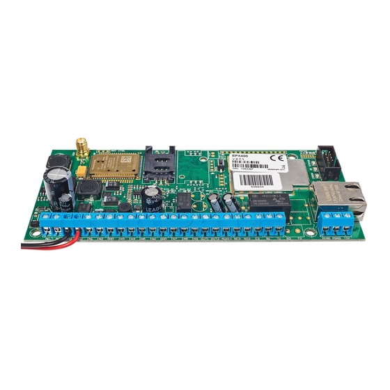
Page 8: Assembly And Wiring
Length of the wires connecting between the transmitter and control panel must not exceed 3 m. 3.1. EPX400 TRANSMITTER Figure 1. Connecting the EPX400 transmitter Connections of wires shall be made with due care to prevent any faults or dead shorts. Places of connections shall be protected against weather conditions. For safety reasons, on AC supply lines must be mounted fuse 400mA/250VAC and double EPX400 –... -
Page 9: Pcb Version
The customer may choose to purchase only PCB version of transmitter. In this case, is required to connect the appropriate power to the AC connectors. ANUFACTURER RESERVES THE RIGHT TO AMEND APPEARANCE OF PRINTED CIRCUIT WITH NO EFFECT ON FUNCTIONALITY OF DEVICE EPX400 – Manual Page 9 / 71... -
Page 10: Input Configuration
2.2kΩ or as double end of line (DEOL-NO or DEOL-NC) with resistor 1.1kΩ. Examples of connecting sensors to the inputs in various configurations are shown in figure 2. Figure 2. Configuration of input lines EPX400 – Manual Page 10 / 71... -
Page 11: Quick Start Procedure
If private network is used, SMS message shall provide the following parameters: UN=<user ID number> PW=<user password>. Exemplary SMS to set the parameters of the GPRS connection is as follows (if we use public network and provide server address as IP): EPX400 – Manual Page 11 / 71... - Page 12 1111█SERVER=89.123.115.8█PORT=6780█APN=general.t-mobile.uk█ UN=█PW= Where: █: space character EPX400 – Manual Page 12 / 71...
-
Page 13: Operation
5. OPERATION EPX400 device is able to transmit data via channel over GSM network, via GPRS, via SMS messages and via Ethernet. Communication mode is configurable – see chapter 8. Programmable parameters for more information. As a result the transmitter may be used only at the territory covered with mobile phone operator network or with wired Ethernet network. -
Page 14: Pre-Configuration Via Ethernet Port
The simplest way to do this is via the built-in web server WWW. To access the server, connect the EPX400 using an Ethernet cable to a PC that has an RJ-45 Ethernet port and a web browser. The device is equipped with Auto MDI-MDIX function – supports straight-through and crossover cable. -
Page 15: Description
6.2. DESCRIPTION “Description” item. Displays information about the type of device and its serial number. 6.3. CONFIGURATION “Configure” item. EPX400 – Manual Page 15 / 71... -
Page 16: Server Parameters
This is usually not required with public APNs. If you have a private APN, you should ask your provider for this parameter. Note: Using a private APN increases the security of the system. EPX400 – Manual Page 16 / 71... -
Page 17: User Password
To unblock the SIM card you will need to enter the PUK code (using any GSM phone) before you can use the card again. Factory PIN number in EPX400 is set to 1111. 6.4. UPDATE FIMWARE The device features a firmware update mechanism. -
Page 18: Contact
To flash new firmware, follow these steps: a) Open the file with the new firmware (click [Browse] to locate the file, which should have the extension “.efi2”, e.g. epx400-2.1.7.efi2). b) Click [Send]. The firmware update process will start. c) After the process is complete, you will see the update status ... - Page 19 EPX400 – Manual Page 19 / 71...
-
Page 20: Configuration Program
(login: ebs, password: ebs). To install program an installation wizard shall be started that performs installation in default place C:\Program Files\EBS\. During installation process shortcuts on screen and Windows menu are created. If device is to be used for the first time it shall be programmed with the above program and after this procedure the SIM card may be inserted into the device. -
Page 21: File -> New
7.3.1. File -> New Opens new set of parameters. Editing of configuration parameters is possible. Select type of device – EPX400. 7.3.2. File -> Open If file contains saved settings, they may be used to program next device. Firstly a folder where file has been saved shall be chosen and then name of file shall be provided. -
Page 22: File -> Language
From this time on program shall enable wires connection with device and reading, and saving of parameters in memory will be possible. In the next tab "MINI-PROG" (the name derived from the programmer) you have to also define the connection parameters. EPX400 – Manual Page 22 / 71... -
Page 23: Remote Connection
Name of connection e.g.: Remote Select name of analyzer e.g.: Primary Enter analyzer address e.g.: www.ebs.pl Enter port on which analyzer operates e.g. 9000 Click on [Add] button to confirm settings. Connections shall be saved (and inserted in table). - Page 24 OSM.Server via GPRS. During programming procedure (with GPRS link- See above) a question will be displayed if user want to use a modem connected to the server. After confirmation procedure will follow as in case of other programming channels. EPX400 – Manual Page 24 / 71...
-
Page 25: File-> Automatic Device Settings Backup
C:\Program Files\ EBS\KonfiguratorLX\configs\EPX400_20000 Folder “EPX400_20000” contains all files associated with programming of the EPX400 with factory number 20000. The name contains date and time of operation and its type (saving/reading). Files have .cmi extension. -
Page 26: Operation -> Device Monitor
Function provides real-time information on device state. See chapter 8.11. Device monitor. 7.3.11. Operation -> System events history Function provides information about last events stored in EPX400 device memory. See chapter 8.12. Events history. 7.3.12. Operation -> Restore default settings If operation “Read”... -
Page 27: Programmable Parameters
Code may consist of up to seven alpha numerical characters. Installer code Allows restricted access to the parameters of device. When installer code is used following groups of parameters are unavailable: Access, Transmission, Restrictions, EPX400 – Manual Page 27 / 71... -
Page 28: Group: Sim Cards
Factory setting of PIN in transmitter is 1111. 8.1.1.3. Option: Embedded HTTP server Selecting this option allows to configure the basic parameters for the EPX400 connection to the server through a Web browser. The method of this configuration is described in chapter "6. Pre-configuration via Ethernet port"... -
Page 29: Server Connection
It determines server port that was selected in server for collection of data from transmitter. Backup Server Address It is address of second (backup) receiver of monitoring system (OSM.Server) or computer where “Communication Server” software has been installed , e.g. EPX400 – Manual Page 29 / 71... -
Page 30: Gprs Parameters
In this case it is required to provide minimum one address of DNS server. Primary Server Port It determines server port that was selected in server for collection of data from transmitter. EPX400 – Manual Page 30 / 71... -
Page 31: Sms Parameters
Any SMS will be sent to this number if transmitter has got problems with GPRS transmission. If this field is left blank or 0 was entered, the transmitter will not be operating in SMS mode. EPX400 – Manual Page 31 / 71... -
Page 32: Communication
You can set channel role as “unused” – so the communication in this way will not be possible. There are four settings possible: Unused Main Backup Emergency EPX400 – Manual Page 32 / 71... - Page 33 Always try to connect to primary server at first Mark this check box means, that the device will try in first order to connect to primary server, without regard on definition of parameters for backup server (especially number of connection attempts). EPX400 – Manual Page 33 / 71...
- Page 34 SMS, but we have greater confidence that the notification arrives as quickly as possible. If this option is disabled, the device stops sending events until it connects to the server. EPX400 – Manual Page 34 / 71...
-
Page 35: Transmission
It activates when closed. EOL and DEOL (single end-of-line resistor and double end-of-line resistor) differ with 1 or 2 resistors allowing distinguishing alarm from sabotage. Electric diagrams for all configuration types were described in chapter 3.3. Input configuration. EPX400 – Manual Page 35 / 71... - Page 36 In case of temporary lock – user can set lock time and number of input state changes after which lock occurs. Lock time is counted from first input state change. More detailed information about input locks is shown on a diagram. EPX400 – Manual Page 36 / 71...
-
Page 37: Partitions
For the active arming input all changes of the state of the input assigned to partition will be monitored and processed in a normal way. EPX400 – Manual Page 37 / 71... - Page 38 8.3.2.5. Entry time Time after which alarm will be generated after delayed input had been armed and partition to which delayed input belongs will not be disarmed. EPX400 – Manual Page 38 / 71...
-
Page 39: Outputs
E.g. if entered number is 1234, the output will activate after incoming call from number 123456789 or 600123456. Note: The phone number must be entered without country code (e.g. without prefix 0048 and +48). EPX400 – Manual Page 39 / 71... -
Page 40: Advanced Outputs Control
“[Off] GSM” and “[On] Input x”. The use the basic configuration of outputs and “Advanced outputs control” at the same time, may cause unexpected behavior of the transmitter. EPX400 – Manual Page 40 / 71... - Page 41 Incoming call from the number defined in option: Inputs/Outputs –> Output 1 / Output 2 / Output 3. The phone number is entered at option: “When incoming call detected from number” (see item 8.3.3.2.). EPX400 – Manual Page 41 / 71...
-
Page 42: Monitoring
(inactive) state. To transmit any event you should only click it (proper square on your right). Click on [Clear] button to remove all marked events. Click on [Invert] button to change markings to contrary. EPX400 – Manual Page 42 / 71... -
Page 43: Sms
3. Device switches to Sleep mode, i.e. the modem goes to off, inputs are not being monitored, outputs are turned off, an external telephone line is attached Sleep mode is indicated by alternating lighting and off LEDs: OK and ERR. EPX400 – Manual Page 43 / 71... -
Page 44: Restrictions
A list of numbers (up to 5 numbers) determines which numbers are allowed to connect with transmitter. Available options: o Deny all: means no available telephone communication. o Allow all: means that telephone communication is possible from any phone. EPX400 – Manual Page 44 / 71... - Page 45 Selection is to be made from scrolled down values by clicking on arrow besides selection area. Allowable options: 5, 10, 15, 30 minutes; 1, 2, 6, 12 hours; 1, 7 days, MAX (meaning no specified time). 8.5.1.4. SMS limits EPX400 – Manual Page 45 / 71...
-
Page 46: Sms Notifications
To edit you shall follow this procedure: o Enter due telephone number into edition field. o Click on [Add] button to transfer number to the below table. o Repeat procedure (up to 5 phone numbers). EPX400 – Manual Page 46 / 71... -
Page 47: Events
If the “Copy the contents from first message” will be marked then selection and text content will be automatically copied from the first message, otherwise you may copy one text and paste to other field manually EPX400 – Manual Page 47 / 71... - Page 48 The format of the test period field is “the total number of days, number of hours:the number of minutes”. No selection in the “Send test every” will disable SMS user tests. EPX400 – Manual Page 48 / 71...
-
Page 49: Status
In reply about status a device shall send one SMS message containing proper text defining actual output , input state and power supply. Note: Counter “Allowed characters” informs about the total number of characters that may be inserted into the table. EPX400 – Manual Page 49 / 71... -
Page 50: Sms Forward
Note: It is a user’s responsibility to provide correct rules which will not create loops of forwarded SMS messages. EPX400 – Manual Page 50 / 71... -
Page 51: Rs232
8.7. RS232 In order to provide additional capabilities for sending information, EPX400 transmitter is equipped with serial port RS-232, 3.3V TTL level. To connect devices equipped with a standard RS-232 or RS-485 the appropriate cables and converters are needed. EPX400 – Manual... -
Page 52: Serial Port Settings
511 bytes. Define criteria that meeting shall mean data transmission to monitoring system transmitter. The following options are available: - After receiving defined ASCII character - After expiry of defined time - After receiving defined amount of characters EPX400 – Manual Page 52 / 71... -
Page 53: Advanced Port Options
This applies to situations where the device has lost GSM connectivity, GPRS transmission is not possible or the Ethernet link is not working. EPX400 – Manual Page 53 / 71... -
Page 54: Watchdog
“Reset submodule” means restarting the communication module of the respective channel: PHY module for the Ethernet channel or GSM/GPRS modem for the GPRS and GSM channels. Enabling the “Reset transmitter” setting is not recommended, but it may be necessary in special situations. EPX400 – Manual Page 54 / 71... -
Page 55: Phone Line
If events registered by the alarm control panel are supposed to be sent by GPRS, this option can be used to separate external line from the alarm control panel. 8.9.1.3. Monitor external phone line voltage EPX400 – Manual Page 55 / 71... -
Page 56: First And Second Phone Number
8.9.1.5. Report intervals between dialled digits This option is being used if in configuration “PSTN line – EPX400 – Alarm Control Panel” there are not other telecommunication devices. If such device will be connected and telephone number will be dialled (and a call will follow) after expiry defined time limit (counted since conclusion of last digit dialling) the transmitter sends a message. - Page 57 (until execution of all determined trials). Select this option to avoid the above mentioned. EPX400 – Manual Page 57 / 71...
-
Page 58: Firmware
Close the window after completed saving. From this time on the device will work under control of new firmware. Note: The above procedure shall be carry out with due care to avoid improper device operation. EPX400 – Manual Page 58 / 71... -
Page 59: Device Monitor
Device time These parameters are also shown in LOG window in text style. All data can be saved to file. Note: Relay output “NC-NO-C” in the Device Monitor window are presented as OUT3. EPX400 – Manual Page 59 / 71... -
Page 60: Events History
„Events history” provides information about last events stored in EPX400 device memory. EPX400 transmitter is able to save at least 5000 events. It is possible to read the history using a GPRS or RS232 connection. In the second case data can be send to PC via GD-PROG cable (the switch in position PROG). - Page 61 EPX400 – Manual Page 61 / 71...
-
Page 62: Device Programming
In second case according to description in chapter 7.3.5.2. Remote connection – GPRS linking, it is required to define remote link on grounds of OSM.Server parameters. As OSM.Server collects (and transmits) information exclusively from EPX400 – Manual Page 62 / 71... -
Page 63: The First Programming Of Device
Save settings in memory of device. Saving course is displayed in special window. c) After saving completion close Configuration Wizard d) The device is ready to transmit data according to new settings. EPX400 – Manual Page 63 / 71... -
Page 64: Receiving Of Sms Message
GPRS channel as "Backup." If the role of the GPRS channel is DIFFERENT than "Unused" (it’s mean turned on), this command sets only the address of the server. EPX400 – Manual Page 64 / 71... - Page 65 EFORMAT - incorrect format of the command; EINVALID - if incomplete (e.g. the lack of port), or entering other characters after “:” than numbers. ETHSERVER= Deleting the set server address. (tzw. empty string) EPX400 – Manual Page 65 / 71...
- Page 66 Samples of commands and device reaction: Parameters setting: 1111 █ APN=general.t-mobile.uk █ SERVER=89.112.43.78 █ PORT=6670 █ SMS=500445566 █ SMSPERIOD=25 Parameters verification: Inquiry: 1111 GETCFG █ Answer: 89.112.43.78:6670,general.t-mobile.uk ██ Inquiry: 1111 GETPARAM=SMS █ Answer:: 500445566 EPX400 – Manual Page 66 / 71...
-
Page 67: Led Diodes Indication
SMS mode. Range indication is interrupted during data transmission, and after sending of data again GSM range is being indicated. LED Diodes Description DTMF ERR OK STATUS Green GSM range = 8 GPRS mode GSM range = 6 GPRS mode EPX400 – Manual Page 67 / 71... -
Page 68: Data Transmission
STATUS LED (blue) and DTMF LED (yellow) indicate actual condition during receiving data from a control panel. Dioda LED Signalling STATUS DTMF ERR OK STATUS DTMF (HandShake) (KissOff) DTMF ERR OK STATUS 6 digits of phone 16 digits ContactID EPX400 – Manual Page 68 / 71... -
Page 69: Programming
LED Diodes Description DTMF ERR OK STATUS Green No program in device (1/sek) Software updating 10 sek Received firmware decoding EPX400 – Manual Page 69 / 71... -
Page 70: Sim Card Error
11.8. SYSTEM ERROR Errors may occure during device operation. An error is indicated by a permanent lighting of red LED. In most cases it means a communication problem with the modem or SIM card. EPX400 – Manual Page 70 / 71... -
Page 71: Changelog
16.03.2017 / v1.5 Updating information about GPRS Transmitter Configurator 27.03.2017 / v1.6 Added information about “Embedded HTTP server” 30.10.2017 / v1.7 Update requirements for the computer in reference to configurator; replacement of OSM.2007 with OSM.Server EPX400 – Manual Page 71 / 71...
Need help?
Do you have a question about the EPX400 and is the answer not in the manual?
Questions and answers