Table of Contents
Advertisement
Quick Links
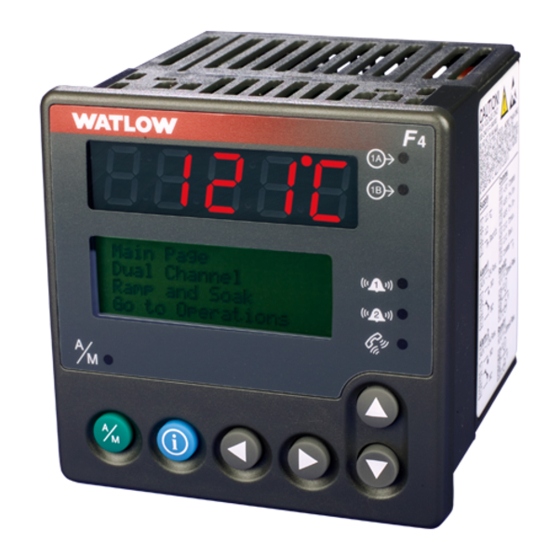
Series F4P
User's Manual
96mm x 96mm Process Controller (1/4 DIN)
with Guided Setup and Programming
1241 Bundy Boulevard, Winona, Minnesota USA
Phone: +1 (507) 454-5300, Fax: +1 (507) 452-4507 http://www.watlow.com
Registered Company
English
Winona, Minnesota USA
0600-0032-0013 Rev D
January 2003
$15.00
Advertisement
Chapters
Table of Contents

Subscribe to Our Youtube Channel
Related Manuals for Watlow F4P Series


Summary of Contents for Watlow F4P Series
- Page 1 Series F4P User’s Manual 96mm x 96mm Process Controller (1/4 DIN) with Guided Setup and Programming 1241 Bundy Boulevard, Winona, Minnesota USA Phone: +1 (507) 454-5300, Fax: +1 (507) 452-4507 http://www.watlow.com Registered Company English Winona, Minnesota USA 0600-0032-0013 Rev D January 2003 $15.00...
- Page 2 Watlow representative (see back cover), or in the U.S., dial +1 (507) 494-5656 between 7 a.m. and 5 p.m., Central Standard Time (CST). Ask for for an Applications Engineer.
-
Page 3: Table Of Contents
..... . Inside Back Cover A downloadable electronic copy of this user manual is available free of charge through Watlow's web site: http://www.watlow.com/literature/prodtechinfo... - Page 4 Notes Table of Contents Watlow Series F4P...
-
Page 5: Chapter 1: Introduction
Chapter One: Introduction Watlow’s Series F4P, 96mm by 96mm (1/4 DIN) Temperature/Process controllers are easy to set up, pro- gram and operate in the most demanding applications. The F4P Temperature/Process controller includes: • four-line, high resolution LCD display; • guided setup software;... -
Page 6: Setup Steps
During all these steps, the Information Key will summon helpful definitions and setup tips. Just position the cur- sor next to the item you want to know more about, then press the key. Press it again to return to your task. 1 .2 Introduction Watlow Series F4P... -
Page 7: Chapter 2: Operating From The Front Panel
Static Message Message 3 save the new ones. >Go to Operations Factory Page Go to Setup Set Lockout Go to Factory Diagnostic Test Calibration Figure 2.1 — Page Navigation. Watlow Series F4P Operating from the Front Panel... -
Page 8: Keys, Displays And Lights
Main Page, and press the Right key again. A message will confirm that the alarm is unlatched. Figure 2.2 — Series F4P Displays and Indicator Lights. 2 .2 Operating from the Front Panel Watlow Series F4P... -
Page 9: Guided Programming
Note: See also differential set point and ratio set should change the set point on the controller. Failure to point. comply with these recommendations may result in dam- age to equipment and property and injury to personnel. Watlow Series F4P Operating from the Front Panel... - Page 10 Main Page.) • Analog input(s) in error condi- • Correct cause of input error. tion. • Input may be in error condition. • Check the alarm output function. 2 .4 Operating from the Front Panel Watlow Series F4P...
- Page 11 • Check sensor isolation. Inputs 2 and 3 are not isolated from each other. Upper [Atod`] • Component failure. • Return to factory for evaluation. Lower !Timeout x (x is 1 to 3) Watlow Series F4P Operating from the Front Panel...
- Page 12 • Checksum error in • Noise on power line. • Add power line filter for input power. Cycle device power. • Component failure. • Return controller to factory for repair. 2 .6 Operating from the Front Panel Watlow Series F4P...
- Page 13 • Place sensor near source. • Output relay open or shorted. • Replace relay. • Sensor shorted. • Replace sensor. • Heater/cooling non-functional. • Repair heating/cooling circuits. • Check circuit breakers, switches, heater elements, compressor. Watlow Series F4P Operating from the Front Panel...
- Page 14 Notes: 2 .8 Operating from the Front Panel Watlow Series F4P...
-
Page 15: Alarm Set Points
The Alarm High Set Point defines the high value that, if exceeded, will trigger an alarm. This value must be higher than the alarm low set point and lower than the high limit of the sensor range. Watlow Series F4P Operations Page... -
Page 16: Autotune Pid
Main Page. It should be stable, ±2%. At this point, the process temperature should also be stable, but it will exhibit droop (stabilized below set point). The droop can be eliminated with integral (re- set). 3 .2 Operations Page Watlow Series F4P... -
Page 17: Multiple Pid Sets
Analog Input 1 sensor, which usually measures results, use proportional control only on the inner loop. the energy source temperature. The output device con- trols a power switching device, which in turn switches Watlow Series F4P Operations Page... - Page 18 10 minutes. Then halve the setting again and wait another 10 minutes until the process value equals the set point. If the process becomes unstable, the integral value is too small. Increase it until the process stabilizes. 3 .4 Operations Page Watlow Series F4P...
-
Page 19: Chapter 4: Setup Page
• Digital Input x (1 to 4); • Control Output x (1A, 1B); • Alarm Output x (1 or 2); • Retransmit Output x (1 or 2); • Communications; and • Custom Main Page and Custom Messages. Watlow Series F4P Setup Page... -
Page 20: Customizing The Main Page
The message is displayed on the Main Page when the digital input is active. This feature could, for instance, display “DOOR OPEN” if an oven door is not closed all the way. 4 . 2 Setup Page Watlow Series F4P... -
Page 21: Chapter 5: Factory Page
Note: For more information about how parameter settings affect the controller’s operation, see the Features Chapter. ç CAUTION: Only authorized and qualified personnel should be allowed to perform preventive and corrective maintenance on this unit. Watlow Series F4P Factor y Page... - Page 22 Set Lockout on the Factory Page. To change a password, you must first enter the old password for Enter Password: confirmation. _ _ _ _ Adjusts Char < Back >Next 5 .2 Factor y Page Watlow Series F4P...
-
Page 23: Diagnostics
Press . once at the Calibrate Input x (1 or 2) prompt (Factory Page). At the 32°F Type J prompt press . once and to store type J thermocouple calibration press > once. 6. Rewire for operation and verify calibration. Watlow Series F4P Factor y Page... - Page 24 RTD calibration. Refer only for other agency requirements or if temperatures to the Ordering Information in the Appendix. aren’t accurate as verified by another calibrated instrument. 5 .4 Factor y Page Watlow Series F4P...
- Page 25 4. Press the Right Key . at the Calibrate Output 1A volt/ammeter reads 1.000V. Press . to store the prompt. At the 20.000mA prompt press . once. Use value. the Up Key > or the Down Key < to adjust the Watlow Series F4P Factor y Page...
- Page 26 The controller should stabilize within one second. Repeat until the volt/ammeter reads 10.000V. Press . to store the value. 8. Rewire for operation and verify calibration. 5 .6 Factor y Page Watlow Series F4P...
-
Page 27: Pages, Menus And Parameters
It may also be helpful for you to make copies of the Pa- rameter Records for each of the pages, as well as the Custom Main Page Record, then record your settings for future reference. Watlow Series F4P Parameters... -
Page 28: Main Page
% Power 1B % Power 1A bar [graph] % Power 1B bar [graph] Tune Status 1 Digital Inputs Note: For more information about how parameter settings affect the controller’s operation, see the Features Chapter. 6 .2 Parameters Watlow Series F4P... - Page 29 Go to Factory Set security settings, cal- ibrate and restore factory settings, perform diag- nostics, test outputs. Note: For more information about how parameter settings affect the controller’s operation, see the Features Chapter. Watlow Series F4P Parameters...
- Page 30 Note: For more information about how param- * None of the B parameters are active if both out- puts are set to cool or heat. eter settings affect the controller’s operation, see the Features Chapter. 6 .4 Parameters Watlow Series F4P...
-
Page 31: Operations Page Parameter Table
0.* Note: For more information about how parameter set- * None of the B parameters are active if both outputs are set to cool or heat. tings affect the controller’s operation, see the Features Chapter. Watlow Series F4P Parameters... - Page 32 Active if Alarm x Type (Setup Point x Low Set Point Page) is set to Process. Set high value at which alarm is triggered. Note: Press the Information Key ˆ for more task-related tips. 6 . 6 Parameters Watlow Series F4P...
- Page 33 Select whether the maxi- Startup or Change (2) mum rate of tempera- ture or process value change will be limited. Note: For more information about how parameter settings affect the controller’s operation, see the Features Chapter. Watlow Series F4P Parameters...
- Page 34 Select the set point value that will be acti- vated by digital input x. The set point name can be changed in the Setup Page. Note: Press the Information Key ˆ for more task-related tips. 6 . 8 Parameters Watlow Series F4P...
- Page 35 Page > Analog Input 2) is set to Switch between the re- Remote 3 (2) Remote. mote and local set points. Note: For more information about how parameter settings affect the controller’s operation, see the Features Chapter. Watlow Series F4P Parameters...
-
Page 36: Operations Page Parameter Record
Dig. SP 1 Dig. SP 2 Dig. SP 3 Dig. SP 4 Digital Set Point x (1 to 4) Digital Differential Set Point x (1 to 4) Digital Ratio Set Point x (1 to 4) 6 .1 0 Parameters Watlow Series F4P... - Page 37 Fixed (1) Select how the outputs will behave if an input error switches the con- troller to manual mode. Note: For more information about how parameter settings affect the controller’s operation, see the Features Chapter. Watlow Series F4P Parameters 6.11...
-
Page 38: Setup Page Parameter Table
Note: Press the Information Key ˆ for more task-relat- *The tenth digit of your model number, F4PX-XXXX-XXXX, ed tips. determines what RTD resistance values the unit uses. Re- fer to the Ordering Information in the Appendix. 6 . 1 2 Parameters Watlow Series F4P... - Page 39 Note: For more information about how parameter set- *Not functional if analog input 3 setup for cascade. tings affect the controller’s operation, see the Features Chapter. **Scale Low value must be less than Scale High value for Normal or Inverse Scaling. Watlow Series F4P Parameters 6.13...
- Page 40 5538 [3] Set the size of the offset. 5539 [4] 5540 [5] 5541 [6] 5542 [7] 5543 [8] 5544 [9] 5545 [10] Note: Press the Information Key ˆ for more task-related tips. 6 . 1 4 Parameters Watlow Series F4P...
- Page 41 AB- _ _ _ _), Analog Input 3 is to the closed valve. selected, Sensor is set to Slidewire and Auto/Manual Calibration is set to Manual. Note: For more information about how parameter settings affect the controller’s operation, see the Features Chapter. Watlow Series F4P Parameters 6.15...
- Page 42 Select the cascade high 1 to 9.999 to Deviation Cascade. Based deviation. (1 to9999) in integer, on decimal setting. tenths, hundredths, thousandths Note: Press the Information Key ˆ for more task-related tips. 6 . 1 6 Parameters Watlow Series F4P...
- Page 43 Activate Message. Set the length of time 3060 [1] that the message will 3061 [2] display. 3062 [3] 3063 [4] Note: For more information about how parameter settings affect the controller’s operation, see the Features Chapter. Watlow Series F4P Parameters 6.17...
- Page 44 * Note: Digital inputs are edge triggered and require a transition from a high to low or low to high state. Note: Press the Information Key ˆ for more task-related tips. 6 . 1 8 Parameters Watlow Series F4P...
- Page 45 Yes on Main Output Active if Alarm Output is en- No (1) Page (0) abled. Select the alarm mes- sage option. Note: For more information about how parameter settings affect the controller’s operation, see the Features Chapter. Watlow Series F4P Parameters 6.19...
- Page 46 Inputs 2 and 3 only available if unit has the Enhanced tips. Control Operation option. The eighth digit of your model number, F4PX-XXX determines the Control Op- eration. Refer to the Ordering Information in the Ap- pendix. 6 . 2 0 Parameters Watlow Series F4P...
- Page 47 (22) % Power 1B bar [graph] (23) Tune Status 1 (24) ***Digital Inputs (25) Active Ch1 PID Set (26) Note: For more information about how parameter settings affect the controller’s operation, see the Features Chapter. Watlow Series F4P Parameters 6.21...
- Page 48 4621-4637 [2] Line 3 4641-4657 [2] 4661-4677 [3] 4681-4697 [3] 4701-4717 [3] 4721-4737 [3] 4741-4757 [4] 4761-4777 [4] 4781-4797 [4] 4801-4817 [4] Note: Press the Information Key ˆ for more task-related tips. 6 . 2 2 Parameters Watlow Series F4P...
-
Page 49: Setup Page Parameter Record
Cascade Cascade Low Range Cascade High Range Cascade Low Deviation Cascade High Deviation Digital Input Digital In 1 Digital In 2 Digital In 3 Digital In 4 Function Name Activate Message Message Display Time Condition Watlow Series F4P Parameters 6.23... - Page 50 Message 2, Line 4 Message 3, Line 1 Message 3, Line 2 Message 3, Line 3 Message 3, Line 4 Message 4, Line 1 Message 4, Line 2 Message 4, Line 3 Message 4, Line 4 6 .2 4 Parameters Watlow Series F4P...
-
Page 51: Custom Main Page Parameter Record
Digital Inputs Active Ch1 PID Set * appears if Input 3 is set to Ratio ** appears if Input 3 is set to Differential Go to Operations Will always appear: Go to Setup Go to Factory Watlow Series F4P Parameters 6.25... - Page 52 Clear Locks Yes (0) 1315 r/w Active: Always. Unlock set point and all pages and menus. Note: For more information about how parameter settings affect the controller’s operation, see the Features Chapter. 6 .2 6 Parameters Watlow Series F4P...
-
Page 53: Factory Page Parameter Table
(0 to 999) Identifies the software revision. Input 1 Univ Single (7) Active: Always. Displays the input 1 type. Note: For more information about how parameter settings affect the controller’s operation, see the Features Chapter. Watlow Series F4P Parameters 6.27... - Page 54 Choose output to test. Output 1B (2) Retransmit 1 (5) Retransmit 2 (6) Alarm 1 (7) Alarm 2 (8) All On (9) Communications (10) Note: Press the Information Key ˆ for more task-related tips. 6 . 2 8 Parameters Watlow Series F4P...
- Page 55 Features Chapter. uses. Refer to the Ordering Information in the Appendix. Ω Options 1-4, 100Ω RTD - 15.00 and 380.00 Ω Options 5-8, 500Ω or 1000Ω RTD - 240.00 and 6080.00 Watlow Series F4P Parameters 6.29...
- Page 56 RTD calibration resistance values the unit tips. uses. Refer to the Ordering Information in the Appendix. Options 1-4, 100Ω RTD - 15.00 and 380.00Ω Options 5-8, 500Ω or 1000Ω RTD - 240.00 and 6080.00Ω 6 . 3 0 Parameters Watlow Series F4P...
- Page 57 Input 3 (2) Restores original factory sion (F4P _ - _ _ AB - _ _ _ _). calibration values. Note: For more information about how parameter settings affect the controller’s operation, see the Features Chapter. Watlow Series F4P Parameters 6.31...
- Page 58 Notes: 6 . 3 2 Parameters Watlow Series F4P...
- Page 59 Ratio Control ......7.17 Slidewire Control ......7.18 Watlow Series F4P Features...
-
Page 60: Chapter 7: Features
(point 1) or higher than the last point (point 10) are zero. Location in software: Setup Page > Analog Input x (1 to 3) Menu > Input Offset x (1 to 10). 7 .2 Features Watlow Series F4P... -
Page 61: Filter Time Constant
Set Point Range (must be between SP Low Limit and SP High Limit) SP Low Limit SP Low Limit Range (between Low Limit of Sensor and SP High Limit) Low Limit of selected Sensor Range Figure 7.3b — Sensor Ranges. Watlow Series F4P Features... -
Page 62: High Scale And Low Scale
The event will continue until the rising edge (low to high state) oc- curs again. Location in software: Setup Page > Digital Input x (1 to 4) Condition. 7 .4 Features Watlow Series F4P... -
Page 63: Control Methods
Location in software: Setup Page > System > Maximum Heat Transfer Power and Maximum Cool Transfer Power. Watlow Series F4P Features... -
Page 64: On-Off Control
With proportional control the output power level equals Figure 7.6b — Proportional Control. (set point minus process value) divided by propband. Location in software: Operations Page > Edit PID > PID Set x (1 to 5). 7 .6 Features Watlow Series F4P... -
Page 65: Pi Control
Time Location in software: Operations Page > Edit PID > PID Figure 7.7c — Cooling Dead Band. Set x (1 to 5). Watlow Series F4P Features... - Page 66 RFI. Location in software: Setup Page > Control Output x (1A or 1B). 50% output 1 ON, 1 OFF 66% output 2 ON, 1 OFF Figure 7.8b — Burst Fire. 7 .8 Features Watlow Series F4P...
-
Page 67: Other Features
[oPLP`] and the lower screen will display “Open Loop.” To clear an open loop error, after correcting the problem that caused it, turn the controller off then back on. Location in software: Setup Page > System. Watlow Series F4P Features... -
Page 68: Alarms
A rate alarm is triggered by a change in temperature or process value that exceeds the selected rate. Location in software: Setup Page > Alarm Output x (1 or 7 .1 0 Features Watlow Series F4P... -
Page 69: Alarm Latching
Alarms can be configured to trigger when the process ex- ceeds the High Alarm Set Point, the Low Alarm Set Point or both. Location in software: Setup Page > Alarm x (1 or 2). (Alarm set points are established in the Operations Page.) Watlow Series F4P Features 7.11... -
Page 70: Advanced Features
Boost set points and boost deviation values are set in the Operations Page > Control Set Points. Time Boost Heat Figure 7.12b — Boost Heat Based on a Fixed Set Point. 7 .1 2 Features Watlow Series F4P... -
Page 71: Duplex
1 hot water temperature transmitter cold water 4 - 20 mA Output 4 - 12 mA 12 - 20 mA -100 to 0% power 0 to100% power Cooling Heating Figure 7.13 — Duplex Application Example. Watlow Series F4P Features 7.13... -
Page 72: Digital Set Points
Main Page. This set point is not adjustable from the Main Page. 25 C 80 C 150 C 250 C Figure 7.14 — Digital Set Points System Example. 7 .1 4 Features Watlow Series F4P... -
Page 73: Features In Enhanced Series F4P Controller
The Series F4P firmware considers the sensor not being used to be off. Out-of-operating-range transitions will cause the Series F4 to switch to the manual mode. Tran- sitions from outside the set point operating range will Watlow Series F4P Features 7.15... - Page 74 Location in software: Setup Page and Operations Page.To set Lube O il Ta nk up and tune a system for cascade control, see the Operations Chapter. Location in software: Setup Page and Operations Page Figure 7.16c -- Cascade Example 7 .1 6 Features Watlow Series F4P...
-
Page 75: Differential Control
Value) can be enabled remotely through designated digi- input 1 output 1 mixed paint input 3 flow flow controlled flow transmitter transmitter of pigment Mix ing Ta nk uncontrolled motorized flow of valve unmixed paint Figure 7.17b — Ratio Control Application Example. Watlow Series F4P Features 7.17... -
Page 76: Slidewire Control
Input 1 - Gas Furnace Sensor Output 1A = Close Valve Actuator Enhanced Output 1B = Open Temperature Sensor Input 3 - Set Point Gas Flow Slidewire Input Figure 7.18b — Slidewire Feedback Application Example. 7 .1 8 Features Watlow Series F4P... - Page 77 Notes: Watlow Series F4P Features 7.19...
- Page 78 Notes: 7 .2 0 Features Watlow Series F4P...
-
Page 79: Installation And Wiring
Wiring Notes ......8.15 Dimensions Figure 8.1 — Front View Dimensions and Gasket Gap Dimension. Watlow Series F4P Installation and Wiring... -
Page 80: Chapter 8: Installation And Wiring
(3.930 in) Go to Factory (3.62 to 3.65 in) 9.5 mm maximum (0.375 in) å ˆ 17.6 mm (0.675 in) minimum 16 mm (0.625 in) minimum Figure 8.2b — Multiple Panel Cutout Dimensions. 8 .2 Installation and Wiring Watlow Series F4P... -
Page 81: Installing The Series F4P
Figure 8.3b — Retention Collar and Mounting Bracket. cutout. If you can, you do not have a proper seal. Do not overtighten. Overtightening could damage the the mounting bracket. Figure 8.3c — Tightening the Screws. Watlow Series F4P Installation and Wiring... -
Page 82: Removing The Series F4P
Hold the bracket steady; do not pull back. Be ready to support the controller as it comes through the front panel. Remove the mounting brackets and retention collar from the back side of the panel. 8 .4 Installation and Wiring Watlow Series F4P... -
Page 83: Communications
Series F4P. Failure to do so could result in such damage, disconnection for servicing. Failure to do so could result and/or injury or death. in damage to equipment and/or property, and/or injury or death to personnel. Watlow Series F4P Installation and Wiring... -
Page 84: Input 1
Available on all units. sensor break protection. Input impedance: 100Ω Outputs can remain full - 62 0 to 50mV Figure 8.6e — Available on all units Impedance: 20MΩ - 62 8 .6 Installation and Wiring Watlow Series F4P... -
Page 85: Inputs X (2 And 3)
RTD (3-wire) 100, 500 or 1000Ω Platinum Figure 8.7c — equipment and product. F4P _ - _ _ AB - _ _ _ _ The last two digits of the model number determine RTD calibration. Input 2 Input 3 Watlow Series F4P Installation and Wiring... - Page 86 Outputs can remain full Slidewire Input (Input 3 only) Figure 8.8d — F4P _ - _ _ _AB - _ _ _ _ Slidewire resistance range: 100 to 1200Ω Input 3 Wiper 8 .8 Installation and Wiring Watlow Series F4P...
- Page 87 Event Ground (27) Digital Input 1 (28) Digital Input 2 (29) Digital Input 3 (30) Digital Input 4 (31) +5VÎ (dc) (32) +5VÎ (dc) Internal Circuitry Watlow Series F4P Installation and Wiring...
-
Page 88: Outputs X (1A And1B )
40 COM. an R.C. suppressor. key pin key pin Watlow carries the R.C. suppressor Quencharc F4 P _ - K _ _ _ - _ _ _ _ F4 P _ - _ K _ _ - _ _ _ _... -
Page 89: Retransmit And Alarm Output
R.C. suppressor. F4P_ -E _ _ _-_ _ _ _ F4P_ -_E_ _ - _ _ _ _ Watlow carries the R.C. suppressor Quencharc brand name, which is a Retransmit and Alarm Output trademark of ITW Paktron. -
Page 90: Communications Wiring
TX Pin 3 TX Pin 2 Black GND Pin 16 Gnd Pin 5 GND Pin 7 Green GND Pin 24 N/U Pin 9 N/U Pin 22 Shield Gnd Pin 5 Gnd Pin 7 8 .1 2 Installation and Wiring Watlow Series F4P... -
Page 91: Chapter 9: Communications
485SD9TB or loss of life, use National Electric Code T-/R- T+/R+ (NEC) standard wiring Watlow p/n 0830-0473-0001 practices to install and Power – operate the Series F4P. 120V (ac) Supply Failure to do so could 6 ft. -
Page 92: Wiring Example
DIN-A-MITE recommendation may DA10-24C0-0000 result in damage to equipment and property Heater and injury to personnel. Series 97 97A1-DDAA-00RR Limit Controller high-temperature light Figure 8.14 — System Wiring Example 8 .1 4 Installation and Wiring Watlow Series F4P... -
Page 93: Wiring Notes
Failure to comply with this recommendation may result in damage to equipment and property and injury to personnel. Figure 8.15 — Wiring Notes. Watlow Series F4P Installation and Wiring 8.15... - Page 94 Notes 8 .1 6 Installation and Wiring Watlow Series F4P...
-
Page 95: Exception Responses
With it you can read all of the con- Modbus protocol, you may want to download the elec- troller’s parameters with a few read commands. tronic F4P Communications Guide from the Watlow web If you already have a software application that uses site: http://www.watlow.com/prodtechinfo. Search on the Modbus, the Modbus Registers Table in this chapter will key words Data Communications. - Page 96 -19999 to Alarm 2 Maximum Rate High -1 1915 Auto/Manual Slidewire Calibration, Analog Input 3 r/w Alarm 2, Status Skip Calibration Automatic Alarm High Manual Alarm Low Autotune PID Alarm Hysteresis, Alarm Output 1 Tune Off 1 to 9999 9 . 2 Communications Watlow Series F4P...
- Page 97 Calibrate Process Output 1A, 20.000mA Clear Alarm 2, Key Press Simulation 0 to 24000mA (in thousandths) write any value 1604 Calibrate Process Output 1A, 4.000mA Clear Error Input 1, Key Press Simulation 0 to 6000mA (in thousandths) Watlow Series F4P Communications...
- Page 98 Derivative 1A, Cascade PID Set 4 Fixed Time 0 to 999 minutes (in hundredths) Cycle Time Type, Control Output 1B 2683 Derivative 1A, Cascade PID Set 5 Variable Burst 0 to 999 minutes (in hundredths) 9 . 4 Communications Watlow Series F4P...
- Page 99 Digital Set Point 4, Control Set Points Set Point Low Limit to Set Point High Limit Panel Lock 1513 Display Test, Test Reset Alarm 1 Perform Display Test Reset Alarm 2 Duplex Output, Control Output 1A Reset Both Alarms Control Outputs Off Watlow Series F4P Communications...
- Page 100 Integral 1B, PID Set 2 1 to 30000 0 to 9999 minutes in hundredths Hysteresis 1B, PID Set 3 Integral 1B, PID Set 3 1 to 30000 0 to 9999 minutes in hundredths 9 . 6 Communications Watlow Series F4P...
- Page 101 None ASCII codes A to Z, 0 to 9, space Mechanical Relay 3020-26 Name (Char 01-07), Digital Input 3 ASCII codes A to Z, 0 to 9, space Process 3030-36 Name (Char 01-07), Digital Input 4 Watlow Series F4P Communications...
- Page 102 Remote 2 rr/w 0 to 30000 Remote 3 2650 Proportional Band 1B, Cascade PID Set 3 2602 Reset 1A, Cascade PID Set 1 0 to 30000 0 to 9999 repeats per minute (in hundredths) 9 . 8 Communications Watlow Series F4P...
- Page 103 1302 Setup Page, Set Lockout Save Full Access Scale High, Analog Input 1 Read Only Depends on sensor and decimal point selection. Password Scale High, Analog Input 2 Hidden Depends on sensor and decimal point selection. Watlow Series F4P Communications...
- Page 104 Units [3 characters] 17 0 to 10V Units, Analog Input 3 18 0 to 50mV Temperature 23 DIN 500Ω RTD Units [3 characters] 24 JIS 500Ω RTD 25 DIN 1kΩ RTD 26 JIS 1kΩ RTD 9 . 10 Communications Watlow Series F4P...
- Page 105 Reset 1A, PID Set 1 Error Latch, Analog Input 1 Derivative 1A, PID Set 1 Units, Analog Input 1 Rate 1A, PID Set 1 Sensor, Analog Input 2 Dead Band 1A, PID Set 1 Sensor Type, Analog Input 2 Watlow Series F4P Communications 9.11...
- Page 106 Condition, Digital Input 3 2604 Rate 1A, Cascade PID Set 1 1066 Function, Digital Input 4 2605 Dead Band 1A, Cascade PID Set 1 1067 Condition, Digital Input 4 2607 Hysteresis 1A, Cascade PID Set 1 9 . 12 Communications Watlow Series F4P...
- Page 107 3061 Message Display Time, Digital Input 2 3062 Message Display Time, Digital Input 3 3063 Message Display Time, Digital Input 4 3070-3072 Units (Char 1-3), Analog Input 1 3073-3075 Units (Char 1-3), Analog Input 2 Watlow Series F4P Communications 9.13...
- Page 108 Notes 9 . 14 Communications Watlow Series F4P...
-
Page 109: Appendix
Software Map ......A.13 About Watlow and Warranty Information ... . -
Page 110: Specifications
Dimensions Inc. • Width x height x depth 3.93 in x 3.93 in x 3.85 in panel mount NOTE: Specifications subject to change without notice. (99 mm x 99 mm x 97 mm) A . 2 Appendix Watlow Series F4P... -
Page 111: Ordering Information
7 = French - 500 Ω & 1000 Ω RTD 8 = Spanish - 500 Ω & 1000 Ω RTD Display and Custom Options RG = Standard Red Upper LED/Green Lower LCD only XX = Custom options: software, setting parameters, overlays Watlow Series F4P Appendix... -
Page 112: Declaration Of Conformity
Erklärt, dass das folgende Produkt: Deutsch Bezeichnung: Serie F4 WATLOW Winona, Inc. Modell-Nummern: F4(S, D oder P)(H or L) – (C, E, F oder K)(A, C, E, F oder K)(A, C, F or K)(A, C, F, K, 0 oder 6) – (0, 1 1241 Bundy Boulevard oder 2) –... -
Page 113: Glossary
(RC) filter. control mode — The type of action that a con- form A — A single-pole, single-throw relay that us- troller uses. For example, on/off, time proportion- es only the normally open (NO) and common con- Watlow Series F4P Appendix... - Page 114 A . 6 Appendix Watlow Series F4P...
- Page 115 See burst fire. acteristic to measure temperature. There are two basic types of RTDs: the wire RTD, which is usual- zero switching — See zero cross. ly made of platinum, and the thermistor, which is Watlow Series F4P Appendix...
-
Page 116: Index
Activate Message 6.17 Auto/Manual Slidewire Calibration Cascade Low Deviation 6.16 active output indicator lights 2.2 6.15 Cascade Low Range 6.16 Address 6.20 automatic and manual operation 2.3 Cascade Outer Loop 6.4 agency approvals A.2 A . 8 Appendix Watlow Series F4P... - Page 117 EIA/TIA 485 and EIA/TIA 232 8.12 – Cycle Time Value 6.18 “i” key 1.2, 2.2 8.13 indicator lights 2.2 enter key 2.3 Information Key 1.2, 2.2 Error Latch 6.15 Input 1 Fail 6.12 errors dead band 3.2, 7.7 Watlow Series F4P Appendix...
- Page 118 Name, Digital Input x (1 to 4) 6.17 output wiring 8.10 – 8.11 lights navigation Output x (1A or 1B), Diagnostic 6.28 active output indicator 2.2 keys 2.2 overshoot 7.7 alarm output indicator 2.2 overview 2.1 communications indicator 2.2 A . 1 0 Appendix Watlow Series F4P...
- Page 119 Channel 1 3.2, 6.4, 7.6 – 7.7 guided 2.3 Retransmit x (1 or 2) 6.28 proportional control 7.6 – 7.7 guidelines 4.1 Reverse outputs 6.17 overview 4.1 proportional integral derivative (PID) Revision 6.27 control 7.7 parameter record 6.23 – 6.24 Watlow Series F4P Appendix A.11...
- Page 120 7.3 transformer isolation 8.5 troubleshooting alarms and errors 2.5 – 2.6 Troubleshooting Chart 2.4 – 2.6 Type, Analog Input x (1 to 3) 6.12 Units 6.13 PID 4.1, 6.11 SI/U.S. 4.1, 6.11 A . 1 2 Appendix Watlow Series F4P...
-
Page 121: Software Map
Boost Delay Time Boost Set Point Digital Set Point x (1 to 4) Digital Differential Set Point x (1 to 4) Digital Ratio Set Point x (1 to 4) Remote/Local Set Points Remote/Local Set Point Watlow Series F4P Appendix A.13... - Page 122 Calibrate Output x (1A or 1B) Boost Power Mode (1B) Calibrate Rexmit x (1 or 2) Boost Set Point Type (1B) Restore In x (1 to 3) Cal Alarm Output x (1 and 2) Name A . 1 4 Appendix Watlow Series F4P...
- Page 123 About Watlow Winona Watlow Winona is a U.S. division of Watlow Electric Mfg. Co., St. Louis, Missouri, a manufacturer of industrial electric heating products since 1922. Watlow products include electric heaters, sensors, controllers and switching devices. The Winona operation has been designing solid-state electronic control devices since 1962, and has earned the reputation as an excellent supplier to original equipment manufacturers.
- Page 124 How to Reach Us Your Authorized Watlow Distributor: United States (headquarters): Asia/Pacific: Watlow Electric Manufacturing Company Watlow Australia Pty., Ltd. 12001 Lackland Road 23 Gladstone Park Drive, St. Louis, Missouri USA 63146 Tullamarine, Victoria 3043 Australia Telephone: +1 (314) 878-4600...
Need help?
Do you have a question about the F4P Series and is the answer not in the manual?
Questions and answers