Table of Contents
Advertisement
Available languages
Available languages
Quick Links
Advertisement
Chapters
Table of Contents

Related Manuals for SICK LBV 331


Summary of Contents for SICK LBV 331
- Page 1 B E T R I E B S A N L E I T U N G LBV 331 - Transistor (NPN/PNP)
-
Page 2: Table Of Contents
Maße........30 LBV 331 • - Transistor (NPN/PNP) -
Page 3: Lbv 331 • - Transistor (Npn/Pnp)
Inhaltsverzeichnis Sicherheitshinweise für Ex-Bereiche Beachten Sie bei Ex-Anwendungen die Ex-spezifischen Sicherheits- hinweise. Diese sind Bestandteil der Betriebsanleitung und liegen jedem Gerät mit Ex-Zulassung bei. Redaktionsstand: 2011-06-17 LBV 331 • - Transistor (NPN/PNP) -
Page 4: Zu Diesem Dokument
Dieses Symbol kennzeichnet besondere Hinweise für Ex-Anwen- dungen. Liste Der vorangestellte Punkt kennzeichnet eine Liste ohne zwingende Reihenfolge. à Handlungsschritt Dieser Pfeil kennzeichnet einen einzelnen Handlungsschritt. Handlungsfolge Vorangestellte Zahlen kennzeichnen aufeinander folgende Hand- lungsschritte. LBV 331 • - Transistor (NPN/PNP) -
Page 5: Zu Ihrer Sicherheit
Bei Arbeiten am und mit dem Gerät ist immer die erforderliche persönliche Schutzausrüstung zu tragen. 2.2 Bestimmungsgemäße Verwendung Der LBV 331 ist ein Sensor zur Grenzstanderfassung. Detaillierte Angaben zum Einsatzbereich finden Sie im Kapitel "Produktbeschreibung". Die Betriebssicherheit des Gerätes ist nur bei bestimmungsgemäßer Verwendung entsprechend den Angaben in der Betriebsanleitung sowie in den evtl. -
Page 6: Sicherheitskennzeichen Am Gerät
EG-Richtlinien. Mit der Anbringung des CE-Zeichens bestätigen wir die erfolgreiche Prüfung. 2.7 Sicherheitshinweise für Ex-Bereiche Beachten Sie bei Ex-Anwendungen die Ex-spezifischen Sicherheits- hinweise. Diese sind Bestandteil der Betriebsanleitung und liegen jedem Gerät mit Ex-Zulassung bei. LBV 331 • - Transistor (NPN/PNP) -
Page 7: Produktbeschreibung
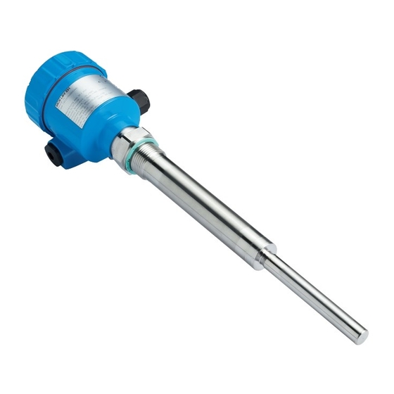
Lieferumfang Grenzstandsensor LBV 331 Dokumentation Dieser Betriebsanleitung Ex-spezifischen "Sicherheitshinweisen" (bei Ex-Ausführun- gen) Ggf. weiteren Bescheinigungen Der LBV 331 besteht aus den Komponenten: Komponenten Gehäusedeckel Gehäuse mit Elektronik Prozessanschluss mit Schwingstab Abb. 1: LBV 331 - mit Kunststoffgehäuse Gehäusedeckel Gehäuse mit Elektronik Prozessanschluss Das Typschild enthält die wichtigsten Daten zur Identifikation und zum... -
Page 8: Arbeitsweise
Schwingstab mit Füllgut bedeckt, ändert sich die Schwingamplitude. Diese Änderung wird vom eingebauten Elektronikeinsatz erfasst und in einen Schaltbefehl umgewandelt. Der LBV 331 ist ein Kompaktgerät, d. h. er kann ohne externe Spannungsversorgung Auswertung betrieben werden. Die integrierte Elektronik wertet das Füllstandsignal aus und stellt ein Schaltsignal zur Verfügung. -
Page 9: Lagerung Und Transport
Trocken und staubfrei lagern Keinen aggressiven Medien aussetzen Vor Sonneneinstrahlung schützen Mechanische Erschütterungen vermeiden Lager- und Transporttemperatur siehe Kapitel "Anhang - Techni- Lager- und Transport- temperatur sche Daten - Umgebungsbedingungen" Relative Luftfeuchte 20 … 85 % LBV 331 • - Transistor (NPN/PNP) -
Page 10: Montieren
Eigenschaften der Medien. Die Angaben dazu finden Sie im Kapitel "Technische Daten" bzw. auf dem Typschild. Grundsätzlich kann der LBV 331 in jeder beliebigen Lage eingebaut Schaltpunkt werden. Das Gerät muss lediglich so montiert werden, dass sich das Schwingelement auf Höhe des gewünschten Schaltpunktes befindet. -
Page 11: Montagehinweise
Rührwerke und Fluidi- der Grenzschalter starken seitlichen Kräften ausgesetzt ist. Wählen sierung Sie aus diesem Grund das Verlängerungsrohr des LBV 331 nicht zu lang, sondern prüfen Sie, ob statt dessen nicht ein kurzer Grenz- schalter seitlich in horizontaler Lage montiert werden kann. - Page 12 4 Montieren Abb. 3: Einströmendes Füllgut Der LBV 331 kann zur stufenlosen Höheneinstellung mit einer Arretierverschraubung Arretierverschraubung montiert werden. Beachten Sie die Druck- angaben der Arretierverschraubung. Das Schwingelement sollte möglichst frei in den Behälter ragen, um Stutzen Ablagerungen zu verhindern. Vermeiden Sie deshalb Stutzen für Flansche und Einschraubstutzen.
- Page 13 4 Montieren Abb. 4: Befüllung und Entleerung mittig Abb. 5: Befüllung mittig, Entleerung seitlich LBV 331 Entleeröffnung Befüllöffnung LBV 331 • - Transistor (NPN/PNP)
- Page 14 Prallschutz gegen Stein- Grobsedimente ist das Schwingelement mit einem geeigneten Prall- schlag blech vor Beschädigungen zu schützen. Dieses Prallblech müssen Sie selbst anfertigen. > 125 mm ") Abb. 6: Prallblech zum Schutz vor Beschädigungen LBV 331 • - Transistor (NPN/PNP)
-
Page 15: An Die Spannungsversorgung Anschließen
Schließen Sie die Betriebsspannung gemäß den nachfolgenden Spannungsversorgung Anschlussbildern an. Beachten Sie dazu die allgemeinen Installa- tionsvorschriften. Verbinden Sie den LBV 331 grundsätzlich mit der Behältererde (PA) bzw. bei Kunststoffbehältern mit dem nächstgele- genen Erdpotenzial. Seitlich am Gerätegehäuse befindet sich dazu eine Erdungsklemme zwischen den Kabelverschraubungen. -
Page 16: Anschlussplan Einkammergehäuse
Dichtring muss das Kabel komplett umschließen 10 Eventuell neuen Abgleich durchführen 11 Gehäusedeckel verschrauben Der elektrische Anschluss ist somit fertig gestellt. 5.3 Anschlussplan Einkammergehäuse Die nachfolgenden Abbildungen gelten sowohl für die Nicht-Ex-, als auch für die EEx-d-Ausführung. LBV 331 • - Transistor (NPN/PNP) - Page 17 Abb. 8: Werkstoffvarianten Einkammergehäuse Kunststoff (nicht bei EEx d) Aluminium Edelstahl, elektropoliert Filterelement für Luftdruckausgleich Wir empfehlen den LBV 331 so anzuschließen, dass der Schalt- Anschlussplan stromkreis bei Grenzstandmeldung, Leitungsbruch oder Störung geöffnet ist (sicherer Zustand). Zum Ansteuern von Relais, Schützen, Magnetventilen, Leuchtmel- dern, Hupen sowie von SPS-Eingängen.
-
Page 18: Anschlussplan - Ausführung Ip 66/Ip 68, 1 Bar
5.4 Anschlussplan - Ausführung IP 66/IP 68, 1 bar Aderbelegung An- schlusskabel Abb. 12: Aderbelegung Anschlusskabel. Die Nummern der Adern entsprechen den Anschlussklemmen des Gerätes. Braun (+) Spannungsversorgung Weiß Gelb Blau (-) Spannungsversorgung Abschirmung LBV 331 • - Transistor (NPN/PNP) -
Page 19: In Betrieb Nehmen
DIL-Schalter zur Betriebsartenumschaltung - min./max. (2) Kontrollleuchte (5) Hinweis: Stellen Sie generell vor der Inbetriebnahme des LBV 331 mit dem Betriebsartenschalter (2) die Betriebsart ein. Wenn Sie den Betriebs- artenschalter (2) nachträglich umschalten, ändert sich der Schaltaus- gang. Das heißt, nachgeschaltete Geräte werden evtl. betätigt. -
Page 20: Funktionstabelle
(> 0,3 g/cm³ bzw. 0.011 lbs/in³). Bei besonders leichten Schüttgütern drehen Sie das Potentiometer auf Linksanschlag (0,02 … 0,1 g/cm³ bzw. 0.0007 … 0.0036 lbs/in³). Damit wird der LBV 331 empfindlicher und kann leichte Schüttgüter sicherer detektieren. Bei Geräten zur Feststoffdetektion in Wasser gelten diese Ein- stellungen nicht. - Page 21 6 In Betrieb nehmen Füllstand Schaltzustand Kontrollleuchte Betriebsart min. offen Trockenlaufschutz Ausfall der Span- beliebig offen nungsversorgung (Betriebsart min./ max.) Störung beliebig offen blinkt rot LBV 331 • - Transistor (NPN/PNP)
-
Page 22: Instandhalten Und Störungen Beseitigen
Es liegt in der Verantwortung des Anlagenbetreibers, geeignete Verhalten bei Störungen Maßnahmen zur Beseitigung aufgetretener Störungen zu ergreifen. Der LBV 331 bietet Ihnen ein Höchstmaß an Funktionssicherheit. Störungsursachen Dennoch können während des Betriebes Störungen auftreten. Diese können z. B. folgende Ursachen haben:... -
Page 23: Elektronikeinsatz Tauschen
Gehen Sie wie folgt vor: Spannungsversorgung abschalten Gehäusedeckel abschrauben Öffnungshebel der Klemmen mit einem Schraubendreher an- heben Anschlussleitungen aus den Klemmen herausziehen Die beiden Halteschrauben mit einem Schraubendreher (Torx Größe T10 oder Schlitz 4) lösen LBV 331 • - Transistor (NPN/PNP) -
Page 24: Das Gerät Reparieren
14 Kabelverschraubung auf Dichtigkeit überprüfen. Der Dichtring muss das Kabel komplett umschließen. 15 Gehäusedeckel verschrauben Der Elektroniktausch ist somit abgeschlossen. 7.4 Das Gerät reparieren Sollte eine Reparatur erforderlich sein, wenden Sie sich bitte an die zuständige Sick-Vertretung. LBV 331 • - Transistor (NPN/PNP) -
Page 25: Ausbauen
Mensch und Umwelt und ermöglicht eine Wiederverwendung von wertvollen Rohstoffen. Werkstoffe: siehe Kapitel "Technische Daten" Sollten Sie keine Möglichkeit haben, das Altgerät fachgerecht zu entsorgen, so sprechen Sie mit uns über Rücknahme und Entsorgung. LBV 331 • - Transistor (NPN/PNP) -
Page 26: Anhang
140 Nm, max. 400 N (103 lbf ft, max. 90 lbf) Ausgangsgröße Ausgang Potenzialfreier Transistorausgang, dauerkurz- schlussfest Laststrom < 400 mA Schaltspannung < 55 V DC Sperrstrom < 100 µA Betriebsarten (umschaltbar) min./max. Schaltverzögerung Bei Bedeckung 0,5 s LBV 331 • - Transistor (NPN/PNP) - Page 27 Flanschtemperatur) mit Temperaturzwi- schenstück (optional) 80°C (176°F) 40°C (104°F) 0°C (32°F) -50°C 50°C 100°C 150°C 200°C 250°C (-58°F) (122°F) (212°F) (302°F) (392°F) (482°F) -40°C (-40°F) Abb. 26: Umgebungstemperatur - Prozesstemperatur Prozesstemperatur Umgebungstemperatur Temperaturbereich mit Temperaturzwischenstück LBV 331 • - Transistor (NPN/PNP)
- Page 28 Farbe - Standard PUR Blau Farbe - Ex-Ausführung Blau Bedienelemente Betriebsartenschalter max. 20 mm (0.8 in) bei Füllgutdichte < 0,05 g/cm³ (0.002 lbs/in³). Je nach Ausführung M12 x 1, nach ISO 4400, Harting, 7/8" FF. LBV 331 • - Transistor (NPN/PNP)
- Page 29 Geräte mit Zulassungen können je nach Ausführung abweichende technische Daten haben. Bei diesen Geräten sind deshalb die zugehörigen Zulassungsdokumente zu beachten. Diese sind im Gerätelieferumfang enthalten. Voraussetzung für die Einhaltung der Schutzart ist das passende Kabel. LBV 331 • - Transistor (NPN/PNP)
-
Page 30: Maße
~ 116 mm (4.57") ø 80 mm (2.72") ø 79 mm ø 86 mm (3.39") (3.15") (3.11") M20x1,5/ M20x1,5/ M20x1,5 M20x1,5/ ½ NPT ½ NPT ½ NPT Abb. 27: Gehäuseausführungen Kunststoffgehäuse Aluminiumgehäuse Edelstahlgehäuse, elektropoliert LBV 331 • - Transistor (NPN/PNP) - Page 31 9 Anhang ø 29mm (1 ") ø16mm ( ") Abb. 28: LBV 331 - Gewindeausführung G1 A (DIN ISO 228/1) Sensorlänge, siehe Kapitel "Technische Daten" LBV 331 • - Transistor (NPN/PNP)
- Page 32 9 Anhang G1½A ø 29mm (1 ") ø16mm ( ") Abb. 29: LBV 331 - Gewindeausführung G1½ A (DIN ISO 228/1) Sensorlänge, siehe Kapitel "Technische Daten" LBV 331 • - Transistor (NPN/PNP)
- Page 33 9 Anhang ø 34 mm (1.34") Abb. 30: Temperaturzwischenstück LBV 331 • - Transistor (NPN/PNP)
- Page 34 9 Anhang LBV 331 • - Transistor (NPN/PNP)
- Page 35 9 Anhang LBV 331 • - Transistor (NPN/PNP)
- Page 36 LBV 331 39165-DE-110617...
- Page 37 O P E R A T I N G I N S T R U C T I O N S LBV 331 - transi stor (NPN/PNP)
- Page 38 Technical data ......26 Dimensions ....... 30 LBV 331 • - transistor (NPN/PNP)
- Page 39 Safety instructions for Ex areas Please note the Ex-specific safety information for installation and operation in Ex areas. These safety instructions are part of the operating instructions manual and come with the Ex-approved instruments. Editing status: 2011-06-17 LBV 331 • - transistor (NPN/PNP)
-
Page 40: About This Document
This symbol indicates special instructions for Ex applications. List The dot set in front indicates a list with no implied sequence. à Action This arrow indicates a single action. Sequence Numbers set in front indicate successive steps in a procedure. LBV 331 • - transistor (NPN/PNP) -
Page 41: For Your Safety
During work on and with the device the required personal protective equipment must always be worn. 2.2 Appropriate use The LBV 331 is a sensor for level detection. You can find detailed information on the application range in chapter "Product description". -
Page 42: Safety Label On The Instrument
2.7 Safety instructions for Ex areas Please note the Ex-specific safety information for installation and operation in Ex areas. These safety instructions are part of the operating instructions manual and come with the Ex-approved instruments. LBV 331 • - transistor (NPN/PNP) -
Page 43: Product Description
The LBV 331 consists of the components: Constituent parts Housing cover Housing with electronics Process fitting with vibrating rod Fig. 1: LBV 331 - with plastic housing Housing cover Housing with electronics Process fitting The type label contains the most important data for identification and... -
Page 44: Principle Of Operation
Solid detection in water If LBV 331 was ordered for solid detection in water, the vibrating rod is calibrated to the density of water. If covered by water (density: 1 g/cm³/ 0.036 lbs/in) LBV 331 signals "uncovered". Only if the vibrating element is also covered with solids (e.g. -
Page 45: Storage And Transport
Not exposed to corrosive media Protected against solar radiation Avoiding mechanical shock and vibration Storage and transport temperature see chapter "Supplement - Storage and transport temperature Technical data - Ambient conditions" Relative humidity 20 … 85 % LBV 331 • - transistor (NPN/PNP) -
Page 46: Mounting
You can find the specifications in chapter "Technical data" or on the type label. In general, LBV 331 can be installed in any position. The instrument Switching point only has to be mounted in such a way that the vibrating element is at the height of the desired switching point. -
Page 47: Mounting Instructions
For this reason, do not tion use an overly long extension tube for LBV 331, but check if you can mount a short level switch on the side of the vessel in horizontal position. - Page 48 4 Mounting Fig. 3: Inflowing medium LBV 331 can be mounted with a lock fitting for height adjustment. Take Lock fitting note of the pressure information of the lock fitting. The vibrating element should protrude into the vessel to avoid buildup.
- Page 49 4 Mounting Fig. 4: Filling and emptying centred Fig. 5: Filling in the centre, emptying laterally LBV 331 Discharge opening Filling opening LBV 331 • - transistor (NPN/PNP)
- Page 50 This baffle must be manufactured by you. > 125 mm ") Fig. 6: Baffle for protection against mechanical damage LBV 331 • - transistor (NPN/PNP)
-
Page 51: Connecting To Power Supply
Voltage supply Take note of the general installation regulations. As a rule, connect LBV 331 to vessel ground (PA), or in case of plastic vessels, to the next ground potential. On the side of the instrument housing there is a ground terminal between the cable entries. -
Page 52: Wiring Plan, Single Chamber Housing
10 If necessary, carry out a fresh adjustment 11 Screw the housing cover on The electrical connection is finished. 5.3 Wiring plan, single chamber housing The following illustrations apply to the non-Ex as well as to the EEx-d version. LBV 331 • - transistor (NPN/PNP) - Page 53 Plastic (not with EEx d) Aluminium Stainless steel, electro-polished Filter element for air pressure compensation We recommend connecting LBV 331 in such a way that the switching Wiring plan circuit is open when there is a level signal, line break or failure (safe condition).
-
Page 54: Wiring Plan - Version Ip 66/Ip 68, 1 Bar
Wire assignment con- nection cable Fig. 12: Wire assignment connection cable. The numbers of the wires correspond to the terminals of the instrument. brown (+) voltage supply White Yellow blue (-) voltage supply Shielding LBV 331 • - transistor (NPN/PNP) -
Page 55: Set Up
Note: As a rule, always set the mode with mode switch (2) before starting the setup of LBV 331. The switching output will change if you set the mode switch (2) afterwards. This could possibly trigger other connected instruments or devices. -
Page 56: Function Chart
(> 0.3 g/cm³/0.011 lbs/in³). In very light solids you have to turn the potentiometer to the complete left position (0.02 … 0.1 g/cm³ or 0.0007 … 0.0036 lbs/in³). By doing this, LBV 331 will be more sensitive and light solids can be detected more reliably. - Page 57 6 Set up Level Switching status Control lamp Failure of the sup- open ply voltage (min./max. mode) Failure open flashes red LBV 331 • - transistor (NPN/PNP)
-
Page 58: Maintenance And Fault Rectification
The operator of the system is responsible for taking suitable measures Reaction when malfunc- to rectify faults. tions occur LBV 331 offers maximum reliability. Nevertheless, faults can occur Causes of faults during operation. These may be caused by the following, e.g.: Sensor... -
Page 59: Exchanging The Electronics Module
Unscrew the housing cover Lift the opening levers of the terminals with a screwdriver Pull the connection cables out of the terminals Loosen the two screws with a screw driver (Torx size T10 or slot 4) LBV 331 • - transistor (NPN/PNP) -
Page 60: Instrument Repair
14 Check cable gland on tightness. The seal ring must completely encircle the cable. 15 Screw the housing cover on The electronics exchange is now finished. 7.4 Instrument repair If it is necessary to repair the instrument, please contact the responsible Sick agency. LBV 331 • - transistor (NPN/PNP) -
Page 61: Dismounting
Correct disposal avoids negative effects on humans and the environ- ment and ensures recycling of useful raw materials. Materials: see chapter "Technical data" If you have no way to dispose of the old instrument properly, please contact us concerning return and disposal. LBV 331 • - transistor (NPN/PNP) -
Page 62: Supplement
Output variable Output Floating transistor output, permanently shortcircuit- proof Load current < 400 mA Turn-on voltage < 55 V DC Blocking current < 100 µA Modes (adjustable) min./max. Switching delay When immersed 0.5 s LBV 331 • - transistor (NPN/PNP) - Page 63 40˚C (104˚F) 0˚C (32˚F) -50˚C 50˚C 100˚C 150˚C 200˚C 250˚C (-58˚F) (122˚F) (212˚F) (302˚F) (392˚F) (482˚F) -40˚C (-40˚F) Fig. 26: Ambient temperature - Process temperature Process temperature Ambient temperature Temperature range with temperature adapter LBV 331 • - transistor (NPN/PNP)
- Page 64 Min. detection or dry run protection Max. Max. detection or overflow protection max. 20 mm (0.8 in) with product density < 0.05 g/cm³ (0.002 lbs/in³). Depending on the version M12 x 1, according to ISO 4400, Harting, 7/8" FF. LBV 331 • - transistor (NPN/PNP)
- Page 65 Depending on the version, instruments with approvals can have different technical data. For these instruments, please note the corresponding approval documents. They are included in the scope of delivery. A suitable cable is the prerequisite for maintaining the protection rating. LBV 331 • - transistor (NPN/PNP)
-
Page 66: Dimensions
ø 80 mm (2.72") ø 79 mm ø 86 mm (3.39") (3.15") (3.11") M20x1,5/ M20x1,5/ M20x1,5 M20x1,5/ ½ NPT ½ NPT ½ NPT Fig. 27: Housing versions Plastic housing Aluminium housing Stainless steel housing, electropolished LBV 331 • - transistor (NPN/PNP) - Page 67 9 Supplement ø 29mm (1 ") ø16mm ( ") Fig. 28: LBV 331 - threaded version G1 A (DIN ISO 228/1) Sensor length, see chapter "Technical data" LBV 331 • - transistor (NPN/PNP)
- Page 68 9 Supplement G1½A ø 29mm (1 ") ø16mm ( ") Fig. 29: LBV 331 - threaded version G1½ A (DIN ISO 228/1) Sensor length, see chapter "Technical data" LBV 331 • - transistor (NPN/PNP)
- Page 69 9 Supplement ø 34 mm (1.34") Fig. 30: Temperature adapter LBV 331 • - transistor (NPN/PNP)
- Page 70 9 Supplement LBV 331 • - transistor (NPN/PNP)
- Page 71 9 Supplement LBV 331 • - transistor (NPN/PNP)
- Page 72 LBV 331 39165-EN-110621...
Need help?
Do you have a question about the LBV 331 and is the answer not in the manual?
Questions and answers