
Related Manuals for auto maskin DCU 305 R3


Summary of Contents for auto maskin DCU 305 R3
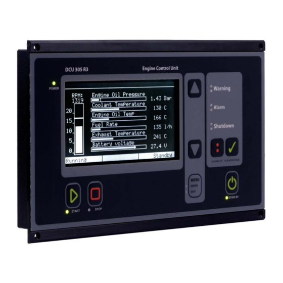
- Page 1 Installation Manual DCU 305 R3 DCU 305 R3 LT Diesel Engine Control Unit Auto-Maskin...
- Page 2 About this manual • ii...
-
Page 3: Table Of Contents
Content Document information ................. 5 Introduction ..................6 ........................6 BOUT THIS MANUAL DCU 305 R3 DCU 305 R3 LT ................6 BOUT THE ........................7 LASSIFIED SYSTEM ........................8 YSTEM VERVIEW ......................9 ONFIGURATION OVERVIEW ......................9 ECHNICAL PECIFICATIONS Cable connection ................ - Page 4 1 ......................35 AMPLE CHEMATIC 2 ......................36 AMPLE CHEMATIC MK-14 ...................... 37 PTIONAL ELAY AK-6 ....................38 PTIONAL NALOGUE ........................38 ABLE PECIFICATION Wire Terminal Tables ................. 40 RK-66 ......................40 WIRE TERMINAL UNIT MK-14 ........................42 ELAY UNIT AK-6 ........................
-
Page 5: Document Information
Information given in this document may change without prior notice. This document should not be copied without written permission from Auto-Maskin. All trademarks acknowledged. Related documents DCU 305 R3 & R3 LT User’s Manual DCU 305 R3 & R3 LT Communication Manual. RSP 305 Remote Panel. Rudolf R3 User’s Manual. -
Page 6: Introduction
For updated information, please contact your dealer. Assumptions This document describes the DCU 305 R3 and DU 305 R3 LT, and it will commonly be referred to as the DCU or the Control Unit. When referring to voltages, we always assume DC-voltages. When referring to AC-voltages it will be mentioned explicitly. -
Page 7: Classified System
The DCU 305 R3 LT is identical to the DCU 305 R3 with the exception that the LT version is without CAN bus capability. The DCU 305 R3 LT has the physical CAN bus port, but there is no support for CAN bus internally. -
Page 8: System Overview
The DCU 305 and the RK-66 is part of the standard delivery that makes a complete system. The other items are optional. Remote panel The optional RSP 305 Remote Panel can be added any time, as it communicates directly towards the DCU 305 R3, and is self- configuring. Page 8 (44) -
Page 9: Configuration Overview
For safety reasons, no parameters are adjustable without using the configuration tool Rudolf. No settings are necessary in the DCU 305 R3, nor in Rudolf, to connect and use the Rudolf program. Just connect the cable between your laptop PC and port P3 on the control unit. - Page 10 Part Value Weight Control unit: 1250g Protection level Front panel: IP54 Back panel: IP30 Ambient temperature Operation: 0-70°C Storage: -20-70°C Air humidity Operation: <90% Storage: Analogue alarm latency Built-in ~1 sec channels: Expansion card ~5 sec AK-6: RK-66 relays 120VAC 24VDC Notes The cables on the backpanel add to the overall depth.
-
Page 11: Cable Connection
“ground” whilst the battery negative is the 0V. and 0 volt! In the DCU 305 R3 system, +24V and 0V are filtered to ground using special filter components. This is done to avoid noise in the system. If ground and 0V is connected together, these filters do not work properly. - Page 12 Connect the two cables between the RK-66 and the control unit. The RK-66 wire terminal unit Now, connect the rest of the wires and complete the installation by connecting power to the supply inputs. Terminals 1 and 2 are for the start battery supply, and terminals 3 and 4 are from the auxiliary supply.
-
Page 13: Power Supply
20V. 12V supply installations The DCU 305 R3 is a 24V system, but can be used in 12V systems using an external DC/DC converter. The configuration in Rudolf must be switched to fit a 12V system. -
Page 14: Pickup Sensors
Pickup sensors Connect the pickup 1 between terminal 5 and 6. Please verify that the signal strength is between 2.5-30Vpp. Note: The pickup cable must be shielded to ground, not to 0V. Two pickups If two pickups are being used, connect the second pickup to terminal 65 and 66. - Page 15 Channel Broken Wire Backup on Warning, Alarm and Detection possibility Shutdown Shutdown possibility channels 7-12 Note: Do not connect +24V to the switch inputs! All input switches must be connected via its corresponding wire terminal to 0V, not to ground. Please see the schematic drawing page 35. Connecting the Switches Connect the warning, alarm and/or shutdown switches according to the project documentation and drawings.
-
Page 16: Analogue Input Channels
Example: a wire break detection installation on switch channel 1 should have a switch connected between terminal 7 (channel 1) and terminal 29 (0V reference) The 10k resistor must be connected across the switch, not across the terminals 7 and 29. Analogue Input Channels The control unit has five industrial-standard 4-20mA inputs. - Page 17 Note: Analogue channel one only, can be configured as a 0 channel. The dipswitch J12 inside the unit must be set as follows: 0-20mA / 4-20mA 0-10V Please note that this is applicable for analogue channel one only! Default setting is 0 20mA / 4-20mA.
-
Page 18: J1939 Can Connections
Minimum cable curve is 8x the cable diameter (ie it should not be bent too sharp). It must not be deformed in any way. On the DCU 305 R3 port P10, CAN_H is pin 7 and CAN_L is pin 2. No other pins should be connected. The shield should normally be connected at one end only, but in certain installations with a long cable it may be favorable to connect it at both ends. - Page 19 (which is common), each should have a 120ohm resistor connected at the end. The DCU 305 R3 has a 120ohm resistor internally. If the DCU is not at the end of the bus, a “CAN-card without J1” must be ordered and fitted.
-
Page 20: Miscellaneous Connections
Miscellaneous connections Please also refer to the schematics, page 35, for the following connections. Remote Start Remote Start works as the local Start Button. Connect terminal 31 to terminal 30 to engage. Remote Stop Remote Stop works as the local Stop Button, except it is immediate Connect terminal 32 to terminal 30 to engage. -
Page 21: The Automatic Fuses On The Rk-66 Module
The automatic fuses on the RK-66 module The RK-66 wire terminal card has six automatic fuses. Fuses F1, F2 and F5 are used by the DCU 305 R3 to secure internal circuits. These fuses are of type Raychem Polyswitch™ type RXE090. -
Page 22: Backup System Configuration
Rudolf R3. You may use these settings and skip this chapter entirely. Overview In the (unlikely) event of failure in the DCU 305 R3 main microcontroller, the built-in backup system will detect this, and activate the common alarm output relay. - Page 23 Pulses/Revolution, S1 and S2 Set the pulses/revolution on pickup #1 (connected to terminals 5 and 6) by switching the two rotary hex-switches S1 and S2 to the correct value. See the Appendix page Error! Bookmark not defined. for details. MS is the most significant value whereas LS is the least significant value.
-
Page 24: Built-In Alarms
The DIP-settings are for selection of the shutdown channels. All of the channels 1-6 that are configured as shutdown must have its corresponding DIP set to ON. In the example below, channels 1, 2 and 6 are set as shutdown channels. -
Page 25: Adjusting The Lcd Screen
Alarm text Comment Overspeed Engine running faster than the overspeed setpoint. Engine Stopped Engine stopped for no known reason. Engine failed to stop 60 seconds after issuing the stop command, the engine has still not stopped. Start Failure Engine failed to start after the last start attempt. Pickup failure Unable to read the pickup signal while engine is running. -
Page 26: Overspeed Test
Overspeed test This section describes how to enter the RPM Test mode. In test mode, the Overspeed Setpoint (typically 1725 rpm) is reduced to Nominal Setpoint (typically 1500 rpm). Note: The actual setpoints may vary from the above example. Consult the Rudolf configuration. -
Page 27: Optional Expansion Modules
In addition to the nine relays found on the RK-66 terminal board, an optional relay unit may be connected. The optional MK-14 unit, which add 14 relay channels to the DCU 305 R3. The function on each relay is configured using the configuration tool Rudolf R3. - Page 28 Available signals to the relay unit These are all the available signals in the DCU 305 R3 that can be routed to any of the relays on the relay cards. Relay K7 and K9 on the terminal card RK-66 are configurable in the same manner.
- Page 29 Signal Comment Preheat Preheating before and during start attempts. Stays on until engine has started or failed to start. Ready to start The genset is ready to start. Ready to take load The engine has reached the in Rudolf predefined rpm- setting.
-
Page 30: Analogue Unit Ak-6
Analogue unit AK-6 The analogue unit AK-6 connects directly into the DCU 305 R3. Another six 4-20 mA channels are then available in the control unit, to make a total of 11 channels. The unit has two 15-pin D-SUB connectors. One connects directly to the control unit. - Page 31 Connections The fifth analogue input on the RK-66 unit (terminal 27 and 28) becomes the first analogue input on the AK-6 card. If there is a connection at terminal 27 and 28 on the RK-66 card, move these to terminal 1 and 2 on the AK-6 card. Consider the following table when using the AK-6 analogue expansion unit.
-
Page 32: Communication
In addition the DCU 305 R3 has the J1939 CAN bus communication protocol built-in. On the DCU 305 R3 port P10 is dedicated to CAN communication. For further description, please see installation manual for DCU 305 R3. -
Page 33: Multidrop Communication
Port P3 The DCU 305 R3 has a 9-pin D-SUB male connector at port P3, outlined as follows: Pin # Description Port P10: The DCU 305 R3 has a 9-pin D-SUB male connector at port P10, outlined as follows: Pin #... -
Page 34: Retrieve The Log To Apc
Retrieve the log to a PC The built-in event log in the control unit can be retrieved with simple means. • Connect the configuration software to the DCU 305 R3 using the Rudolf cable. • In the configuration software, select Communication –... -
Page 35: Schematic Drawings
Schematic Drawings Sample Schematic Page 1 Page 35 (44) -
Page 36: Sample Schematic
Sample Schematic Page 2 Page 36 (44) -
Page 37: Optional Relay Unit Mk-14
Optional Relay Unit MK-14 Page 37 (44) -
Page 38: Optional Analogue Unit Ak-6
Optional Analogue Unit AK-6 Page 38 (44) -
Page 39: Cable Specification
- Rudolf Configuration Shield to be connected Shielded cable 0.20 mm to DSUB housing at Separate cable Comli/Modbus communication DCU 305 R3 end only DSUB AK-6, MK-14, Shield to be connected Shielded cable 0.20 mm C1-C2-C3 cable to DSUB housing at... -
Page 40: Wire Terminal Tables
Wire Terminal Tables RK-66 wire terminal unit DCU 305 R3 (RK-66) Comment +24V Primary supply. Connect to start battery. +24V Secondary supply. Connect to auxiliary supply. Pickup 1 Used when one pickup only. Pickup 1 2.5 - 30Vpp. Switch input 1... - Page 41 DCU 305 R3 (RK-66) Comment Analogue Input 5, 4-20mA Common 0V Common 0V Remote Start Connect to terminal 30 to activate Remote Stop Connect to terminal 30 to activate Common 0V Blackout Start Connect to terminal 33 to activate Delayed Stop...
-
Page 42: Relay Unit Mk-14
Config input 1 Configurable input. Config input 2 Configurable input. Power-on Connect to +24V to power-on in parallel with the keyswitch found on DCU 305 R3 P. Reserved input For future expansion Pickup 2 For pickup 2. Pickup 2 Use Pickup 1 inputs if there is one pickup only. 2.5-30Vpp. -
Page 43: Analogue Unit Ak-6
Relay Terminal Relay Relay 9, C Relay 9, NC Relay 9, NO Relay 10, C Relay 10, NC Relay 10, NO Relay 11, C Relay 11, NC Relay 11, NO Relay 12, C Relay 12, NC Relay 12, NO Relay 13, C Relay 13, NC Relay 13, NO K14 #1... - Page 44 Terminal AI channel Signal type +24V supply 4-20mA input +24V supply 4-20mA input +24V supply 4-20mA input Connect to RK-66 terminal 27 Connect to RK-66 terminal 28 Connect to RK-66 terminal 29 *) Connect these three wires between RK-66 and AK-6. Page 44 (44)
Need help?
Do you have a question about the DCU 305 R3 and is the answer not in the manual?
Questions and answers