Advertisement
Quick Links
Advertisement

Related Manuals for auto maskin DCU 305 R3 LT


Summary of Contents for auto maskin DCU 305 R3 LT
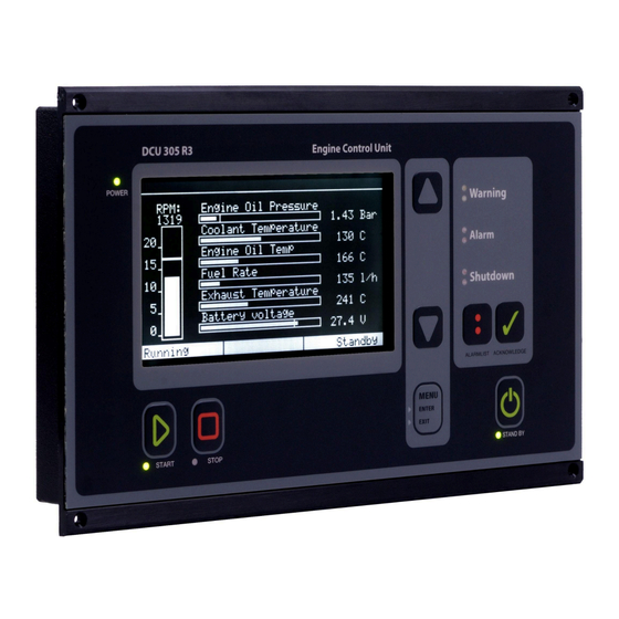
- Page 1 Publication P/N 1501342 DCU 305 R3 LT Engine Controller Installation Manual...
- Page 2 DCU 305 R3 LT Engine Controller Installation Manual Table of contents 5.3 Configuration of DIP Switches....20 1 Document revisions..........3 6 Internal Alarms........... 21 2 Introduction............4 7 Overspeed Test..........22 2.1 About this Manual........4 7.1 Enter the RPM Test Mode......22 2.2 Responsibilities..........
- Page 3 Created November 2007 Minor adaptations for firmware 6.53 and onwards, because of a new menu layout. July 2014 Added support for the DCU 305 R3 LT, including picture updates August 2020 Sample Schematic Page 1 updated December 2024 Revised document Copyright ©...
- Page 4 2.3 Reference This installation manual is for the two engine controllers, DCU 305 R3 and DCU 305 R3 LT. The manual commonly refers to these panels as the DCU or Engine Controller. The RK-66 Interface Module may be referenced as the Interface Module.
- Page 5 Each project is unique, and the DCU 305 R3 is configured using a configuration tool for Windows®, the Rudolf R3™ software. Note! The DCU 305 R3 LT is identical to the DCU 305 R3 except that the LT version does not support the J1939 CAN bus.
- Page 6 DCU 305 R3 LT Engine Controller Installation Manual 3 System Overview The engine monitoring system's basic components are the DCU 305 Engine Controller and the RK-66 Interface Module. Optional analogue units and relay cards may be added to expand the I/O capability and overall flexibility.
- Page 7 DCU 305 R3 LT Engine Controller Installation Manual 3.2 RK-66 Interface Module All wires and sensors shall be connected to the RK-66 Interface Module, which is a mandatory unit in all installations. 3.3 MK-6/14 Relay Expansion Units The MK-6 and the MK-14 Relay Expansion Units add 6 or 14 relays to the system.
- Page 8 DCU 305 R3 LT Engine Controller Installation Manual 3.6 Communication The DCU 305 Engine Controllers support the Modbus protocol for communication. For more information, see the DCU 305 R3 Communication Manual. 3.7 Configuration The engine controller is fully customised using the Rudolf R3™ configuration software for Windows.
- Page 9 DCU 305 R3 LT Engine Controller Installation Manual Connect the Rudolf Cable between the laptop PC and port P3 on the engine controller to start configuring. Rudolf Cable Note! If the laptop does not have an RS-232 port, add the USB-A to RS-232 cable.
- Page 10 DCU 305 R3 LT Engine Controller Installation Manual 4 Wire Connections All wire connections are made on the RK-66 Interface Module. 4.1 In General To protect against EMC noise, we recommend that all cables be shielded. The shield of all cables shall be connected to the ground, not to 0V. Some cables shall be grounded on one end only, while others shall be grounded on both ends.
- Page 11 DCU 305 R3 LT Engine Controller Installation Manual The RK-66 wire terminal unit Now, connect the rest of the wires and complete the installation by connecting power to the supply inputs. Terminals 1 and 2 are for the start battery supply, and terminals 3 and 4 are for the auxiliary power supply.
- Page 12 DCU 305 R3 LT Engine Controller Installation Manual 4.4 Power Supply 4.4.1 24V Supply Use a twisted pair wire to minimize the effect of electrical disturbances on the cable. The start battery power shall be connected to the primary supply on terminals 1 and 2.
- Page 13 DCU 305 R3 LT Engine Controller Installation Manual 4.6 Pickup Sensors Note! The pickup cable shall be shielded to the ground, not to 0V. 4.6.1 One pickup in use Connect pickup 1 between terminals 5 and 6. Please verify that the signal strength is between 2.5-30 Vpp.
- Page 14 DCU 305 R3 LT Engine Controller Installation Manual Note! Do not connect +24V to the switch inputs. All input switches shall be connected via their corresponding wire terminal to 0V, not to ground. 4.7.1 Wire break detection Channels 1-6 can detect wire breaks. This is useful when the channel is being used as a shutdown channel.
- Page 15 The alarm Analog Sensor Failure appears if an enabled analogue channel is not connected or if the signal strength is too low (<2 mA). Optional analog expansion module Not on the DCU 305 R3 LT, only supported on the 305 R3 Default factory setting Page 15 (40)
- Page 16 DCU 305 R3 LT Engine Controller Installation Manual Instead of a numeric value to the right of the bargraph, the sign “----“ will be displayed, for instance like this: Oil Pressure –--- Bar Note! If 0-10 V or 0-20 mA is selected, the analogue Sensor Failure alarm is disabled.
- Page 17 DCU 305 R3 LT Engine Controller Installation Manual The minimum cable curve is 8x the cable diameter (i.e., it should not be bent too sharp) and must not be deformed in any way. On the DCU 305 R3 port P10, CAN_H is pin 7, and CAN_L is pin 2. No other pins should be connected.
- Page 18 DCU 305 R3 LT Engine Controller Installation Manual 4.9.6 The CAN-repeater and shield When utilising CAN-repeaters, the shields must not be connected to the new cable. 4.10 Miscellaneous Connections 4.10.1 Remote Start Remote Start works in the same way as the local Start Button.
- Page 19 DCU 305 R3 LT Engine Controller Installation Manual Note! For this feature to work, the jumper J1 inside the main unit must be removed. With the jumper ON, the engine controller is always powered. To remove jumper J1, remove the back lid. It is located in the bottom left corner.
- Page 20 DCU 305 R3 LT Engine Controller Installation Manual 5 Backup System Configuration The DCU 305 R3 has a redundant backup system that is always on. 5.1 Overview In the (unlikely) event of failure in the DCU 305 R3 main microprocessor, the built-in backup system will detect this and activate the common alarm output relay.
- Page 21 DCU 305 R3 LT Engine Controller Installation Manual Example dialog for Backup System Setting. 6 Internal Alarms The DCU 305 R3 Engine Controller has several internal alarms, as outlined in the table below. Alarm text Comment Low battery voltage Low voltage at the start battery.
- Page 22 DCU 305 R3 LT Engine Controller Installation Manual 7 Overspeed Test This section describes how to enter the RPM Test mode. In test mode, the Overspeed Setpoint (typically 1725 RPM) is reduced to the Nominal Setpoint (typically 1500 RPM). Note! The actual setpoints may vary from the above example. Consult the Rudolf R3 configuration for the project in question.
- Page 23 DCU 305 R3 LT Engine Controller Installation Manual 8 Optional Expansion Modules The DCU 305 Series has a few optional expansion modules, to expand the overall I/O capability. 8.1 MK-6 and MK-14 Relay Expansion Unit In addition to the nine relays on the RK-66 Interface Module, an optional relay unit may be connected, adding 6 or 14 relays to the system.
- Page 24 DCU 305 R3 LT Engine Controller Installation Manual 8.1.2 Available relay unit functions These are all the available functions in the DCU 305 R3 that can be routed to any relay on the MK-6 and MK-14 relay expansion units. Note! Relays K7 and K9 on the RK-66 Interface Module are also configurable.
- Page 25 DCU 305 R3 LT Engine Controller Installation Manual Function Comment Preheat Preheating before and during start attempts. Stays on until the engine has started or failed to start. Ready to start The genset is ready to start. Ready to take the load The engine has reached the predefined RPM setpoint.
- Page 26 DCU 305 R3 LT Engine Controller Installation Manual AK-6 The update time for the six expansion channels is somewhat longer than for the five standard channels. The standard channel five will also have a longer update interval when the AK-6 is used. Therefore, we recommend connecting mostly “slow” media, e.g., temp transmitters, to the AK-6 card.
- Page 27 DCU 305 R3 LT Engine Controller Installation Manual RK-66 terminal # AK-6 terminal # Channel page +24V 4-20 mA +24V 4-20 mA On the AK-6, connect terminals 27, 28 and 29 directly to terminals 27, 28 and 29 on the RK-66.
- Page 28 DCU 305 R3 LT Engine Controller Installation Manual 9 Communication The information from sensors and switches connected to the DCU 305 R3 can be remotely monitored by utilising the built-in communication channel. Any common supervision systems, such as Factory Link®, InTouch®, etc. that support the Comli or Modbus RTU protocol can be used.
- Page 29 DCU 305 R3 LT Engine Controller Installation Manual 9.1.2 Port P10 The DCU 305 R3 has a 9-pin D-SUB male connector at port P10, outlined as follows. Pin # Description CAN-L CAN-H 9.2 Multidrop Communication Several DCU 305 R3 units may be connected in a multidrop network. Two typical scenarios exist.
- Page 30 DCU 305 R3 LT Engine Controller Installation Manual 10 Wiring Tables This chapter describes the wiring of the three modules ● RK-66 Interface Module (mandatory) ● MK-6 and MK-14 Relay Expansion ● AK-6 Analog Expansion 10.1 RK-66 Interface Module DCU 305 R3 (RK-66)
- Page 31 DCU 305 R3 LT Engine Controller Installation Manual DCU 305 R3 (RK-66) Comment +24V Output, protected by fuse F6 Analog Input 2, 4-20 mA +24V Output, protected by fuse F6 Analog Input 3, 4-20 mA +24V Output, protected by fuse F6...
- Page 32 DCU 305 R3 LT Engine Controller Installation Manual DCU 305 R3 (RK-66) Comment To Stop Solenoid, Relay K2. +24V +24V supply to auxiliary stop relay To Run Solenoid, Relay K3. +24V +24V supply to auxiliary run relay To Shutdown Solenoid Relay K4.
- Page 33 DCU 305 R3 LT Engine Controller Installation Manual DCU 305 R3 (RK-66) Comment Pickup 2 For pickup 2. Use Pickup 1 inputs if there is one pickup only. 2.5-30Vpp. Pickup 2 10.2 MK-6 and MK-14 Relay Expansion Unit The function on these optional relays is user-defined using the Rudolf R3 configuration software.
- Page 34 DCU 305 R3 LT Engine Controller Installation Manual Relay Terminal Relay Relay 9, NC Relay 9, NO Relay 10, C Relay 10, NC Relay 10, NO Relay 11, C Relay 11, NC Relay 11, NO Relay 12, C Relay 12, NC...
- Page 35 DCU 305 R3 LT Engine Controller Installation Manual Terminal AI channel Signal type 4-20 mA input +24V supply 4-20 mA input +24V supply 4-20 mA input +24V supply 4-20 mA input Connect to RK-66 terminal 27 Connect to RK-66 terminal 28...
- Page 36 DCU 305 R3 LT Engine Controller Installation Manual 11 Cable Specification When wiring the RK-66 Interface Module, use wires and cables as specified below. Terminal Function Cable specification Comment Primary 24VDC supply Twisted pair 1.5 mm Secondary 24VDC Twisted pair 1.5 mm...
- Page 37 DCU 305 R3 LT Engine Controller Installation Manual Terminal Function Cable specification Comment Separate cable GND at both ends DSUB - Rudolf Configuration Shielded cable 0.20 mm Shield to be connected to DSUB housing at DCU 305 R3 - Comli/Modbus...
- Page 38 DCU 305 R3 LT Engine Controller Installation Manual 12 Schematics Page 38 (40)
- Page 39 DCU 305 R3 LT Engine Controller Installation Manual Schematics page 2 Page 39 (40)
- Page 40 DCU 305 R3 LT Engine Controller Installation Manual Schematics optional units, AK-6 and MK-14/MK-6 Page 40 (40)
Need help?
Do you have a question about the DCU 305 R3 LT and is the answer not in the manual?
Questions and answers