auto maskin RP 410E Installation Manual
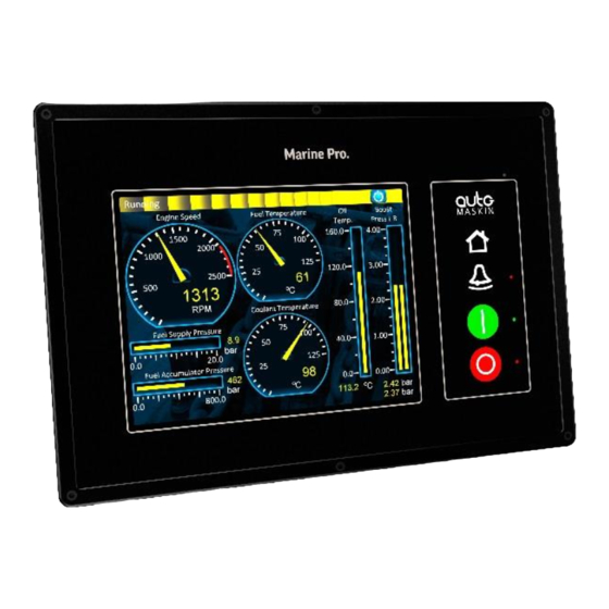
Marine pro 400e series.
engine control unit
remote panel
Hide thumbs
Also See for RP 410E:
- Configuration manual (99 pages) ,
- Quick installation manual (2 pages)

Related Manuals for auto maskin RP 410E


Summary of Contents for auto maskin RP 410E
- Page 1 Manual# 1100346 Installation Manual 400E Series DCU 410E – Engine Control Unit RP 410E – Remote Panel RP 410E DCU 410E...
- Page 2 Copyright © 2017 by Auto-Maskin AS. All rights reserved. No part of this document may be reproduced or transmitted in any form or by any means, electronic, mechanical, photocopying, recording, or otherwise, without the prior written permission of Auto-Maskin AS. Installation Manual – 400E Series...
-
Page 3: Table Of Contents
Table of Content DOCUMENT INFORMATION ........ 1 Common Alarm Relay [73 – 75] ....13 Shutdown Output [79] ......... 13 ..........1 BOUT THIS MANUAL ETS – Energize to Stop [80] ......13 Responsibilities ..........1 ETR – Energize to Run [81] ......13 ........ -
Page 4: Document Information
The user of this material is assumed to have basic knowledge in marine Note! Auto-Maskin continuously systems, and must be able to carry out upgrades its products and reserves the related electrical work. right to make changes and Work on the low voltage circuit should improvements without prior notice. -
Page 5: 400E Series Overview
400E Series Overview The RP remote panel can monitor and Typical Layout control everything in the DCU from a remote location. It has the same user interface configures automatically The following shows a typical layout. according to the DCU. The DCU 410E is the main building For classed installations the SDU safety block in the 400 Series. -
Page 6: Available Units In The 400 Series
When connected, a new page is made available on the DCU – and on the Available units in the remote panel RP 410E – that displays 400 Series generator parameters such as phase voltages, phase currents, frequency, power, efficiency factor (Cos phi), etc. -
Page 7: Precautions In Classed Systems
DCU primary supply. Certification All modules in the 400 Series are certified by major classification societies. Certificates can be obtained from the Auto-Maskin website, or from your local distributor. Installation Manual – 400E Series Page 4... -
Page 8: Installation
In a ship installation, the hull is the Measurements and Weight “ground” whilst the battery minus is the DCU 410E RP 410E Width Height Depth Width Height Depth Size [mm] Cutout [mm] 2 mm added to actual... -
Page 9: Dcu Rear Lid Layout
DCU Rear Lid Layout SDU & RIO Link Modbus RTU, CAN1&2 Relay 1 Relay 2 PT100 Config All Faults Relay Config 4-20mA Shutdown ETS, ETR Running Crank Prelube 24V 50mA Switch Inputs / Opto. Fixed Functional Inputs / Opto. 24V/ 40mA COM8 Relay... -
Page 10: Dcu Wire Terminal Layout Overview
0V For Switch Input DCU Wire Terminal 4-20 mA Inputs (4 channels) Layout Overview +24VDC 0.2A Supply for 4-20 mA Sensors Power supply inputs /auxiliary power output #1 4-20 mA Input +24VDC Primary Supply #2 4-20 mA Input 0V Primary Supply #3 4-20 mA Input +24VDC Secondary Supply #4 4-20 mA Input... - Page 11 Modbus H Engine Running 24VDC Modbus +24VDC Supply Crank (Start) 24VDC RIO 410 Remote I/O Interface (COM 2) Prelube Activation 24VDC RIO 410 Remote I/O Interface Fixed 24VDC Inputs Shield +24VDC Supply for Fixed RIO 410 Remote I/O Interface L Functional Inputs RIO 410 Remote I/O Interface H Prelube Complete 24VDC switch...
-
Page 12: Dcu Electrical Connections
Without a separate secondary supply, a DCU Electrical crank can result in a reboot of the DCU. However if only one supply is available, Connections connect this to Pimary only. Do not parallel this into the Secondary Power Supply Primary Power Supply [1 – 2] connectors. -
Page 13: Auxiliary Power Output [5 - 6]
The Auxiliary supply is secured with an Supply Selection automatic fuse. The DCU internal circuitry is sourced from either the primary OR the System On/Off [7 – 10] secondary supply. The DCU has a System On/Off function. The primary supply has priority over System On is the normal mode of the secondary supply. -
Page 14: Power Output [11]
The 24VDC on terminal 16 shall be 5V Power Output [11] used for the switch input supply. It is This 5V Power Output is a general secured with a 200 mA automatic fuse. purpose supply for maximum 0.5A load and Short-Circuit protection. Normal Use shall Terminals 25 and 26... -
Page 15: Magnetic Pickup (Speed) Sensor
<90 ohm (short) Terminal 51 - CAN High >390 ohm (broken) MODBUS RTU, RS-485 (COM 3) Update rate: 2 Hz [52 – 56] Magnetic Pickup (Speed) Sensor The MODBUS RTU may be connected [44 – 45] either with common 0V or electrically isolated with an optocoupler. -
Page 16: Configurable Relays [63 - 68]
Terminal 62 - High It does not activate for a normal engine stop. Configurable Relays [63 – 68] ETS – Energize to Stop [80] There are two configurable relays on the DCU, Relay 1 and Relay 2. Each The ETS activates on a normal engine relay may be enabled or disabled. -
Page 17: Supply For Fixed Function Inputs [85]
24V Supply for Fixed Function Automatic Stop [90] Inputs [85] Apply this signal to stop the engine according to the DCU stop Use this 24V supply output to power all configuration. the inputs in the wire terminal range 86 to 97. Note that this terminal input is disabled if Automatic Mode [88] is Prelube Comp. -
Page 18: In Gear [95]
On the SDU, the SO is activated by Note! Keep this wire as short as closing a switch over terminals 50 possible, and at least 1.5mm2. and 51. Note that the switch Terminals 46, 49, 53, 57, 60 and 100 requires a 10k resistor connected are all ground connections, internally across it. - Page 19 It can also be used to load a new The function to be present at each firmware file to any connected RP 410E relay channel is configured in the DCU remote panel. web server. Select Home – MK-14.
-
Page 20: Rp Rear Lid Layout
RP Rear Lid Layout Audio Line Out COM 3, Modbus Ethernet Relay Exp. MK-14 Power, Switch Inputs, Relay 1, Relay 2, Relay 3, Relay 4, COM1, COM2, C-GND Installation Manual – 400E Series Page 17... -
Page 21: Rp Wire Terminal Layout Overview
#4 Configurable Relay C RP Wire Terminal #4 Configurable Relay NO Layout Overview RS-232 (COM 1) Power supply inputs /auxiliary power output +24VDC Primary Supply 0V Primary Supply Switch Inputs Channels (4 channels) +24VDC 0.2A Supply for Switch Inputs RS-232 (COM 2) #1 Switch Input 24V #2 Switch Input 24V #3 Switch Input 24V... -
Page 22: Rp Electrical Connections
Switch Input Channels [3 – 7] RP Electrical There are four configurable switch Connections input channels which can be used to detect the status of switches in the A minimum installation requires only installation. power supply to terminals 1-2, and an The state of each channel is controlled Ethernet cable to the DCU. -
Page 23: Com 1/ Rs-232 [20 - 24]
COM 1/ RS-232 [20 – 24] First Power-On General purpose RS-232 Port with RTS and CTS support. Preparations Installation COM 2/ RS-232 [25 – 27] Install the RP according to guidelines and suggestions. General purpose RS-232 Port. Connections Connect power according to guidelines Shield (Grounding) [28] and suggestions.
Need help?
Do you have a question about the RP 410E and is the answer not in the manual?
Questions and answers