Table of Contents
Advertisement
Quick Links
Advertisement
Table of Contents

Related Manuals for auto maskin DCU 305 R3


Summary of Contents for auto maskin DCU 305 R3
- Page 1 User’s Manual DCU 305 R3 DCU 305 R3 LT Diesel Engine Control Unit Auto-Maskin...
-
Page 2: Table Of Contents
Content Document information Introduction BOUT THIS MANUAL DCU 305 R3 & R3 LT BOUT THE ERTIFICATES ECHNICAL PECIFICATIONS Using the DCU 305 R3 HE DIFFERENT VIEWS HE MENU OPTIONS UILT LARMS RONTPANEL UTTONS Communication ROTOCOL AND PIN CONFIGURATION ULTIDROP COMMUNICATION... -
Page 3: Document Information
Copyright © Auto-Maskin AS, 2014 Information given in this document may change without prior notice. This document should not be copied without written permission from Auto-Maskin. Title: DCU 305 R3 & R3 LT User's Manual This Revision: July 2014 All trademarks acknowledged. -
Page 4: Introduction
For updated information, please contact your dealer or Auto-Maskin directly. Assumptions This document describes the DCU 305 R3. The unit can be used in Auxiliary or Propulsion installations. The unit will be referred to as the Control Unit. When referring to voltages, always assume DC-voltages. When referring to AC-voltages it will be mentioned explicit. -
Page 5: Certificates
Communication is built-in and ready for use towards slave panels on the bridge. The DCU 305 R3 LT is identical to the DCU 305 R3 with the exception that the LT version do not have the CAN capability. Certificates The DCU 305 R3 is classified by the following classification societies. -
Page 6: Technical Specifications
Technical Specifications Part Value Overall dimensions (1) 160 x 260 x 35 mm (H x W x D) Cut-out dimensions 146 x 230 mm (H x W) Supply voltage (2) 24V smoothed, (20 – 35V DC) Power consumption (3) 500mA/12W @24V DC Weight Control unit: 1250g... -
Page 7: Using The Dcu 305 R3
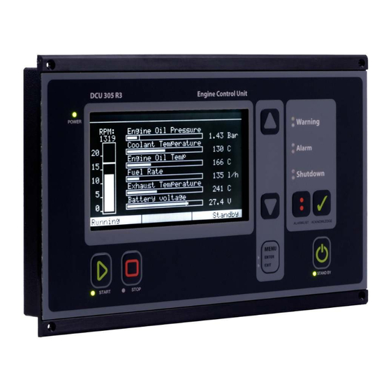
Using the DCU 305 R3 The different views The DCU 305 R3 has several screens or views. These are: Menu view Instrument view Alarm list view Information view Event Log view CAN status/restart view. Diagnostic display view Menu To enter menu view, press the menu button. - Page 8 Instrument The instrument view is the DCU 305 R3’s main view. EXIT in the menu will always lead to instrument view. The RPM indicator and the battery voltage are always displayed. The bottom line is divided into three status fields.
- Page 9 If the optional analogue card AK-6 is used, pressing the down arrow button will reveal the next six channels. RPM indicator To the left of the screen is the speed indicator bar, with the actual RPM showing at the top of the bar. The overspeed setpoint is marked with a double horizontal line.
- Page 10 Static project- related information Various timers and counters Current software version (DCU 305 R3) Information view The bottom half of the picture displays various timers and counters. The Operation Mode is listed, along with the following counters: Engine hours (0-65535 hours) Previous running hours (“trip”...
-
Page 11: Event Log
Diagnostic Message Text. When no SPN and FMI’s are active, the screen is empty. DIAGNOSTIC DISPLAY 1 FAULT 1>SPN 91 FMI: 8 Throttle signal. Invalid or Abnormal signal, or Fault. Example: DCU 305 R3 Diagnostic Display view – 1 Diagnose is active. Page 10 (20) -
Page 12: The Menu Options
DIAGNOSTIC DISPLAY EXIT DCU 305 R3 menu view – cursor at INFORMATION. To enter the different views or functions from the menu, use the up- or down arrow button to place the cursor in front of the desired view, press menu button to select. - Page 13 The new setting is automatically stored in internal memory, and stays resident regardless of future power loss. Note: To preserve LCD lifetime, the display automatically shuts off after the configured amount of time, if no action has been observed in that period.
-
Page 14: The Built-In Alarms
RPM Test This section describes how to enter the RPM-test mode. In test mode, the Overspeed Setpoint (typically 1725 rpm) is reduced to Nominal Setpoint (typically 1500 rpm). From the menu view, follow these steps to enter the RPM-test mode: Use the up- or down arrow-button to place the cursor in front of RPM TEST Press the menu button once to activate RPM test... -
Page 15: Frontpanel Buttons
Alarm text Comment Output circuit overload Short circuit in one of the +24V outputs terminals 41-44. The outputs are secured with a fuse that makes an automatic reset. Remove the overload to correct the problem. Analogue sensor failure [7] Detailed information on which analog channel that is below 2mA. - Page 16 The rightmost Status field also indicates the chosen mode by displaying either “Standby” or ”Manual”. Standby mode The control unit will initiate the automatic start sequence when receiving the Blackout Signal on terminal 34. It starts the engine (with the number of start attempts configured) and then waits for the Delayed Stop signal to initiate automatic stop.
- Page 17 Enter When green light in the menu button is lit, it is possible to select the different options in the menu. Exit A yellow light is lit in the menu button when the display shows info view, event log view or alarm list view. When pressing the menu button the display will escape to instrument view (main view) Alarm list button...
-
Page 18: Communication
In addition the DCU 305 R3 has the J1939 CAN-bus communication protocol built-in. On the DCU 305 R3 port P10 is dedicated to CAN communication. For further description, please see installation manual for DCU 305 R3. -
Page 19: Multidrop Communication
Port P3 The DCU 305 R3 has a 9-pin D-SUB male connector at port P3, outlined as follows: Pin # Description Port P10: The DCU 305 R3 has a 9-pin D-SUB male connector at port P10, outlined as follows: Pin #... -
Page 20: Retrieve The Log To Apc
Retrieve the log to a PC The built-in event log in the control unit can be retrieved with simple means. • Connect the configuration software to the DCU 305 R3 using the Rudolf cable. • In the configuration software, select Communication – Retrieve Log…...
Need help?
Do you have a question about the DCU 305 R3 and is the answer not in the manual?
Questions and answers