Table of Contents
Advertisement
Advertisement
Table of Contents

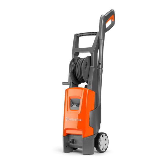
Summary of Contents for Husqvarna PW 235
- Page 1 Workshop manual PW 235 PW 235R English...
-
Page 2: Table Of Contents
4.2.2 Start up-pressure build up ........13 4.2.3 Pressure build up-opening pressure/close gun ..14 4.2.4 Motor stop - standby pressure ......14 4.2.5 Gun is activated ..........15 4.2.6 Machine run ............15 4.3 Wiring diagram PW 235 ..........16 4.4 Wiring diagram PW 235R ..........17 2 – English... -
Page 3: Introduction And Safety Regulations
Introduction and safety regulations 1 Introduction and safety regulations 1.1 General 1.4.2 Special safety instructions This workshop manual gives a full description of how to WARNING: Do not use accessories and/or do troubleshooting, repair and test of the high pressure do changes that are not approved by the washer. -
Page 4: Repair Instructions
Repair instructions 2 Repair instructions 2.1 Product overview, Cabinet torque 1,5 Nm 1,2 Nm 1,5 Nm 1,2 Nm 1,5 Nm 4 – English... -
Page 5: Product Overview, Pump Unit Torque
Repair instructions 2.2 Product overview, Pump unit torque 8 Nm 18 Nm 16 Nm 10 Nm 8 Nm 8 Nm English – 5... -
Page 6: To Disassemble/Assemble The Front Cabinet And Accessory Storage
Repair instructions 2.3 To disassemble/assemble the 4. Loosen the front cabinet from the accessories storage. Use a screwdriver on both sides, see figure front cabinet and accessory storage below. Remove the accessories storage. 1. Tools: Torx 20 screwdriver and flat screwdriver. 5. -
Page 7: To Disassemble/Assemble The Control Unit And/Or Wireless Unit
Repair instructions 2.4 To disassemble/assemble the 2.5 To pair the product and the control unit and/or wireless unit* handle* Tools: Torx 9 screwdriver. * PW 235R version only Pairing of the wireless devices is needed if: • The handle has been exchanged. •... -
Page 8: To Disassemble/Assemble The Motor Cover
Repair instructions 2.7 To disassemble/assemble the motor cover 1. Put the product on the side and remove the 4 torx 20 screws. 2. Remove the wheel to remove the 5th screw. The micro switch box can be removed by hand. 4. -
Page 9: To Disassemble/Assemble The Water/Oil Seal And Valves
Repair instructions 2.9 To disassemble/assemble the 2. The figure below shows the pump after opening the cylinder head from the cylinder block. water/oil seal and valves 1. To change the oil seals, water seals and pressure valve, use a screw driver to disassemble the parts. Alternatively use a puller, part number 592 94 49-01, to pull out the valves seats (pressure and suction valves). - Page 10 Repair instructions CAUTION: Make sure to position the valve bodies correctly according to the water canals inside the cylinder head. This is to optimize the self suction mode. The “leg” of the valve body must not be placed in front of a canal.
-
Page 11: Specifications
Specifications 3 Specifications 3.1 Technical data Value PW 235/PW 235R Specification Max 130 bar Voltage 230 V Frequency 50 Hz Power consumtion 7.8 A Power absorbed 1.8 kW Number of revolutions 17,000-18,000 rpm./min. Water volume, HP 5.3-6.3 l/min Pump pressure... -
Page 12: Appendices And Schemas
The pump is filled with 80 ml LHM 32 from the production. In case of service where the oil must be changed, Husqvarna recommends to use 80 ml Bartran HV 46. Alternative oil types that are allowed: • BP, Bartram HV 46 •... -
Page 13: Start Stop System Guide
Appendices and schedules 4.2 Start stop System guide 4.2.1 No pressure in system No pressure in system - except inlet pressure 3 bar. Machine switch off. Pump 3 BAR Non return valve Inlet 3 BAR Outlet 3 Bar 4.2.2 Start up-pressure build up Machine switch on / Start up - Pressure build up Pump >5 BAR... -
Page 14: Pressure Build Up-Opening Pressure/Close Gun
Appendices and schedules 4.2.3 Pressure build up-opening pressure/close gun Gun close. Pressure build up. Opening pressure. Micro switch is activated Pump 130 BAR Non return valve Inlet 3 BAR 130 BAR Outlet 4.2.4 Motor stop - standby pressure Gun close. Motor stops. Pressure in hose decreases to standby pressure Pump pressure is also standby pressure. -
Page 15: Gun Is Activated
Appendices and schedules 4.2.5 Gun is activated Gun is open - Control piston is closed. Micro switch is deactivated. Motor starts. Pump 3 BAR Non return valve Inlet 3 BAR Outlet 3 BAR 4.2.6 Machine run Machine runs (normal working pressure). Gun is open. Pump 100 BAR Non return valve... -
Page 16: Wiring Diagram Pw 235
Appendices and schedules 4.3 Wiring diagram PW 235 Wiring diagram Circuit diagram br[ro] bl[hv] S2M Switch Thermo 140° 2a c1 Brown Blue Black Yellow White Capacitor Switch Single-pole switch/ micro switch Control unit Motor 16 – English... -
Page 17: Wiring Diagram Pw 235R
Appendices and schedules 4.4 Wiring diagram PW 235R Circuit diagram Wiring diagram br[so] bl[hv] S2M Switch Thermo 140° Brown Blue Black Yellow White Capacitor Switch Single-pole switch/ micro switch Control unit Motor English – 17... - Page 18 115 97 59-26 2017–11–23...


Need help?
Do you have a question about the PW 235 and is the answer not in the manual?
Questions and answers