Table of Contents
Advertisement
Advertisement
Table of Contents

Related Manuals for virtual access GW6600 Series


Summary of Contents for virtual access GW6600 Series
- Page 1 GW6600 Series User manual Issue: Date: 13 July 2018...
-
Page 2: Table Of Contents
Connecting the WiFi antenna ..............18 2.15 Powering up ................... 18 2.16 Reset button ..................18 GW6600 Series LED behaviour ..............19 Main LED behaviour................. 19 Ethernet port LED behaviour ..............21 Factory configuration extraction from SIM card ......... 22 Accessing the router ................... 23 Configuration packages used .............. - Page 3 Maximum number of VLANs supported ............ 107 11.2 Configuration package used ..............107 11.3 Configuring VLAN using the web interface ..........107 11.4 Viewing VLAN interface settings .............. 110 _______________________________________________________________________________________________________ © Virtual Access 2018 GW6600 Series User manual Issue: 1.7 Page 3 of 519...
- Page 4 GRE configuration using command line ............ 175 16.4 GRE configuration using UCI ..............175 16.5 GRE configuration using package options ..........175 16.6 GRE diagnostics ..................176 _______________________________________________________________________________________________________ © Virtual Access 2018 GW6600 Series User manual Issue: 1.7 Page 4 of 519...
- Page 5 Configuration package used ..............223 22.3 Configuring RIP using the web interface ........... 224 22.4 Configuring RIP using command line ............228 22.5 RIP diagnostics ..................232 _______________________________________________________________________________________________________ © Virtual Access 2018 GW6600 Series User manual Issue: 1.7 Page 5 of 519...
- Page 6 Configuring Dynamic DNS using the web interface ........316 29.4 Dynamic DNS using UCI................. 318 30 Configuring hostnames ................320 30.1 Overview ..................... 320 30.2 Local host file records ................320 _______________________________________________________________________________________________________ © Virtual Access 2018 GW6600 Series User manual Issue: 1.7 Page 6 of 519...
- Page 7 Configuring QoS using the web interface ..........389 36.4 Configuring QoS using UCI ..............391 36.5 Example QoS configurations ..............394 37 Management configuration settings ............395 37.1 Activator ....................395 _______________________________________________________________________________________________________ © Virtual Access 2018 GW6600 Series User manual Issue: 1.7 Page 7 of 519...
- Page 8 Configuring data usage using the web interface ........463 41.4 Data usage status ................. 466 41.5 Data usage diagnostics ................466 42 Configuring Terminal Server ..............468 42.1 Overview ..................... 468 _______________________________________________________________________________________________________ © Virtual Access 2018 GW6600 Series User manual Issue: 1.7 Page 8 of 519...
- Page 9 43 Configuring SAToP and CESoPSN .............. 485 43.1 What are SAToP and CESoPSN? .............. 485 43.2 Clocking ....................485 43.3 Virtual Access proprietary SAToP/CESoPSN protocol extension ....486 43.4 Configuration package used ..............486 43.5 Configuring SAToP/CESoPSN ..............487 43.6 Configuring main settings using UCI ............
-
Page 10: Introduction
_______________________________________________________________________________________________________ 1 Introduction Based on the very latest ADSL2+, WiFi and 3G HSPA+ technology, Virtual Access GW6600 Series routers address the needs of today’s businesses for managed resilient broadband connectivity. Point of Sale (POS), retail branch office, security monitoring and other key business applications demand managed connectivity that is cost-effective, high performance and resilient to network outage or last mile circuit failure. - Page 11 Web: Agent Address Specifies the address(es) and port(s) on which the agent should listen. UCI: snmpd.agent[0].agentaddress [(udp|tcp):]port[@address][,…] Opt: agentaddress Table 1: Example of an information table _______________________________________________________________________________________________________ © Virtual Access 2018 GW6600 Series User manual Issue: 1.7 Page 11 of 519...
- Page 12 Diagnostics are explained at the end of each feature’s chapter. 1.2.4 UCI commands For detailed information on using UCI commands, read chapters ‘Router File Structure’ and ‘Using Command Line Interface. _______________________________________________________________________________________________________ © Virtual Access 2018 GW6600 Series User manual Issue: 1.7 Page 12 of 519...
-
Page 13: Gw6600 Series Hardware
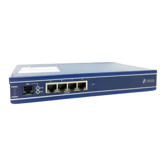
2: GW6600 Series hardware _______________________________________________________________________________________________________ 2 GW6600 Series hardware 2.1 Hardware specification 2.1.1 GW6600 Series router model variants Model ADSL2+ WiFi CDMA Dual ISDN HSPA Modem GW6610 GW6611 GW6612 GW6630 GW6631 GW6632 GW6640 GW6641 GW6642 GW6650 2.2 Hardware features 2.2.1... -
Page 14: Power Supply
Unit size: 225W 158D 37H mm Unit weight: 916g 2.6 Compliance The GW6600 Series routers are compliant and tested to the following standards: Safety EN60950-1: 2006 + A12: 2011 EN55022: 2010 Class B and EN55024: 2010 Environmental ETSI 300 019-1-3 Sinusoidal Vibration and Shock ETSI 300 019-2-3 Random Vibration _______________________________________________________________________________________________________ ©... -
Page 15: Operating Temperature Range
2: GW6600 Series hardware _______________________________________________________________________________________________________ 2.7 Operating temperature range The operating temperature range depends on the router model and the router’s type of module. Region 2G Bands 3G Bands LTE Bands Operating Orde Band Temp Code Europe 850/900/1800/ 900/2100 -40°C to 70°C... -
Page 16: Antenna
-40°C to +70°C PSU 2.8 Antenna GW6600 Series routers have four SMA connectors for connection of up to four antennas for antenna diversity. Antenna diversity helps improve the quality of a wireless link by mitigating problems associated with multipath interference. -
Page 17: Inserting The Sim Cards
1 x lockable SIM cover. 1 x 3G antenna 1 x WiFi antenna Extra antennas Virtual Access supplies a wide range of antennas for 3G and WiFi. Please visit our website: www.virtualaccess.com contact Virtual Access for more information. Table 4: GW6600 Series router optional components 2.10... -
Page 18: Connecting The Wifi Antenna
Over 30 seconds Releasing after 30 seconds performs a normal reset. Table 5: GW6600 Series router reset behaviour 2.16.1 Recovery mode Recovery mode is a fail-safe mode where the router can load a default configuration from the routers firmware. If your router goes into recovery mode, all config files are kept intact. -
Page 19: Gw6600 Series Led Behaviour
_______________________________________________________________________________________________________ 3 GW6600 Series LED behaviour 3.1 Main LED behaviour The GW6600 Series router has single colour LEDs. When the router is powered on, the power LED is green. Figure 1: LEDs on a GW6630 Series router The possible LED states are: •... - Page 20 Flashing Modem training. No data transmit. Dial modem DAT LED Flashing Transmit data. Table 7: Dial modem LED behaviour on GW6600 Series models Applies to the GW6610-LL model. CESoP enabled. Leased Line SYN LED CESoP disabled. Receive data. Leased Line DAT LED No data received.
-
Page 21: Ethernet Port Led Behaviour
3: GW6600 Series LED behaviour _______________________________________________________________________________________________________ 3.2 Ethernet port LED behaviour The Ethernet port has two LEDs: a LINK LED (green) and an ACT LED (amber). When looking at the port, the LED on the left hand side is the LINK LED, and the ACT LED is on the right hand side. -
Page 22: Factory Configuration Extraction From Sim Card
4: Factory configuration extraction from SIM card _______________________________________________________________________________________________________ 4 Factory configuration extraction from SIM card Virtual Access routers have a feature to update the factory configuration from a SIM card. This allows you to change the factory configuration of a router when installing the SIM. -
Page 23: Accessing The Router
The default settings are shown below. The username and password are case sensitive. In the username field, type root. In the Password field, type admin. Click Login. The Status page appears. _______________________________________________________________________________________________________ © Virtual Access 2018 GW6600 Series User manual Issue: 1.7 Page 23 of 519... -
Page 24: Accessing The Router Over Ethernet Using An Ssh Client
SCP server. No dedicated SPC client is supported; select the SCP client software of your own choice. _______________________________________________________________________________________________________ © Virtual Access 2018 GW6600 Series User manual Issue: 1.7 Page 24 of 519... -
Page 25: Accessing The Router Over Ethernet Using A Telnet Client
In the Router Password section, type your new password in the password field and then retype the password in the confirmation field. Scroll down the page and click Save & Apply. Note: the username ‘root’ cannot be changed. _______________________________________________________________________________________________________ © Virtual Access 2018 GW6600 Series User manual Issue: 1.7 Page 25 of 519... -
Page 26: Configuring The Password Using Uci
'$1$wRYYiJOz$EeHN.GQcxXhRgNPVbqxVw option password ‘newpassword’ The new password will take effect after reboot and will now be displayed in encrypted format via the hashpassword option. _______________________________________________________________________________________________________ © Virtual Access 2018 GW6600 Series User manual Issue: 1.7 Page 26 of 519... -
Page 27: Accessing The Device Using Radius Authentication
'radius' option servers '192.168.0.1:3333|test|20 192.168.2.5|secret|10' config 'pam_auth' option enabled 'yes' option pamservice 'luci" option pammodule 'auth' option pamcontrol 'sufficient' option type 'radius' servers '192.168.0.1:3333|test|20 192.168.2.5|secret|10' _______________________________________________________________________________________________________ © Virtual Access 2018 GW6600 Series User manual Issue: 1.7 Page 27 of 519... -
Page 28: Accessing The Device Using Tacacs+ Authentication
TACACS+ authentication can be configured for accessing the router over SSH, web or local console interface. package system config system 'main' option hostname 'VirtualAccess' option timezone 'UTC' config pam_auth option enabled 'yes' option pamservice 'sshd' _______________________________________________________________________________________________________ © Virtual Access 2018 GW6600 Series User manual Issue: 1.7 Page 28 of 519... - Page 29 'sufficient' option type 'tacplus' option servers '192.168.0.1:49|secret' config pam_auth option enabled 'yes' option pamservice 'luci' option pammodule 'account' option pamcontrol 'sufficient' option type 'tacplus' _______________________________________________________________________________________________________ © Virtual Access 2018 GW6600 Series User manual Issue: 1.7 Page 29 of 519...
- Page 30 'service=ppp' config pam_auth option enabled 'yes' option pamservice 'login' option pammodule 'session' option pamcontrol 'sufficient' option type 'tacplus' option servers '192.168.0.1:49|secret' option args 'service=ppp' _______________________________________________________________________________________________________ © Virtual Access 2018 GW6600 Series User manual Issue: 1.7 Page 30 of 519...
-
Page 31: Ssh
SSH allows you to access remote machines over text-based shell sessions. SSH uses public key cryptography to create a secure connection. These connections allow you to issue commands remotely via a command line. _______________________________________________________________________________________________________ © Virtual Access 2018 GW6600 Series User manual Issue: 1.7 Page 31 of 519... - Page 32 In the top menu, click System -> Administration. The Administration page appears. Scroll down to the SSH Access section. Figure 7: The SSH access section _______________________________________________________________________________________________________ © Virtual Access 2018 GW6600 Series User manual Issue: 1.7 Page 32 of 519...
-
Page 33: Package Dropbear Using Uci
Table 13: Information table for SSH access settings 5.12 Package dropbear using UCI root@VA_router:~# uci show dropbear dropbear.@dropbear[0]=dropbear dropbear.@dropbear[0].PasswordAuth=on dropbear.@dropbear[0].RootPasswordAuth=on dropbear.@dropbear[0].GatewayPorts=0 dropbear.@dropbear[0].IdleTimeout=30 dropbear.@dropbear[0].Port=22 dropbear.@dropbear[0].MaxLoginAttempts=3 Package dropbear using package options _______________________________________________________________________________________________________ © Virtual Access 2018 GW6600 Series User manual Issue: 1.7 Page 33 of 519... -
Page 34: Certs And Private Keys
There is support for IPSec, OpenVPN and VA certificates and keys. If you have generated your own SSH public keys, you can input them in the SSH Keys section, for SSH public key authentication. _______________________________________________________________________________________________________ © Virtual Access 2018 GW6600 Series User manual Issue: 1.7 Page 34 of 519... -
Page 35: Configuring A Router's Web Server
To configure the router’s HTTP server parameters, in the top menu, select Services -> HTTP Server. The HTTP Server page has two sections. Main Settings Server configurations Certificate Settings SSL certificates. _______________________________________________________________________________________________________ © Virtual Access 2018 GW6600 Series User manual Issue: 1.7 Page 35 of 519... - Page 36 ASN.1/DER private key used to serve HTTPS connections. If no listen_https options are given the key options are ignored. UCI: uhttpd.main.key /etc/uhttpd.key Opt: key Range _______________________________________________________________________________________________________ © Virtual Access 2018 GW6600 Series User manual Issue: 1.7 Page 36 of 519...
- Page 37 Does not follow symbolic links if enabled. UCI: uhttpd.main.no_symlinks Disabled. Opt: no_symlinks Enabled. Web: N/A Does not generate directory listings if enabled. UCI: uhttpd.main.no_dirlists Disabled. Opt: no_symlinks Enabled. _______________________________________________________________________________________________________ © Virtual Access 2018 GW6600 Series User manual Issue: 1.7 Page 37 of 519...
- Page 38 '0.0.0.0:443' option home '/www' option rfc1918_filter '1' option cert '/etc/uhttpd.crt' option key '/etc/uhttpd.key' option cgi_prefix '/cgi-bin' option script_timeout '60' option network_timeout '30' option config '/etc/http.conf' _______________________________________________________________________________________________________ © Virtual Access 2018 GW6600 Series User manual Issue: 1.7 Page 38 of 519...
- Page 39 Activation, this must be set to the serial number (Eth0 UCI: uhttpd.commonname MAC address) of the device. Opt: commonname Table 15: Information table for HTTP server certificate settings _______________________________________________________________________________________________________ © Virtual Access 2018 GW6600 Series User manual Issue: 1.7 Page 39 of 519...
-
Page 40: Basic Authentication (Httpd Conf)
/etc/shadow or /etc/passwd. If you use $p$… format, uhttpd will compare the client provided password against the one stored in the shadow or passwd database. _______________________________________________________________________________________________________ © Virtual Access 2018 GW6600 Series User manual Issue: 1.7 Page 40 of 519... -
Page 41: Securing Uhttpd
The following example shows how to display serial number and mobile signal strength. Note: this can only be configured via the command line. Figure 12: Example login screen displaying serial and signal strength _______________________________________________________________________________________________________ © Virtual Access 2018 GW6600 Series User manual Issue: 1.7 Page 41 of 519... - Page 42 'local hue = (sig + 113) * 2' list text 'local hue = math.min(math.max(hue, 0), 120) %>' list text 'Signal strength: <h3 style="color:hsl(<%=hue%>, 90%, 50%); display:inline;"><%=sig%></h3> dBm _______________________________________________________________________________________________________ © Virtual Access 2018 GW6600 Series User manual Issue: 1.7 Page 42 of 519...
-
Page 43: Router File Structure
Figure 13: Example of the status page System information is also available from the CLI if you enter the following command: root@VA_router:~# va_vars.sh _______________________________________________________________________________________________________ © Virtual Access 2018 GW6600 Series User manual Issue: 1.7 Page 43 of 519... -
Page 44: Identify Your Software Version
In the Firmware Version row, the first two digits of the firmware version identify the hardware platform, for example LIS-15; while the remaining digits: .00.72.002, show the software version. _______________________________________________________________________________________________________ © Virtual Access 2018 GW6600 Series User manual Issue: 1.7 Page 44 of 519... -
Page 45: Image Files
To show the configuration to run after the next reboot, enter: root@VA_router:~# va_config.sh next To set the configuration to run after the next reboot, enter: root@VA_router:~# va_config.sh -s [factconf|config1|config2|altconfig] _______________________________________________________________________________________________________ © Virtual Access 2018 GW6600 Series User manual Issue: 1.7 Page 45 of 519... -
Page 46: Configuration File Syntax
Configurations can also be managed using directory manipulation. To remove the contents of the current folder, enter: root@VA_router:/etc/config1# rm –f * Warning: the above command makes irreversible changes. _______________________________________________________________________________________________________ © Virtual Access 2018 GW6600 Series User manual Issue: 1.7 Page 46 of 519... -
Page 47: Exporting A Configuration File
In the top menu, select System > Backup/Flash Firmware. The Flash operations page appears. Figure 16: The flash operations page In the Backup/Restore section, select Generate Archive. _______________________________________________________________________________________________________ © Virtual Access 2018 GW6600 Series User manual Issue: 1.7 Page 47 of 519... -
Page 48: Importing A Configuration File
6.9.1. If you have software version 72.002 or above, export a configuration file using the web interface go to section 6.9.2. _______________________________________________________________________________________________________ © Virtual Access 2018 GW6600 Series User manual Issue: 1.7 Page 48 of 519... - Page 49 Upload archive. Figure 19: The system – restoring…page When the ‘waiting for router’ icon disappears, the upgrade is complete, and the login homepage appears. _______________________________________________________________________________________________________ © Virtual Access 2018 GW6600 Series User manual Issue: 1.7 Page 49 of 519...
- Page 50 OK to return to the Flash Operations page. There you can manually select Made Active (after reboot). Then click Reboot Now in the ‘Reboot using Active Configuration’ section. _______________________________________________________________________________________________________ © Virtual Access 2018 GW6600 Series User manual Issue: 1.7 Page 50 of 519...
- Page 51 <paste in config file> <CTRL-D> Note: it is very important that the config file is in the correct format otherwise it will not import correctly. _______________________________________________________________________________________________________ © Virtual Access 2018 GW6600 Series User manual Issue: 1.7 Page 51 of 519...
-
Page 52: Using The Command Line Interface
_______________________________________________________________________________________________________ 7 Using the Command Line Interface This chapter explains how to view Virtual Access routers' log files and edit configuration files using a Command Line Interface (CLI) and the Unified Configuration Interface (UCI) system. Some commands may vary between router models. - Page 53 0 Jul 3 11:37 usr lrwxrwxrwx 1 root root 4 Jul 16 2012 var -> /tmp drwxr-xr-x 4 root root 67 Jul 16 2012 www _______________________________________________________________________________________________________ © Virtual Access 2018 GW6600 Series User manual Issue: 1.7 Page 53 of 519...
- Page 54 444 S -ash 374 root 344 R ps ax 375 root 400 S /bin/sh /sbin/hotplug button 384 root 396 R /bin/sh /sbin/hotplug button 385 root [keventd] _______________________________________________________________________________________________________ © Virtual Access 2018 GW6600 Series User manual Issue: 1.7 Page 54 of 519...
-
Page 55: Using Unified Configuration Interface (Uci)
-f <file> use <file> as input instead of stdin when importing, merge data into an existing package _______________________________________________________________________________________________________ © Virtual Access 2018 GW6600 Series User manual Issue: 1.7 Page 55 of 519... - Page 56 Note: all operations do not act directly on the configuration files. A commit command is required after you have finished your configuration. root@VA_router:~# uci commit _______________________________________________________________________________________________________ © Virtual Access 2018 GW6600 Series User manual Issue: 1.7 Page 56 of 519...
- Page 57 To show the configuration ‘tree’ for a given config, enter: root@VA_router:/# uci show network network.loopback=interface network.loopback.ifname=lo network.loopback.proto=static network.loopback.ipaddr=127.0.0.1 network.loopback.netmask=255.0.0.0 network.lan=interface network.lan.ifname=eth0 network.lan.proto=dhcp network.wan=interface network.wan.username=foo _______________________________________________________________________________________________________ © Virtual Access 2018 GW6600 Series User manual Issue: 1.7 Page 57 of 519...
- Page 58 To show the image running currently, enter: root@VA_router:~# vacmd show current image To set the image to run on next reboot, enter: root@VA_router:~# vacmd set next image [image1|image2|altimage] root@VA_router:~# reboot _______________________________________________________________________________________________________ © Virtual Access 2018 GW6600 Series User manual Issue: 1.7 Page 58 of 519...
- Page 59 _______________________________________________________________________________________________________ © Virtual Access 2018 GW6600 Series User manual Issue: 1.7 Page 59 of 519...
-
Page 60: Configuration Files
7.3 Configuration files The table below lists common package configuration files that can be edited using uci commands. Other configuration files may also be present depending on the specific options available on the Virtual Access router. File Description Management... - Page 61 It is important to note that identifiers and config file names may only contain the characters a-z, A-Z, 0-9 and _. However, option values may contain any character, as long they are properly quoted. _______________________________________________________________________________________________________ © Virtual Access 2018 GW6600 Series User manual Issue: 1.7 Page 61 of 519...
-
Page 62: Upgrading Router Firmware
To check which software version your router is running, in the top menu, browse to Status -> Overview. Figure 22: The status page showing a software version prior to 72.002 _______________________________________________________________________________________________________ © Virtual Access 2018 GW6600 Series User manual Issue: 1.7 Page 62 of 519... - Page 63 8.1.2 Upgrading router firmware for software versions pre- 72.002 Copy the new firmware issued by Virtual Access to a PC connected to the router. In the top menu, select System tab -> Backup/Flash Firmware. The Flash operations page appears.
- Page 64 To verify that the router has been upgraded successfully, click Status in the top menu. The Firmware Version shows in the system list. Figure 27: The system status list _______________________________________________________________________________________________________ © Virtual Access 2018 GW6600 Series User manual Issue: 1.7 Page 64 of 519...
- Page 65 8.1.3 Upgrading router firmware for software version 72.002 and above Copy the new firmware issued by Virtual Access to a PC connected to the router. In the top menu, select System tab > Flash operations. The Flash operations page appears.
- Page 66 To regain access to the router you must login again. If any part of the processes encounters an error the reboot does not occur and a report is given. _______________________________________________________________________________________________________ © Virtual Access 2018 GW6600 Series User manual Issue: 1.7 Page 66 of 519...
- Page 67 Version shows in the system list and also in the right top corner of the menu bar. Figure 33: The system status list showing current firmware version _______________________________________________________________________________________________________ © Virtual Access 2018 GW6600 Series User manual Issue: 1.7 Page 67 of 519...
-
Page 68: Upgrading Firmware Using Cli
Windows it requires an additional application. The usage example below is for a Unix machine and therefore assumes the image file is in the current folder. scp LIS-15.00.72.002.image root@x.x.x.x:/tmp/LIS-15.00.72.002.image _______________________________________________________________________________________________________ © Virtual Access 2018 GW6600 Series User manual Issue: 1.7 Page 68 of 519... - Page 69 After the write process has finished, you must complete a post verification of the firmware. To verify the checksum of downloaded firmware, enter: va_image_csum.sh /tmp/LIS-15.00.72.002.image _______________________________________________________________________________________________________ © Virtual Access 2018 GW6600 Series User manual Issue: 1.7 Page 69 of 519...
-
Page 70: Firmware Recovery
Change the boot configuration to factory configuration after ten failed restarts • By design this feature is intended to allow recovery from firmware problems and therefore excludes restarts due to power loss. _______________________________________________________________________________________________________ © Virtual Access 2018 GW6600 Series User manual Issue: 1.7 Page 70 of 519... -
Page 71: System Settings
A filter matches specific log messages and then determines an action for them. 9.2 Configuration package used Package Sections system main syslog_fillter timeserver _______________________________________________________________________________________________________ © Virtual Access 2018 GW6600 Series User manual Issue: 1.7 Page 71 of 519... -
Page 72: Configuring System Properties
Defines the interval in minutes to store the local time for use on next reboot. UCI: system.main.timezone Opt: time_save_interval_min Table 17: Information table for general settings section _______________________________________________________________________________________________________ © Virtual Access 2018 GW6600 Series User manual Issue: 1.7 Page 72 of 519... - Page 73 External syslog server IP address. If defined syslog messages will be sent in addition to local storage. UCI: system.main.log_ip Range IP of FQDN Opt: log_ip 0.0.0.0 _______________________________________________________________________________________________________ © Virtual Access 2018 GW6600 Series User manual Issue: 1.7 Page 73 of 519...
- Page 74 May indicate that an error will occur if action is not taken. Error Error conditions Critical Critical conditions Alert Should be addressed immediately Emergency System is unusable _______________________________________________________________________________________________________ © Virtual Access 2018 GW6600 Series User manual Issue: 1.7 Page 74 of 519...
- Page 75 1024 6 hours Table 18: Information table for the logging section 9.3.3 Language and style Figure 36: The language and style section in system properties _______________________________________________________________________________________________________ © Virtual Access 2018 GW6600 Series User manual Issue: 1.7 Page 75 of 519...
- Page 76 NTP Server will derive the stratum from the NTP dialogue. Blank NTP server will derive stratum Range Table 20: Information table for time synchronization section _______________________________________________________________________________________________________ © Virtual Access 2018 GW6600 Series User manual Issue: 1.7 Page 76 of 519...
-
Page 77: System Settings Using Command Line
Advanced filter rules (see Advanced filter section) 9.4.1 System settings using UCI root@VA_router:~# uci show system system.main=system system.main.hostname=VA_router system.main.timezone=UTC system.main.log_ip=1.1.1.1 system.main.log_port=514 system.main.remoteloglevel=8 system.main.log_file=/root/syslog.messages system.main.log_size=400 system.main.log_type=file _______________________________________________________________________________________________________ © Virtual Access 2018 GW6600 Series User manual Issue: 1.7 Page 77 of 519... - Page 78 "10" option conloglevel '8' option cronloglevel '8' config 'timeserver' 'ntp' option interval_hours 'auto' list server "0.VA_router.pool.ntp.org" list server ’10.10.10.10’ option listen ‘LAN1 LAN2’ _______________________________________________________________________________________________________ © Virtual Access 2018 GW6600 Series User manual Issue: 1.7 Page 78 of 519...
-
Page 79: System Diagnostics
To view the system log in RAM, enter: root@VA_router:~# logread Shows the log. root@VA_router:~# logread |tail Shows end of the log. root@VA_router:~# logread | more Shows the log page by page. _______________________________________________________________________________________________________ © Virtual Access 2018 GW6600 Series User manual Issue: 1.7 Page 79 of 519... - Page 80 /etc/init.d/syslogd restart root@VA_router:~# cat /root/syslog.messages Shows all the system events stored in flash. root@VA_router:~# tail /root/syslog.messages Shows end of the events stored flash. _______________________________________________________________________________________________________ © Virtual Access 2018 GW6600 Series User manual Issue: 1.7 Page 80 of 519...
- Page 81 0.000000] SoC: xRX330 rev 1.1 0.000000] bootconsole [early0] enabled 0.000000] CPU0 revision is: 00019556 (MIPS 34Kc) 0.000000] adding memory size:267386880 from DT 0.000000] MIPS: machine is Virtual Access GW6600V series 0.000000] Determined physical RAM map: 0.000000] memory: 0ff00000 @ 00000000 (usable) 0.000000] User-defined physical RAM map:...
-
Page 82: Advanced Filtering Of Syslog Messages
Filters are defined in the syslog_filter configuration section of the system package. A set of filters can be either local or remote. All messages are matched against both local and remote filter rules, if configured. • _______________________________________________________________________________________________________ © Virtual Access 2018 GW6600 Series User manual Issue: 1.7 Page 82 of 519... - Page 83 Use the wildcard '*' to match all facilities. _______________________________________________________________________________________________________ © Virtual Access 2018 GW6600 Series User manual Issue: 1.7 Page 83 of 519...
- Page 84 Log all ipsec messages to filepath ‘va/log/ipsec’. Do not log anywhere else locally. For everything else, apply default local logging. No remote filter rules defined, so apply default remote logging to all messages. config syslog_filter 'local' _______________________________________________________________________________________________________ © Virtual Access 2018 GW6600 Series User manual Issue: 1.7 Page 84 of 519...
- Page 85 '*.* default' config syslog_filter 'remote' list text 'auth,authpriv.* ~' list text '*.* ignore' 9.6.4 Filter diagnostics To view configured filters, enter cat /var/conf/syslog.conf _______________________________________________________________________________________________________ © Virtual Access 2018 GW6600 Series User manual Issue: 1.7 Page 85 of 519...
- Page 86 9: System settings _______________________________________________________________________________________________________ root@VA_router:~# cat /var/conf/syslog.conf [local] auth,authpriv.* /var/log/auth *.*(ipsec:) /var/log/ipsec default [remote] auth,authpriv.info *.* ignore _______________________________________________________________________________________________________ © Virtual Access 2018 GW6600 Series User manual Issue: 1.7 Page 86 of 519...
-
Page 87: Configuring An Ethernet Interface
To create and edit interfaces via the web interface, in the top menu, click Network -> Interfaces. The Interfaces overview page appears. Figure 39: The interfaces overview page _______________________________________________________________________________________________________ © Virtual Access 2018 GW6600 Series User manual Issue: 1.7 Page 87 of 519... - Page 88 To create a new interface, in the Interface Overview section, click Add new interface. The Create Interface page appears. Figure 40: The create interface page _______________________________________________________________________________________________________ © Virtual Access 2018 GW6600 Series User manual Issue: 1.7 Page 88 of 519...
- Page 89 Configure the interface settings such as protocol, IP address, gateway, netmask, custom DNS servers, MTU and firewall configuration. IP-Aliases Assigning multiple IP addresses to the interface. DHCP Server Configuring DHCP server settings for this interface. _______________________________________________________________________________________________________ © Virtual Access 2018 GW6600 Series User manual Issue: 1.7 Page 89 of 519...
- Page 90 Bridge interfaces, VLAN PCP to SKB priority mapping. Firewall settings Assign a firewall zone to the interface. 10.2.3.1 Common configuration – general setup Figure 41: The Ethernet connection common configuration settings page _______________________________________________________________________________________________________ © Virtual Access 2018 GW6600 Series User manual Issue: 1.7 Page 90 of 519...
- Page 91 The IPv6 IP address of the interface. Optional if an IPv4 address is provided. UCI: network.<if name>.ip6addr CIDR notation for the IPv6 address is required. Opt: ip6addr _______________________________________________________________________________________________________ © Virtual Access 2018 GW6600 Series User manual Issue: 1.7 Page 91 of 519...
- Page 92 UCI: network.<if name>.macaddr Opt: macaddr Web: Override MTU Defines the value to override the default MTU on this interface. UCI: network.<if name>.mtu 1500 1500 bytes Opt: mtu _______________________________________________________________________________________________________ © Virtual Access 2018 GW6600 Series User manual Issue: 1.7 Page 92 of 519...
- Page 93 0 - 4294966295 Table 26: Information table for common configuration advanced settings 10.2.3.3 Common configuration: physical settings Figure 43: The common configuration physical settings page _______________________________________________________________________________________________________ © Virtual Access 2018 GW6600 Series User manual Issue: 1.7 Page 93 of 519...
- Page 94 Select unspecified to remove the interface from the associated zone or fill out the create field to define a new zone and attach the interface to it. _______________________________________________________________________________________________________ © Virtual Access 2018 GW6600 Series User manual Issue: 1.7 Page 94 of 519...
- Page 95 To use IP-aliases, enter a name for the alias and click Add. This name will be assigned to the alias section for this IP-alias. In this example, we use the name ‘ethalias1’. Figure 45: The IP-Aliases section _______________________________________________________________________________________________________ © Virtual Access 2018 GW6600 Series User manual Issue: 1.7 Page 95 of 519...
- Page 96 Opt: netmask Web: IPv4-Gateway Defines the gateway for the IP alias. UCI: network.<alias name>.gateway Opt: gateway Table 29: Information table for IP-Alias general setup page _______________________________________________________________________________________________________ © Virtual Access 2018 GW6600 Series User manual Issue: 1.7 Page 96 of 519...
- Page 97 Figure 48: The DHCP Server settings section The DHCP Server configuration options will appear. The DHCP Server is divided into two sub sections – general setup and advanced. _______________________________________________________________________________________________________ © Virtual Access 2018 GW6600 Series User manual Issue: 1.7 Page 97 of 519...
- Page 98 Defines the size of the address pool. UCI: dhcp.@dhcp[x].limit Example: for network address 192.168.100.10/24, start=100, limit=150, DHCP allocation pool will be .100 to .249 Opt: limit Range 0 – 255 _______________________________________________________________________________________________________ © Virtual Access 2018 GW6600 Series User manual Issue: 1.7 Page 98 of 519...
- Page 99 Range Table 32: Information table for DHCP advanced settings page For more advanced configuration on the DHCP server, read ‘DHCP server and DNS configuration section. _______________________________________________________________________________________________________ © Virtual Access 2018 GW6600 Series User manual Issue: 1.7 Page 99 of 519...
-
Page 100: Interface Configuration Using Command Line
….. firewall.@zone[0]=zone firewall.@zone[0].name=lan firewall.@zone[0].input=ACCEPT firewall.@zone[0].output=ACCEPT firewall.@zone[0].forward=ACCEPT firewall.@zone[0].network=lan newinterface root@VA_router:~# uci show dhcp … _______________________________________________________________________________________________________ © Virtual Access 2018 GW6600 Series User manual Issue: 1.7 Page 100 of 519... - Page 101 '10.10.10.1' option netmask '255.255.255.0' option gateway '10.10.10.10' option bcast '10.10.10.255' option dns '8.8.8.8' root@VA_router:~# uci export firewall package firewall config zone option name 'lan' _______________________________________________________________________________________________________ © Virtual Access 2018 GW6600 Series User manual Issue: 1.7 Page 101 of 519...
- Page 102 An example showing a partial uci export of a loopback interface configuration is shown below. root@VA_router:~# uci export network ….. config interface 'loopback' option proto 'static' option ifname 'lo' option ipaddr '127.0.0.1' option netmask '255.0.0.0' _______________________________________________________________________________________________________ © Virtual Access 2018 GW6600 Series User manual Issue: 1.7 Page 102 of 519...
-
Page 103: Configuring Port Maps
Eth3 assigned to switch port B Eth3 assigned to switch port C Eth3 assigned to switch port C Table 33: Information table for interface port map page _______________________________________________________________________________________________________ © Virtual Access 2018 GW6600 Series User manual Issue: 1.7 Page 103 of 519... -
Page 104: Interface Diagnostics
P-t-P:178.72.0.237 Mask:255.255.255.255 UP POINTOPOINT RUNNING NOARP MULTICAST MTU:1400 Metric:1 RX packets:6 errors:0 dropped:0 overruns:0 frame:0 TX packets:23 errors:0 dropped:0 overruns:0 carrier:0 collisions:0 txqueuelen:3 _______________________________________________________________________________________________________ © Virtual Access 2018 GW6600 Series User manual Issue: 1.7 Page 104 of 519... - Page 105 UP BROADCAST RUNNING MULTICAST MTU:1500 Metric:1 RX packets:7710 errors:0 dropped:0 overruns:0 frame:0 TX packets:535 errors:0 dropped:0 overruns:0 carrier:0 collisions:0 txqueuelen:1000 RX bytes:647933 (632.7 KiB) TX bytes:80978 (79.0 KiB) _______________________________________________________________________________________________________ © Virtual Access 2018 GW6600 Series User manual Issue: 1.7 Page 105 of 519...
- Page 106 Flags Metric Ref Use Iface 192.168.100.0 255.255.255.0 0 eth0 Note: a route will only be displayed in the routing table when the interface is up. _______________________________________________________________________________________________________ © Virtual Access 2018 GW6600 Series User manual Issue: 1.7 Page 106 of 519...
-
Page 107: Configuring Vlan
11: Configuring VLAN _______________________________________________________________________________________________________ 11 Configuring VLAN 11.1 Maximum number of VLANs supported Virtual Access’ routers support up to 4095 VLANs. 11.2 Configuration package used Package Sections Network 11.3 Configuring VLAN using the web interface 11.3.1 Create a VLAN interface To configure VLAN using the web interface, in the top menu, select Network - >Interfaces. - Page 108 Enter a name, for example eth0.100. This will assign VLAN 100 to the eth0 interface. Opt: ifname Table 34: Information table for the create interface page Click Submit. The Interfaces page for VLAN1 appears. _______________________________________________________________________________________________________ © Virtual Access 2018 GW6600 Series User manual Issue: 1.7 Page 108 of 519...
- Page 109 The IPv4 address of the interface. This is optional if an IPv6 address is provided. UCI: network.VLAN1.ipaddr Opt: ipaddr Web: IPv4 netmask Subnet mask to be applied to the IP address of this interface. UCI: network.VLAN1.netmask Opt: netmask _______________________________________________________________________________________________________ © Virtual Access 2018 GW6600 Series User manual Issue: 1.7 Page 109 of 519...
-
Page 110: Viewing Vlan Interface Settings
To view the new VLAN interface settings, in the top menu, select Network -> Interfaces. The Interfaces Overview page appears. The example below shows two VLAN interfaces configured. _______________________________________________________________________________________________________ © Virtual Access 2018 GW6600 Series User manual Issue: 1.7 Page 110 of 519... -
Page 111: Configuring Vlan Using The Uci Interface
When specifying the ifname ensure that it is written in dotted mode, that is, eth1.100 where eth1 is the physical interface assigned to VLAN tag 100. Note: VLAN1 is, by default the native VLAN and will not be tagged. _______________________________________________________________________________________________________ © Virtual Access 2018 GW6600 Series User manual Issue: 1.7 Page 111 of 519... -
Page 112: Configuring A Wifi Connection
_______________________________________________________________________________________________________ 12 Configuring a WiFi connection This section explains how to configure WiFi on a Virtual Access router using the web interface or via UCI. WiFi can act as an Access Point (AP) to another device in the network or it can act as a client to an existing AP. - Page 113 Web: Transmit power Select the transmit power range range you require. UCI: wireless.radio0.txpower Range 0dBm(1mW)-17dBm(50mW) Opt: txpower 17dBM(50mW) Table 36: Information table for the device configuration section _______________________________________________________________________________________________________ © Virtual Access 2018 GW6600 Series User manual Issue: 1.7 Page 113 of 519...
- Page 114 Web: RTS/CTS Threshold Defines the RTS/CTS threshold. UCI: wireless.radio0.rts None Router defaults applied Opt: rts Range Table 37: Information table for device configuration advanced settings _______________________________________________________________________________________________________ © Virtual Access 2018 GW6600 Series User manual Issue: 1.7 Page 114 of 519...
- Page 115 Use this section to configure the interface name, mode and network settings. Differing web options may be presented depending on the mode selected. Figure 59: The interface configuration general setup section _______________________________________________________________________________________________________ © Virtual Access 2018 GW6600 Series User manual Issue: 1.7 Page 115 of 519...
- Page 116 Use this section to configure encryption, ciper and create a security key. Differing options will be defined depending on the encryption selected. Figure 60: The wireless security section _______________________________________________________________________________________________________ © Virtual Access 2018 GW6600 Series User manual Issue: 1.7 Page 116 of 519...
- Page 117 Web: Radius Accounting -Port Defines the Radius port for EAP accounting. UCI:wireless.@wifi-iface[0].acct_port Opt: acc_port Web: Radius Accounting -Secret Defines the Radius secret for EAP accounting. UCI:wireless.@wifi-iface[0].acct_secret Opt: acct_secret _______________________________________________________________________________________________________ © Virtual Access 2018 GW6600 Series User manual Issue: 1.7 Page 117 of 519...
-
Page 118: Configuring Wifi In Ap Mode
WiFi interface’, selecting a new interface for the Wireless Network in the Interface Configuration section. Next, in the top menu, select Network -> Interfaces. The Interface Overview page appears. _______________________________________________________________________________________________________ © Virtual Access 2018 GW6600 Series User manual Issue: 1.7 Page 118 of 519... - Page 119 UCI and package options. Opt:ifname Example: option ifname ‘eth2 eth3’ or network.<if name>.ifname=eth2 eth 3 Table 41: Information table for the physical section on the common configuration page _______________________________________________________________________________________________________ © Virtual Access 2018 GW6600 Series User manual Issue: 1.7 Page 119 of 519...
-
Page 120: Configuring Wifi Using Uci
'US' config wifi-iface option device 'radio0' option mode 'ap' option disabled '1' option ssid 'Test_AP' option network 'newwifilan' option encryption 'psk' option key 'secretkey' _______________________________________________________________________________________________________ © Virtual Access 2018 GW6600 Series User manual Issue: 1.7 Page 120 of 519... - Page 121 'lan' option ifname 'eth0' option proto 'static' option ipaddr '192.168.100.1' option netmask '255.255.255.0' option type 'bridge' root@VA_router:~# uci export wireless package wireless _______________________________________________________________________________________________________ © Virtual Access 2018 GW6600 Series User manual Issue: 1.7 Page 121 of 519...
- Page 122 12.4.4 AP mode on an existing Ethernet interface using UCI root@VA_router:~# uci show network network.lan=interface network.lan.ifname=eth0 network.lan.proto=static network.lan.ipaddr=192.168.6.1 network.lan.netmask=255.255.255.0 network.lan.type=bridge root@VA_router:~# uci show wireless wireless.radio0=wifi-device wireless.radio0.type=mac80211 wireless.radio0.channel=11 wireless.radio0.phy=phy0 wireless.radio0.hwmode=11ng _______________________________________________________________________________________________________ © Virtual Access 2018 GW6600 Series User manual Issue: 1.7 Page 122 of 519...
-
Page 123: Creating A Wifi In Client Mode Using The Web Interface
In the top menu, select Network -> Interfaces. The Interfaces Overview page appears. Click Edit in the newly created WiFi Client interface. The Common Configuration page appears. Figure 63: The client interface page _______________________________________________________________________________________________________ © Virtual Access 2018 GW6600 Series User manual Issue: 1.7 Page 123 of 519... -
Page 124: Configuring Wifi In Client Mode Using Command Line
'radio0' option type 'mac80211' option channel '11' option phy 'phy0' option hwmode '11ng' option htmode 'HT20' list ht_capab 'SHORT-GI-40' _______________________________________________________________________________________________________ © Virtual Access 2018 GW6600 Series User manual Issue: 1.7 Page 124 of 519... - Page 125 12.6.2.1 uci show wireless root@VA_router:~# uci show wireless wireless.radio0=wifi-device wireless.radio0.type=mac80211 wireless.radio0.channel=11 wireless.radio0.phy=phy0 wireless.radio0.hwmode=11ng wireless.radio0.htmode=HT20 wireless.radio0.ht_capab=SHORT-GI-40 TX-STBC RX-STBC1 DSSS_CCK-40 wireless.radio0.txpower=17 wireless.radio0.country=US wireless.@wifi-iface[0]=wifi-iface wireless.@wifi-iface[0].device=radio0 wireless.@wifi-iface[0].ssid=Remote-AP wireless.@wifi-iface[0].mode=sta wireless.@wifi-iface[0].network= newwifiClient wireless.@wifi-iface[0].encryption=psk2 wireless.@wifi-iface[0].key=testtest _______________________________________________________________________________________________________ © Virtual Access 2018 GW6600 Series User manual Issue: 1.7 Page 125 of 519...
-
Page 126: Configuring An Adsl Interface
If you select the routed PPP service, you can run the PPP over ATM (PPPoA) or over Ethernet (PPPOE). The following diagrams illustrate the topology of these connections. Figure 64: A routed ADSL connection over PPPoA _______________________________________________________________________________________________________ © Virtual Access 2018 GW6600 Series User manual Issue: 1.7 Page 126 of 519... -
Page 127: Configuration Package Used
DHCP or PPP to dial into the provider network. In the Interface Overview section, click Add new interface. The Create Interface page appears. _______________________________________________________________________________________________________ © Virtual Access 2018 GW6600 Series User manual Issue: 1.7 Page 127 of 519... - Page 128 Opt: type Web: Cover the following interface Select interfaces for bridge connection. UCI: network.[..x..].ifname Opt:ifname Table 43: Information table for the create new interface page _______________________________________________________________________________________________________ © Virtual Access 2018 GW6600 Series User manual Issue: 1.7 Page 128 of 519...
-
Page 129: Pppoa: General Setup
Web: ATM Device Number UCI: network.[..x..]. atmdev Opt:atmdev Web: ATM Virtual Channel Identifier (VCi) UCI: network.[..x..].vci Range Opt:vci Web: ATM Virtual Path Identifier (VPi) UCI: network.[..xx..].vpi Range Opt:vpi _______________________________________________________________________________________________________ © Virtual Access 2018 GW6600 Series User manual Issue: 1.7 Page 129 of 519... -
Page 130: Pppoa: Advanced Settings
Defines the route metric for this default route. Lower metrics take priority. Option only shown when ‘Use default gateway’ is enabled. UCI: network.[..x..].metric Opt: metric Range _______________________________________________________________________________________________________ © Virtual Access 2018 GW6600 Series User manual Issue: 1.7 Page 130 of 519... -
Page 131: Pppoa: Firewall Settings
_______________________________________________________________________________________________________ © Virtual Access 2018 GW6600 Series User manual Issue: 1.7 Page 131 of 519... -
Page 132: Creating An Adsl Pppoa Connection Using Uci
'ADSL' option proto 'pppoa' option encaps 'vc' option atmdev '0' option vci '35' option vpi '0' option username 'test5@pppoa.com' option password 'test5' option metric ‘1’ _______________________________________________________________________________________________________ © Virtual Access 2018 GW6600 Series User manual Issue: 1.7 Page 132 of 519... -
Page 133: Creating A New Adsl Pppoeoa Connection
Scroll down to the bottom of the page until you see the ATM Bridges section. Click Add. 13.9.1 PPPoEoA: general setup Figure 70: The ATM bridges general setup page _______________________________________________________________________________________________________ © Virtual Access 2018 GW6600 Series User manual Issue: 1.7 Page 133 of 519... - Page 134 Select Routed to run the PPP over ATM (PPPoA) or over Ethernet (PPPoE). Table 48: Information table for the ATM bridges advanced settings page Click Save. _______________________________________________________________________________________________________ © Virtual Access 2018 GW6600 Series User manual Issue: 1.7 Page 134 of 519...
- Page 135 Select Custom Interface, and then type nas0. UCI: network.[..x..].ifname Opt: ifname Table 49: Information table for create a new interface section Click Submit. The Interfaces page appears. _______________________________________________________________________________________________________ © Virtual Access 2018 GW6600 Series User manual Issue: 1.7 Page 135 of 519...
- Page 136 Leave this field empty to autodetect, or type the Service name. Web: Service name UCI: network.[..x..].service Opt: service Table 50: Information table for the new PPPoEoA interface _______________________________________________________________________________________________________ © Virtual Access 2018 GW6600 Series User manual Issue: 1.7 Page 136 of 519...
- Page 137 Web: LCP echo internal Sends LCP echo requests at the given interval in seconds, only effective in conjunction with failure threshold. UCI: network.[..x..].keepalive Range Opt: keepalive _______________________________________________________________________________________________________ © Virtual Access 2018 GW6600 Series User manual Issue: 1.7 Page 137 of 519...
- Page 138 Click Save & Apply. Figure 75: The interfaces page firewall settings tab _______________________________________________________________________________________________________ © Virtual Access 2018 GW6600 Series User manual Issue: 1.7 Page 138 of 519...
-
Page 139: Configuring An Adsl Pppoeoa Connection Using Uci
'llc' option payload 'bridged' option vci '35' option vpi '0' To view uci commands, enter: uci show network network.adsl=adsl-device network.adsl.fwannex=a network.adsl.annex=a network.adsl.Enabled=yes network.ADSL=interface network.ADSL.proto=pppoe network.ADSL.ifname=nas0 _______________________________________________________________________________________________________ © Virtual Access 2018 GW6600 Series User manual Issue: 1.7 Page 139 of 519... -
Page 140: Configuring An Adsl Bridge Connection With Static Ip
Scroll down to the bottom of the page until you see the ATM Bridges section. Click Add. The ATM Bridges page appears. Figure 76: The ATM bridges section _______________________________________________________________________________________________________ © Virtual Access 2018 GW6600 Series User manual Issue: 1.7 Page 140 of 519... - Page 141 Routed allows the router to run PPP over ATM (PPPoA) or over Ethernet (PPPoE). Table 53: Information table for the ATM bridges advanced settings page Click Save. _______________________________________________________________________________________________________ © Virtual Access 2018 GW6600 Series User manual Issue: 1.7 Page 141 of 519...
- Page 142 Select interfaces for bridge connection. UCI: network.[..x..].ifname Select Custom Interface and then type nas0. Opt: ifname Table 54: Information table for creating a static interface _______________________________________________________________________________________________________ © Virtual Access 2018 GW6600 Series User manual Issue: 1.7 Page 142 of 519...
- Page 143 Leave this field blank if DHCP server is not needed on this interface. UCI: N/A Opt: N/A Table 55: Information table for the new static interface _______________________________________________________________________________________________________ © Virtual Access 2018 GW6600 Series User manual Issue: 1.7 Page 143 of 519...
- Page 144 Example: option dependants ‘PPPADSL MOBILE’ This replaces the following previous options in child interfaces. option local_interface lt2p option src_ipaddr option wan1 wan2 6in4 option ipaddr 6to4 option ipaddr _______________________________________________________________________________________________________ © Virtual Access 2018 GW6600 Series User manual Issue: 1.7 Page 144 of 519...
- Page 145 'a' option enabled 'yes' config atm-bridge option unit '0' option atmdev '0' option payload 'bridged' option vpi '8' option vci '39' option encaps 'llc' _______________________________________________________________________________________________________ © Virtual Access 2018 GW6600 Series User manual Issue: 1.7 Page 145 of 519...
- Page 146 To view uci commands, enter: uci show network network.adsl.fwannex=a network.adsl.annex=a network.adsl.enabled=yes network.@atm-bridge[0]=atm-bridge network.@atm-bridge[0].unit=0 network.@atm-bridge[0].atmdev=0 network.@atm-bridge[0].payload=bridged network.@atm-bridge[0].vpi=8 network.@atm-bridge[0].vci=39 network.@atm-bridge[0].encaps=llc network.Management=interface network.Management.proto=static network.Management.ifname=nas0 network.Management.monitored=0 network.Management.ipaddr= 10.33.4.7 network.Management.netmask=255.255.255.192 network.Management.metric=2 _______________________________________________________________________________________________________ © Virtual Access 2018 GW6600 Series User manual Issue: 1.7 Page 146 of 519...
-
Page 147: Adsl Diagnostics
To check an IP address, transmit and received counter on an ADSL interface, in the top menu, select Network -> Interfaces. The Interface Overview page appears. _______________________________________________________________________________________________________ © Virtual Access 2018 GW6600 Series User manual Issue: 1.7 Page 147 of 519... - Page 148 Stop the service restart Restart the service reload Reload configuration files (or restart if that fails) enable Enable service autostart disable Disable service autostart _______________________________________________________________________________________________________ © Virtual Access 2018 GW6600 Series User manual Issue: 1.7 Page 148 of 519...
- Page 149 Line Attenuation: 6.3dB / 3.3dB Noise Margin: 31.1dB / 35.9dB Line Uptime: 2d 18h 8m 30s To restart the ADSL interface, enter: root@VA_router:~# /etc/init.d/dsl_control restart _______________________________________________________________________________________________________ © Virtual Access 2018 GW6600 Series User manual Issue: 1.7 Page 149 of 519...
-
Page 150: Configuring A Mobile Connection
To create a new mobile interface, in the Interface Overview section, click Add new interface. The Create Interface page appears. In the examples below, 3G has been used for the interface name. Figure 86: The create interface page _______________________________________________________________________________________________________ © Virtual Access 2018 GW6600 Series User manual Issue: 1.7 Page 150 of 519... - Page 151 Set up more in-depth features such as initialisation timeout, LCP echo failure thresholds and inactivity timeouts. Firewall settings Assign a firewall zone to the connection. _______________________________________________________________________________________________________ © Virtual Access 2018 GW6600 Series User manual Issue: 1.7 Page 151 of 519...
- Page 152 PPP over Ethernet pppoe PPPoATM PPP over ATM pppoa LTE/UMTS/ CDMA, UMTS or GPRS GPRS/EV-DO connection using an AT-style 3G modem. PPP(PSTN- PPP v90 modem pppmodem Modem) _______________________________________________________________________________________________________ © Virtual Access 2018 GW6600 Series User manual Issue: 1.7 Page 152 of 519...
- Page 153 The Modem Configuration link at the bottom of the page is used for SIM pin code and SMS configuration. For more information, read the chapter ‘Configuring mobile manager’. _______________________________________________________________________________________________________ © Virtual Access 2018 GW6600 Series User manual Issue: 1.7 Page 153 of 519...
- Page 154 Web: Use default gateway Enables this interface as a default route. UCI: network.3G.defaultroute Do not use as a default route. Opt: defaultroute Use as a default route. _______________________________________________________________________________________________________ © Virtual Access 2018 GW6600 Series User manual Issue: 1.7 Page 154 of 519...
- Page 155 AT+COPS=0 command) on every interface restart. UCI: network.3G.operator_reselect Operator selection will not happen on Opt: operator_reselect interface restart. Force modem to run operator selection on every interface restart. _______________________________________________________________________________________________________ © Virtual Access 2018 GW6600 Series User manual Issue: 1.7 Page 155 of 519...
-
Page 156: Configuring A Mobile Connection Using Cli
Figure 89: Firewall settings page 14.3 Configuring a mobile connection using CLI 14.3.1 UCI To establish a basic mobile connection, enter: root@VA_router:~# uci show network network.3G=interface network.3G.proto=3g network.3G.monitored=0 network.3G.sim=any _______________________________________________________________________________________________________ © Virtual Access 2018 GW6600 Series User manual Issue: 1.7 Page 156 of 519... - Page 157 'test.apn' option username ‘username’ option password 'password' option ipv4mode ‘dhcp’ option ipv6mode ‘none’ option keepalive ’15 10’ option operator_reselect ‘0’ option auth ‘2’ _______________________________________________________________________________________________________ © Virtual Access 2018 GW6600 Series User manual Issue: 1.7 Page 157 of 519...
-
Page 158: Diagnositcs
Information. The Mobile Information page appears. The information presented depends on the actual mobile hardware used; it might therefore differ from the samples shown here. Figure 90: The mobile information page _______________________________________________________________________________________________________ © Virtual Access 2018 GW6600 Series User manual Issue: 1.7 Page 158 of 519... - Page 159 14: Configuring a mobile connection _______________________________________________________________________________________________________ Figure 91: The advanced information page Figure 92: The cell information page _______________________________________________________________________________________________________ © Virtual Access 2018 GW6600 Series User manual Issue: 1.7 Page 159 of 519...
- Page 160 SIM In : yes SIM Slot SIM1 ICCID : 8935301140701270414 Signal (dBm) : -107 Technology : UMTS Temperature (C) : 28 Hardware Revision : R1C0 _______________________________________________________________________________________________________ © Virtual Access 2018 GW6600 Series User manual Issue: 1.7 Page 160 of 519...
-
Page 161: Configuring Mobile Manager
Roaming Interface Configure Preferred Roaming List options. Template *Option available only for CDMA modules. 15.2.1 Mobile manager: basic settings Figure 93: The mobile manager basic page _______________________________________________________________________________________________________ © Virtual Access 2018 GW6600 Series User manual Issue: 1.7 Page 161 of 519... - Page 162 LTE bands range from 1 to 70. Table 60: Information table for mobile manager basic settings 15.2.2 Mobile manager: advanced settings Figure 94: The mobile manager advanced page _______________________________________________________________________________________________________ © Virtual Access 2018 GW6600 Series User manual Issue: 1.7 Page 162 of 519...
- Page 163 Defines whether to use time obtained from the mobile carrier to update the system clock when NTP is enabled. UCI: mobile.main.disable_time Disabled. Opt: disable_time Enabled. Table 61: Information table for mobile manager advanced settings _______________________________________________________________________________________________________ © Virtual Access 2018 GW6600 Series User manual Issue: 1.7 Page 163 of 519...
- Page 164 Allows the station class mark for the MS to be changed. UCI: mobile.main.cdma_station_class_mark Opt: cdma_station_class_mark 0-255 Web: Slot Cycle Index The desired slot cycle index if different from the default. UCI: mobile.main.cdma_slot_cycle_index Opt: cdma_slot_cycle_index _______________________________________________________________________________________________________ © Virtual Access 2018 GW6600 Series User manual Issue: 1.7 Page 164 of 519...
- Page 165 Allows specification of SID:NID pairs, this takes the form "SID1,NID1,SID2,NID2, UCI: mobile.main.cdma_sid_nid_pairs Opt:cdma_sid_nid_pairs Format SID1 (0-65535),NID (0-65535) Table 62: Information table for mobile manager CDMA settings _______________________________________________________________________________________________________ © Virtual Access 2018 GW6600 Series User manual Issue: 1.7 Page 165 of 519...
-
Page 166: Configuring Mobile Manager Using Command Line
The following example shows how to enable the SMS functionality to receive and respond from certain caller ID numbers. root@VA_router:~# uci show mobile uci set mobile.main=mobile _______________________________________________________________________________________________________ © Virtual Access 2018 GW6600 Series User manual Issue: 1.7 Page 166 of 519... - Page 167 '0000' option sim2pin '0000' option roaming_sim 'none' option sms '1' option hdr_password '5678' option hdr_userid '1234' option init_get_iccids '1' option sim1_lte_bands '3,20' option sim2_lte_bands '4,5' _______________________________________________________________________________________________________ © Virtual Access 2018 GW6600 Series User manual Issue: 1.7 Page 167 of 519...
-
Page 168: Monitoring Sms
To monitor using SSH, login and enter: logread –f & Or, when logging system messages to a flash file at /root/syslog.messages tail –f /root/syslog.messages & _______________________________________________________________________________________________________ © Virtual Access 2018 GW6600 Series User manual Issue: 1.7 Page 168 of 519... -
Page 169: Sending Sms From The Router
Multiple commands can be sent in a single SMS using a semicolon (;) separator. For example, to set the router to factcory config and then reboot. vacmd set next config factconf;reboot _______________________________________________________________________________________________________ © Virtual Access 2018 GW6600 Series User manual Issue: 1.7 Page 169 of 519... -
Page 170: Configuring A Gre Interface
DHCP or PPP to dial into the provider network. In the Interface Overview section, click Add new interface. The Create Interface page appears. Figure 98: The create interface page _______________________________________________________________________________________________________ © Virtual Access 2018 GW6600 Series User manual Issue: 1.7 Page 170 of 519... - Page 171 IP address, TTL, tunnel key and MTU. Advanced Settings 'Bring up on boot' and 'monitor interface state' settings. Firewall settings Assign a firewall zone to the connection. _______________________________________________________________________________________________________ © Virtual Access 2018 GW6600 Series User manual Issue: 1.7 Page 171 of 519...
- Page 172 Subnet mask, in CIDR notation, to be applied to the tunnel. Typically '30' for point-to-point tunnels. UCI: network.<if name>.mask_length Opt: mask_length Range 0 - 30 _______________________________________________________________________________________________________ © Virtual Access 2018 GW6600 Series User manual Issue: 1.7 Page 172 of 519...
- Page 173 UCI: network.<if name>.mtu 1472 Opt: mtu Range Table 65: Information table for GRE 16.2.2 GRE connection: common configuration-advanced settings Figure 100: GRE advanced settings page _______________________________________________________________________________________________________ © Virtual Access 2018 GW6600 Series User manual Issue: 1.7 Page 173 of 519...
- Page 174 Select unspecified to remove the interface from the associated zone or fill out the create field to define a new zone and attach the interface to it. Figure 101: GRE firewall settings _______________________________________________________________________________________________________ © Virtual Access 2018 GW6600 Series User manual Issue: 1.7 Page 174 of 519...
-
Page 175: Gre Configuration Using Command Line
'tunnel1' option proto 'gre' option monitored ‘0’ option ipaddr '172.255.255.2' option mask_length '24' option local_interface 'wan' option remote_ip ‘172.255.255.100’ option ttl '128' _______________________________________________________________________________________________________ © Virtual Access 2018 GW6600 Series User manual Issue: 1.7 Page 175 of 519... -
Page 176: Gre Diagnostics
TX packets:7 errors:0 dropped:0 overruns:0 carrier:0 collisions:0 txqueuelen:0 RX bytes:912 (912.0 B) TX bytes:884 (884.0 B) Link encap:Local Loopback inet addr:127.0.0.1 Mask:255.0.0.0 inet6 addr: ::1/128 Scope:Host _______________________________________________________________________________________________________ © Virtual Access 2018 GW6600 Series User manual Issue: 1.7 Page 176 of 519... - Page 177 Tunnel1 172.19.101.3 13.13.13.1 255.255.255.255 UGH 0 gre- Tunnel1 Note: a GRE route will only be displayed in the routing table when the interface is up. _______________________________________________________________________________________________________ © Virtual Access 2018 GW6600 Series User manual Issue: 1.7 Page 177 of 519...
-
Page 178: Dial Modem
17: Dial modem _______________________________________________________________________________________________________ 17 Dial modem Virtual Access GW6000V-F Series and GW7630 Series routers are optionally fitted with a dial (V.90) modem. The table below shows standards that are supported. Data modem V.90 V.34 V.32bis V.32 V.29 V.22bis V.22 V.22 Fast Connect... -
Page 179: Setting Up The V.90 Physical Port Connection
'test' option password 'test1' option number '1234' To view UCI commands, use the following commands: uci show network network.dialout5=interface network.dialout5.proto=ppp network.dialout5.auto=0 network.dialout5.device=/dev/ttyCX0 network.dialout5.noipdefault=1 network.dialout5.peerdns=0 network.dialout5.nopersist=1 _______________________________________________________________________________________________________ © Virtual Access 2018 GW6600 Series User manual Issue: 1.7 Page 179 of 519... -
Page 180: Configuring The Modem As A Dial In Interface Via Uci
'"" ATA CONNECT 19200' option data_only '1' option rings '2' option speed '19200' option debug '9' To view the configuration files, enter: uci show mgetty mgetty.main=mgetty mgetty.main.enabled=yes mgetty.ttyCX0=device _______________________________________________________________________________________________________ © Virtual Access 2018 GW6600 Series User manual Issue: 1.7 Page 180 of 519... - Page 181 '1' option defaultroute '0' option remote_auth_options 'require_eap' To view the configuration files, enter: uci show network network.dialin=interface network.dialin.proto=ppp network.dialin.auto=0 network.dialin.peerdns=1 network.dialin.remote_ipaddr=172.168.101.2 network.dialin.local_ipaddr=172.168.101.1 network.dialin.noipdefault=1 network.dialin.defaultroute=0 network.dialin.remote_auth_options=require_eap _______________________________________________________________________________________________________ © Virtual Access 2018 GW6600 Series User manual Issue: 1.7 Page 181 of 519...
- Page 182 '0' option smsuser '0' option linuxuser '0' To view the configuration files, enter: uci show managment_users managment_users.@user[0]=user managment_users.@user[0].enabled=1 managment_users.@user[0].username=test managment_users.@user[0].password=test managment_users.@user[0].srpuser=1 managment_users.@user[0].chapuser=0 managment_users.@user[0].webuser=0 managment_users.@user[0].smsuser=0 managment_users.@user[0].linuxuser=0 _______________________________________________________________________________________________________ © Virtual Access 2018 GW6600 Series User manual Issue: 1.7 Page 182 of 519...
-
Page 183: Configuring Static Routes
UCI: network.@route[0].target Opt: target Web: netmask Defines the route netmask. If omitted, 255.255.255.255 is assumed, which makes the target a host address. UCI: network.@route[0].netmask Opt: netmask _______________________________________________________________________________________________________ © Virtual Access 2018 GW6600 Series User manual Issue: 1.7 Page 183 of 519... -
Page 184: Configuring Ipv6 Routes Using The Web Interface
By default all routes are named ‘route’, it is identified by @route then the route’s position in the package as a number. For example, for the first route in the package using UCI: network.@route[0]=route network.@route[0].interface=lan _______________________________________________________________________________________________________ © Virtual Access 2018 GW6600 Series User manual Issue: 1.7 Page 184 of 519... -
Page 185: Ipv4 Routes Using Uci
The command line example routes in the subsections below do not have a configured name. root@VA_router:~# uci show network network.@route[0]=route network.@route[0].interface=lan network.@route[0].target=3.3.3.10 network.@route[0].netmask=255.255.255.255 network.@route[0].gateway=10.1.1.2 network.@route[0].metric=3 network.@route[0].mtu=1400 _______________________________________________________________________________________________________ © Virtual Access 2018 GW6600 Series User manual Issue: 1.7 Page 185 of 519... -
Page 186: Ipv4 Routes Using Package Options
IPv6 routes using packages options root@VA_router:~# uci export network package network …. config route option interface 'lan' option target '2001:0DB8:100:F00:BA3::1/64' option gateway '2001:0DB8:99::1' option metric ‘1’ option mtu '1500' _______________________________________________________________________________________________________ © Virtual Access 2018 GW6600 Series User manual Issue: 1.7 Page 186 of 519... -
Page 187: Static Routes Diagnostics
Flags Metric Ref Use Iface 192.168.100.0 255.255.255.0 0 eth0 Note: a route will only be displayed in the routing table when the interface is up. _______________________________________________________________________________________________________ © Virtual Access 2018 GW6600 Series User manual Issue: 1.7 Page 187 of 519... -
Page 188: Configuring Bgp (Border Gateway Protocol)
In the top menu, select Network -> BGP. BGP configuration page appears. The page has three sections: Global Settings, BGP Neighbours and BGP Route Map. Figure 104: The BGP page _______________________________________________________________________________________________________ © Virtual Access 2018 GW6600 Series User manual Issue: 1.7 Page 188 of 519... - Page 189 UCI: bgpd.bgpd.debug_events Enabled. Opt: debug_events Disabled. Web: Log filters Defines whether to enable BGP filter events to the system log. UCI: bgpd.bgpd.debug_filters Enabled. Opt: debug_filters Disabled. _______________________________________________________________________________________________________ © Virtual Access 2018 GW6600 Series User manual Issue: 1.7 Page 189 of 519...
- Page 190 Matches IP address. Opt: match_type IP Next Hop Matches next hop IP address. AS-Path Matches AS-path. Route Metric Matches route metric. Matches BGP community. Community _______________________________________________________________________________________________________ © Virtual Access 2018 GW6600 Series User manual Issue: 1.7 Page 190 of 519...
- Page 191 Sets route map name to use with this neighbour. UCI: bgpd.@peer[0].route_map Opt: route_map Web: Route Map Direction Defines what direction to apply to the route map. UCI: bgpd.@peer[0].route_map_in Opt: route_map_in _______________________________________________________________________________________________________ © Virtual Access 2018 GW6600 Series User manual Issue: 1.7 Page 191 of 519...
-
Page 192: Configuring Bgp Using Command Line
You can also configure BGP using UCI. The configuration file is stored on /etc/config/bgpd root@VA_router:~# uci show bgpd bgpd.bgpd=routing bgpd.bgpd.enabled=yes bgpd.bgpd.router_id=3.3.3.3 bgpd.bgpd.asn=1 bgpd.bgpd.network=11.11.11.0/29 192.168.103.1/32 bgpd.@peer[0]=peer bgpd.@peer[0].route_map_in=yes bgpd.@peer[0].ipaddr=11.11.11.1 bgpd.@peer[0].asn=1 bgpd.@peer[0].route_map=ROUTEMAP bgpd.@peer[0].ipv6=0 bgpd.@peer[0].next_hop_self=0 bgpd.@peer[0].holdtime_sec=0 bgpd.@peer[0].keepalive_sec=0 bgpd.@peer[0].connect_sec=0 _______________________________________________________________________________________________________ © Virtual Access 2018 GW6600 Series User manual Issue: 1.7 Page 192 of 519... - Page 193 'ROUTEMAP' option ipv6 ‘0’ option next_hop_self ‘0’ option holdtime_sec ‘0’ option keepalive_sec ‘0’ option connect_sec ‘0’ config routemap 'ROUTEMAP' option order '10' option permit 'yes' _______________________________________________________________________________________________________ © Virtual Access 2018 GW6600 Series User manual Issue: 1.7 Page 193 of 519...
-
Page 194: View Routes Statistics
19.4 View routes statistics To view routes statistics, in the top menu click Status -> Routes. The routing table appears. Figure 108: The routing table _______________________________________________________________________________________________________ © Virtual Access 2018 GW6600 Series User manual Issue: 1.7 Page 194 of 519... - Page 195 To view routes via the command line, enter: root@support:~# route -n Kernel IP routing table Destination Gateway Genmask Flags Metric Ref Use Iface 10.1.0.0 0.0.0.0 255.255.0.0 0 br-lan2 _______________________________________________________________________________________________________ © Virtual Access 2018 GW6600 Series User manual Issue: 1.7 Page 195 of 519...
-
Page 196: Configuring Ospf (Open Shortest Path First)
A topology table containing a list of all possible routes to all known networks • within an area A routing table containing the best route for each known network • _______________________________________________________________________________________________________ © Virtual Access 2018 GW6600 Series User manual Issue: 1.7 Page 196 of 519... - Page 197 Dead Interval is 40 seconds for broadcast and point-to-point interfaces, and 120 seconds for non-broadcast and point-to-multipoint interfaces. By default, the Dead Interval timer is four times the Hello interval. _______________________________________________________________________________________________________ © Virtual Access 2018 GW6600 Series User manual Issue: 1.7 Page 197 of 519...
- Page 198 The router with the highest priority becomes the DR; second highest becomes the BDR. If there is a tie in priority, whichever router has the highest Router ID will become the DR. _______________________________________________________________________________________________________ © Virtual Access 2018 GW6600 Series User manual Issue: 1.7 Page 198 of 519...
- Page 199 For example, point to Point-to-Multipoint Frame Relay. OSPF characteristics are: OSPF will not elect DRs and BDRs. All OSPF traffic is multicast to 224.0.0.5. Neighbours do not need to be manually specified. _______________________________________________________________________________________________________ © Virtual Access 2018 GW6600 Series User manual Issue: 1.7 Page 199 of 519...
- Page 200 Figure 110: OSPF hierarchy In the above example three areas exist: Area 0, Area 1, and Area 2. Area 0 is the backbone area for this autonomous system. _______________________________________________________________________________________________________ © Virtual Access 2018 GW6600 Series User manual Issue: 1.7 Page 200 of 519...
-
Page 201: Configuration Package Used
Have at least one interface in area 0. Autonomous System Have a connection to a separate autonomous system. Border Router (ABR) 20.2 Configuration package used Package Sections ospfd routing network interface _______________________________________________________________________________________________________ © Virtual Access 2018 GW6600 Series User manual Issue: 1.7 Page 201 of 519... -
Page 202: Configuring Ospf Using The Web Interface
Opt: default_info_originate Disabled. Enabled. Web: n/a Enable vty for OSPFd (telnet to localhost:2604) UCI: ospfd.ospfd.vty_enabled Opt: vty_enabled Table 77: Information table for OSPF global settings _______________________________________________________________________________________________________ © Virtual Access 2018 GW6600 Series User manual Issue: 1.7 Page 202 of 519... - Page 203 OSPFv2 allows packets to be authenticated using either an insecure plain text password, included with the packet, or by a more secure MD5 based HMAC (keyed-Hashing for Message AuthentiCation). Enabling authentication prevents routes being updated by _______________________________________________________________________________________________________ © Virtual Access 2018 GW6600 Series User manual Issue: 1.7 Page 203 of 519...
- Page 204 OSPF. This is the only way to advertise non-OSPF links into stub areas. Disabled. Enabled. _______________________________________________________________________________________________________ © Virtual Access 2018 GW6600 Series User manual Issue: 1.7 Page 204 of 519...
-
Page 205: Configuring Ospf Using The Command Line
By default, all OSPF interface instances are named interface, instances are identified by @interface then the interface position in the package as a number. For example, for the first interface in the package using UCI: ospfd.@interface[0]=interface ospfd.@interface[0].ospf_interface=lan _______________________________________________________________________________________________________ © Virtual Access 2018 GW6600 Series User manual Issue: 1.7 Page 205 of 519... -
Page 206: Ospf Using Uci
OSPF using UCI root@VA_router:~# uci show ospfd ospfd.ospfd=routing ospfd.ospfd.enabled=yes ospfd.ospfd.default_info_originate=yes ospfd.ospfd.router_id=1.2.3.4 ospfd.@network[0]=network ospfd.@network[0].ip_addr=12.1.1.1 ospfd.@network[0].mask_length=24 ospfd.@network[0].area=0 ospfd.@network[0].stub_area=yes ospfd.@interface[0]=interface ospfd.@interface[0].ospf_interface=lan8 ospfd.@interface[0].hello_interval=10 ospfd.@interface[0].dead_interval=40 ospfd.@interface[0].network_type=broadcast ospfd.@interface[0].passive=yes ospfd.@interface[0].auth_mode=text ospfd.@interface[0].text_auth_key=secret ospfd.@interface[1]=interface ospfd.@interface[1].ospf_interface=lan7 ospfd.@interface[1].network_type=point-to-point _______________________________________________________________________________________________________ © Virtual Access 2018 GW6600 Series User manual Issue: 1.7 Page 206 of 519... -
Page 207: Ospf Using Package Options
'broadcast' option passive 'yes' option auth_mode 'text' option text_auth_key 'secret' config interface option ospf_interface 'lan7' option network_type 'point-to-point' option passive 'no' option hello_interval '30' _______________________________________________________________________________________________________ © Virtual Access 2018 GW6600 Series User manual Issue: 1.7 Page 207 of 519... -
Page 208: Ospf Diagnostics
-i any -n proto ospf & root@VA_router:~# tcpdump: verbose output suppressed, use -v or -vv for full protocol decode listening on any, link-type LINUX_SLL (Linux cooked), capture size 65535 bytes _______________________________________________________________________________________________________ © Virtual Access 2018 GW6600 Series User manual Issue: 1.7 Page 208 of 519... -
Page 209: Quagga/Zebra Console
O - OSPF, I - IS-IS, B - BGP, P - PIM, H - HSLS, o - OLSR, b - BATMAN, A - Babel, > - selected route, * - FIB route _______________________________________________________________________________________________________ © Virtual Access 2018 GW6600 Series User manual Issue: 1.7 Page 209 of 519... - Page 210 Password: To see OSPF routing from OSPF debug console, enter: sh ip ospf route UUT> sh ip ospf route ============ OSPF network routing table ============ _______________________________________________________________________________________________________ © Virtual Access 2018 GW6600 Series User manual Issue: 1.7 Page 210 of 519...
- Page 211 OSPF not enabled on this interface eth1 is up ifindex 10, MTU 1500 bytes, BW 0 Kbit <UP,BROADCAST,RUNNING,PROMISC,MULTICAST> OSPF not enabled on this interface eth2 is down _______________________________________________________________________________________________________ © Virtual Access 2018 GW6600 Series User manual Issue: 1.7 Page 211 of 519...
- Page 212 2, MTU 1500 bytes, BW 0 Kbit <BROADCAST,NOARP> OSPF not enabled on this interface ifb1 is down ifindex 3, MTU 1500 bytes, BW 0 Kbit <BROADCAST,NOARP> _______________________________________________________________________________________________________ © Virtual Access 2018 GW6600 Series User manual Issue: 1.7 Page 212 of 519...
- Page 213 Router Link States (Area 0.0.0.0) Link ID ADV Router Seq# CkSum Link count 1.1.1.1 1.1.1.1 873 0x80006236 0xd591 3 192.168.104.1 192.168.104.1 596 0x8000000a 0x3a2d 2 _______________________________________________________________________________________________________ © Virtual Access 2018 GW6600 Series User manual Issue: 1.7 Page 213 of 519...
- Page 214 20: Configuring OSPF (Open Shortest Path First) _______________________________________________________________________________________________________ 192.168.105.1 192.168.105.1 879 0x8000000b 0x4919 2 Net Link States (Area 0.0.0.0) Link ID ADV Router Seq# CkSum 11.11.11.1 1.1.1.1 595 0x80000004 0x5712 _______________________________________________________________________________________________________ © Virtual Access 2018 GW6600 Series User manual Issue: 1.7 Page 214 of 519...
-
Page 215: Configuring Vrrp
VRRP. The VRRP page appears. There are two sections in the VRRP page: Section Description Global Settings Enables VRRP VRRP Group Configuration Configures the VRRP group settings. _______________________________________________________________________________________________________ © Virtual Access 2018 GW6600 Series User manual Issue: 1.7 Page 215 of 519... - Page 216 Disabled. Opt: Enabled Enabled. 21.3.2 VRRP group configuration settings The VRRP Group Configuration section configures vrrp package vrrp_group section. To access configuration settings, click ADD. _______________________________________________________________________________________________________ © Virtual Access 2018 GW6600 Series User manual Issue: 1.7 Page 216 of 519...
- Page 217 For example, ‘lan’. The interface name is taken from the UCI: vrrp.@vrrp_group[X].interface network package and all configured interfaces will be displayed.. Opt: interface Range _______________________________________________________________________________________________________ © Virtual Access 2018 GW6600 Series User manual Issue: 1.7 Page 217 of 519...
- Page 218 Web: Advert intvl Sets the VRRP hello value in seconds. This value must match the value set on a peer. UCI: vrrp.@vrrp_group[X].advert_int_sec 120 seconds Opt: advert_int_sec Range _______________________________________________________________________________________________________ © Virtual Access 2018 GW6600 Series User manual Issue: 1.7 Page 218 of 519...
-
Page 219: Configuring Vrrp Using Command Line
However, to better identify, it is recommended to give the vrrp_group instance a name. For example, to define a vrrp_group instance named ‘g1’ using UCI, enter: vrrp.g1.vrrp_group vrrp.g1.enabled=1 _______________________________________________________________________________________________________ © Virtual Access 2018 GW6600 Series User manual Issue: 1.7 Page 219 of 519... - Page 220 'main' option enabled 'yes' config vrrp_group 'g1' option enabled 'yes' option interface 'lan' list track_iface 'WAN' list track_iface 'MOBILE' _______________________________________________________________________________________________________ © Virtual Access 2018 GW6600 Series User manual Issue: 1.7 Page 220 of 519...
- Page 221 '1' option priority '100' option advert_int_sec '120' option password 'secret' option virtual_ipaddr '10.1.10.150/16' option garp_delay_sec '5' option ipsec_connection 'Test' list track_ipsec 'conn1' list track_ipsec 'conn2' _______________________________________________________________________________________________________ © Virtual Access 2018 GW6600 Series User manual Issue: 1.7 Page 221 of 519...
-
Page 222: Configuring Routing Information Protocol (Rip)
4, only if the metric (hopcount) is equal. RIP uses a round-robin system of load-balancing between equal metric routes, which can lead to pinhole congestion. _______________________________________________________________________________________________________ © Virtual Access 2018 GW6600 Series User manual Issue: 1.7 Page 222 of 519... -
Page 223: Configuration Package Used
RIPv2 routers will both send and receive only Version 2 updates • Virtual Access ripd package supports RIP version 2 as described in RFC2453 and RIP version 1 as described in RFC1058. It is part of Quagga suite of applications for routing. -
Page 224: Configuring Rip Using The Web Interface
Configures the key_chain sections. Defines MD5 authentication settings. Chains 22.3.1 Global settings The web browser automatically names the routing section ‘ripd’. Figure 116: The RIP global settings configuration page _______________________________________________________________________________________________________ © Virtual Access 2018 GW6600 Series User manual Issue: 1.7 Page 224 of 519... - Page 225 Garbage- Collection timer is cleared, the route is marked as valid again, and a new Timeout timer starts. Range _______________________________________________________________________________________________________ © Virtual Access 2018 GW6600 Series User manual Issue: 1.7 Page 225 of 519...
- Page 226 Defines the prefixes to match. UCI: ripd.@offset[0].match_network Format: A.B.C.D/mask Opt: match_network Table 82: Information table for RIP offset commands 22.3.3 Interfaces configuration Figure 118: The RIP interfaces configuration page _______________________________________________________________________________________________________ © Virtual Access 2018 GW6600 Series User manual Issue: 1.7 Page 226 of 519...
- Page 227 RIP routing table, to be queried remotely, potentially by anyone on the internet, using RIPv1. This section defines key_chains to be used for MD5 authentication. _______________________________________________________________________________________________________ © Virtual Access 2018 GW6600 Series User manual Issue: 1.7 Page 227 of 519...
-
Page 228: Configuring Rip Using Command Line
By default, all RIP key_chain instances are named key_chain, it is identified by @key_chain then the key_chain position in the package as a number. For example, for the first key_chain in the package using UCI: ripd.@key_chain[0]=key_chain ripd.@key_chain[0].key_chain_name=Keychain1 _______________________________________________________________________________________________________ © Virtual Access 2018 GW6600 Series User manual Issue: 1.7 Page 228 of 519... - Page 229 10.1.2.100 ripd.ripd.tb_update_sec=30 ripd.ripd.tb_timeout_sec=180 ripd.ripd.tb_garbage_sec=120 ripd.ripd.default_info_originate=yes ripd.ripd.redistribute_kernel_routes=yes ripd.@interface[0]=interface ripd.@interface[0].rip_interface=lan ripd.@interface[0].auth_mode=no ripd.@interface[0].split_horizon=1 ripd.@interface[0].poison_reverse=0 ripd.@interface[0].passive=0 ripd.@interface[1]=interface ripd.@interface[1].rip_interface=lan2 ripd.@interface[1].split_horizon=1 ripd.@interface[1].poison_reverse=0 ripd.@interface[1].passive=0 _______________________________________________________________________________________________________ © Virtual Access 2018 GW6600 Series User manual Issue: 1.7 Page 229 of 519...
- Page 230 '10.1.1.100' list neighbor '10.1.2.100' option tb_update_sec '30' option tb_timeout_sec '180' option tb_garbage_sec '120' option default_info_originate 'yes' option redistribute_kernel_routes 'yes' config interface option rip_interface 'lan' _______________________________________________________________________________________________________ © Virtual Access 2018 GW6600 Series User manual Issue: 1.7 Page 230 of 519...
- Page 231 'md5' option key_chain 'keychain1' config key_chain option key_chain_name 'Keychain1' option key_id '1' option auth_key '123' config offset option metric '1' option match_network '10.1.1.1/24' _______________________________________________________________________________________________________ © Virtual Access 2018 GW6600 Series User manual Issue: 1.7 Page 231 of 519...
-
Page 232: Rip Diagnostics
To stop tracing enter fg to bring tracing task to foreground, and then <CTRL-C> to stop the trace. root@VA_router:~# fg tcpdump -i any -n -p port 67 33 packets captured 33 packets received by filter 0 packets dropped by kernel _______________________________________________________________________________________________________ © Virtual Access 2018 GW6600 Series User manual Issue: 1.7 Page 232 of 519... -
Page 233: Virtual Access
C>* 11.11.11.0/29 is directly connected, gre-GRE K>* 89.101.154.151/32 via 10.205.154.65, usb0 C>* 127.0.0.0/8 is directly connected, lo C>* 192.168.100.0/24 is directly connected, eth0 R>* 192.168.104.1/32 [120/3] via 11.11.11.4, gre-GRE, 15:54:47 _______________________________________________________________________________________________________ © Virtual Access 2018 GW6600 Series User manual Issue: 1.7 Page 233 of 519... - Page 234 Tag Time C(i) 11.11.11.0/29 0.0.0.0 1 self R(n) 192.168.104.1/32 11.11.11.4 3 11.11.11.1 0 02:48 C(i) 192.168.105.1/32 0.0.0.0 1 self R(n) 192.168.154.154/32 11.11.11.1 2 11.11.11.1 0 02:48 _______________________________________________________________________________________________________ © Virtual Access 2018 GW6600 Series User manual Issue: 1.7 Page 234 of 519...
- Page 235 Interface Send Recv Key-chain gre-GRE Routing for Networks: 11.0.0.0/8 192.168.105.1/32 Routing Information Sources: Gateway BadPackets BadRoutes Distance Last Update 11.11.11.1 00:00:20 Distance: (default is 120) _______________________________________________________________________________________________________ © Virtual Access 2018 GW6600 Series User manual Issue: 1.7 Page 235 of 519...
-
Page 236: Configuring Multi-Wan
23.2 Configuring Multi-WAN using the web interface In the top menu, select Network -> Multi-Wan. The Multi-WAN page appears. Figure 120: The multi-WAN page _______________________________________________________________________________________________________ © Virtual Access 2018 GW6600 Series User manual Issue: 1.7 Page 236 of 519... - Page 237 In the WAN interfaces section, enter the name of the WAN interface to configure, and then click Add. The new section for configuring specific parameters appears. _______________________________________________________________________________________________________ © Virtual Access 2018 GW6600 Series User manual Issue: 1.7 Page 237 of 519...
- Page 238 23: Configuring Multi-WAN _______________________________________________________________________________________________________ Figure 121: Example interface showing failover traffic destination as the added multi-WAN interface _______________________________________________________________________________________________________ © Virtual Access 2018 GW6600 Series User manual Issue: 1.7 Page 238 of 519...
- Page 239 Opt: health_recovery_retries Range Web: Priority Specifies the priority of the interface. The higher the value, the higher the priority. UCI: multiwan.wan.priority Opt: priority Range _______________________________________________________________________________________________________ © Virtual Access 2018 GW6600 Series User manual Issue: 1.7 Page 239 of 519...
-
Page 240: Configuring Multi-Wan Using Uci
Multi-WAN UCI configuration settings are stored on /etc/config/multiwan Run UCI export or show commands to see multiwan UCI configuration settings. A sample is shown below. _______________________________________________________________________________________________________ © Virtual Access 2018 GW6600 Series User manual Issue: 1.7 Page 240 of 519... - Page 241 '- 111' option rscp_threshold '-90' option ecio_threshold '-15' option ifup_timeout_sec '120' root@VA_router:~# uci show multiwan multiwan.config=multiwan multiwan.config.preempt=yes multiwan.config.alt_mode=no multiwan.config.enabled=yes multiwan.wan=interface multiwan.wan.disabled=0 multiwan.wan.health_interval=10multiwan.wan.health_fail_retries=3 multiwan.wan.health_recovery_retries=5 multiwan.wan.priority=2 multiwan.wan.manage_state=yes _______________________________________________________________________________________________________ © Virtual Access 2018 GW6600 Series User manual Issue: 1.7 Page 241 of 519...
-
Page 242: Multi-Wan Diagnostics
'dns' option timeout '3' option health_fail_retries '3' option health_recovery_retries '5' option priority '1' option manage_state 'yes' option exclusive_group '0' option ifup_retry_sec '300' option ifup_timeout_sec '40' _______________________________________________________________________________________________________ © Virtual Access 2018 GW6600 Series User manual Issue: 1.7 Page 242 of 519... - Page 243 CLI). Enter the name of the WAN interface to configure, and then click Add. The new section for configuring specific parameters will appear. _______________________________________________________________________________________________________ © Virtual Access 2018 GW6600 Series User manual Issue: 1.7 Page 243 of 519...
-
Page 244: Automatic Operator Selection
24 Automatic operator selection This section describes how to configure and operate the Automatic Operator Selection feature of a Virtual Access router. When the roaming SIM is connected, the radio module has the ability to scan available networks. The router, using mobile and multi-WAN packages, finds available networks to create and sort interfaces according to their signal strength. - Page 245 24.2.1.3 Create a primary predefined interface In the web interface top menu, go to Network ->Interfaces. The Interfaces page appears. _______________________________________________________________________________________________________ © Virtual Access 2018 GW6600 Series User manual Issue: 1.7 Page 245 of 519...
- Page 246 Type the short operator name in lower case, for example: Operator name First four alphanumeric numbers Vodafone UK voda O2 – UK o2uk Orange oran _______________________________________________________________________________________________________ © Virtual Access 2018 GW6600 Series User manual Issue: 1.7 Page 246 of 519...
- Page 247 UCI: network.[..x..].ifname Opt: ifname Table 87: Information table for the create interface page Click Submit. The Common Configuration page appears. Figure 124: The common configuration page _______________________________________________________________________________________________________ © Virtual Access 2018 GW6600 Series User manual Issue: 1.7 Page 247 of 519...
- Page 248 Click the link if you need to configure additional options from Mobile Manager. UCI: N/A Opt: N/A Table 88: Information table for the general set up section Click Save & Apply. _______________________________________________________________________________________________________ © Virtual Access 2018 GW6600 Series User manual Issue: 1.7 Page 248 of 519...
- Page 249 Figure 125: The multi-WAN page In the WAN Interfaces section, type in the name of the Multi-WAN interface. Click Add. The Multi-WAN page appears. Figure 126: The multi-WAN page _______________________________________________________________________________________________________ © Virtual Access 2018 GW6600 Series User manual Issue: 1.7 Page 249 of 519...
- Page 250 UCI: multiwan.wan.icmp_interval Opt: icmp_interval Range Web: Health Monitor ICMP Count Defines the number of pings to send at each health check. UCI: multiwan.wan.icmp_count Opt: icmp_count Range _______________________________________________________________________________________________________ © Virtual Access 2018 GW6600 Series User manual Issue: 1.7 Page 250 of 519...
- Page 251 Uses the UCI: multiwan.[..x..].ecio_threshold value stored for ecio_db in mobile diagnostics. Opt: ecio_threshold -115 Disabled. Range -46 to -115 dB _______________________________________________________________________________________________________ © Virtual Access 2018 GW6600 Series User manual Issue: 1.7 Page 251 of 519...
- Page 252 CDMA* CDMA configuration Callers Configure callers that can use SMS. Roaming Interface Configure Preferred Roaming List options Template *Option available only for Telit CE910-SL module. _______________________________________________________________________________________________________ © Virtual Access 2018 GW6600 Series User manual Issue: 1.7 Page 252 of 519...
- Page 253 Note: currently only supported by Hucom/Wetelcom, SIMCom7100, Cellient MPL200 and Asiatel. Blank Range LTE bands range from 1 to 70. Table 90: Information table for mobile manager basic settings _______________________________________________________________________________________________________ © Virtual Access 2018 GW6600 Series User manual Issue: 1.7 Page 253 of 519...
- Page 254 Defines whether to use time obtained from the mobile carrier to update the system clock when NTP is enabled. UCI: mobile.main.disable_time Disabled. Opt: disable_time Enabled. Table 91: Information table for mobile manager advanced settings _______________________________________________________________________________________________________ © Virtual Access 2018 GW6600 Series User manual Issue: 1.7 Page 254 of 519...
- Page 255 Web: Ordered Registration triggers module Enables or disables rebooting the module after Order reboot Registration command is received from a network. UCI: mobile.main. Disabled. mobile.main.cdma_ordered_registration_rebo Enabled. ot_enabled Opt: cdma_ordered_registration_reboot_enabled _______________________________________________________________________________________________________ © Virtual Access 2018 GW6600 Series User manual Issue: 1.7 Page 255 of 519...
- Page 256 Opt: cdma_secondary_channel_a Web: Secondary Channel B Allows the secondary channel (B) to be changed. UCI: mobile.main.cdma_secondary_channel_b 1-2016 Any band class 5 channel number. Opt: cdma_secondary_channel_b _______________________________________________________________________________________________________ © Virtual Access 2018 GW6600 Series User manual Issue: 1.7 Page 256 of 519...
- Page 257 If checked, the router will return an SMS. Select Respond if you Web: Respond want the router to reply. UCI: mobile.@caller[0].respond Disabled. Opt: respond Enabled. Table 93: Information table for mobile manager callers settings _______________________________________________________________________________________________________ © Virtual Access 2018 GW6600 Series User manual Issue: 1.7 Page 257 of 519...
- Page 258 Adds all generated interfaces to this zone. Select existing zone or click unspecified or create to create new zone. UCI: mobile.@roaming_template[0].firewall_zo Opt: firewall_zone Web: APN APN name of Mobile Network Operator. UCI: mobile.@roaming_template[0].apn Opt: apn _______________________________________________________________________________________________________ © Virtual Access 2018 GW6600 Series User manual Issue: 1.7 Page 258 of 519...
- Page 259 Ability to provide IP address. Multiple pings targets can be entered, comma separated. Pings to both must fail for health check to fail. Example: option icmp_hosts ‘1.1.1.1,2.2.2.2’ _______________________________________________________________________________________________________ © Virtual Access 2018 GW6600 Series User manual Issue: 1.7 Page 259 of 519...
- Page 260 Specifies the time in seconds for interface to start up. If it is not up after this period, it will be considered a fail. UCI: mobile.@roaming_template[0].ifup_timeo 40 seconds ut_sec Range Opt: ifup_timeout _______________________________________________________________________________________________________ © Virtual Access 2018 GW6600 Series User manual Issue: 1.7 Page 260 of 519...
- Page 261 24.2.8.1 Set multi-WAN options for pre-empt disabled To disable PMP + roaming pre-empt, in the top menu, select Network -> Multi-Wan. In the Multi-WAN page, ensure Preempt is not selected. _______________________________________________________________________________________________________ © Virtual Access 2018 GW6600 Series User manual Issue: 1.7 Page 261 of 519...
- Page 262 The network that offers the best signal strength will be the first to connect. Multi-WAN then controls the failover between the available networks. _______________________________________________________________________________________________________ © Virtual Access 2018 GW6600 Series User manual Issue: 1.7 Page 262 of 519...
- Page 263 Web: HDR Auto User ID AN-PPP user ID. Supported on Cellient (CDMA) modem only. UCI: mobile.main.hdr_userid Blank Opt: hdr_userid Range Table 95: Information table for mobile manager basic settings _______________________________________________________________________________________________________ © Virtual Access 2018 GW6600 Series User manual Issue: 1.7 Page 263 of 519...
- Page 264 UCI: mobile.@caller[0].respond Disabled. Opt: respond Enabled. Table 96: Information table for mobile manager caller settings 24.2.11 Roaming interface template Figure 135: The roaming interface template page _______________________________________________________________________________________________________ © Virtual Access 2018 GW6600 Series User manual Issue: 1.7 Page 264 of 519...
- Page 265 Ability to provide IP address. Multiple pings targets can be entered, comma separated. Pings to both must fail for health check to fail. Example: option icmp_hosts ‘1.1.1.1,2.2.2.2’ _______________________________________________________________________________________________________ © Virtual Access 2018 GW6600 Series User manual Issue: 1.7 Page 265 of 519...
- Page 266 Uses the value stored for UCI: sig_dbm in mobile diagnostics.-115 dBm. mobile.@roaming_template[0].signal_thre shold Disabled Opt: signal_threshold Range -46 to -115 dBm Table 97: Information table for roaming interface template _______________________________________________________________________________________________________ © Virtual Access 2018 GW6600 Series User manual Issue: 1.7 Page 266 of 519...
-
Page 267: Configuring Via Uci
The PMP interface is configured in the network package /etc/config/network. To view the network configuration file, enter: root@VA_router:~# uci export network package network config interface 'loopback' _______________________________________________________________________________________________________ © Virtual Access 2018 GW6600 Series User manual Issue: 1.7 Page 267 of 519... - Page 268 3g_s1_voda.auto=0 network. 3g_s1_voda.proto=3g network. 3g_s1_voda.service_order=’auto lte umts gprs’ network. 3g_s1_voda.apn=test IE _______________________________________________________________________________________________________ © Virtual Access 2018 GW6600 Series User manual Issue: 1.7 Page 268 of 519...
- Page 269 'disable' option timeout 'disable' option health_fail_retries '3' option signal_threshold '-95' option priority '5' option ifup_retry_sec '120' option ifup_timeout_sec '180' option defaultroute 'yes' option sort_sig_strength 'yes' _______________________________________________________________________________________________________ © Virtual Access 2018 GW6600 Series User manual Issue: 1.7 Page 269 of 519...
- Page 270 The configuration file for package multiwan is stored on /etc/config/multiwan To see configuration file of mobile package, enter: root@VA_router:~# cat /etc/config/multiwan config multiwan 'config' option enabled '1' option preempt '1' _______________________________________________________________________________________________________ © Virtual Access 2018 GW6600 Series User manual Issue: 1.7 Page 270 of 519...
- Page 271 The difference between PMP + roaming: pre-empt enabled and disabled is setting one option parameter. To disable pre-empt, enter: uci set multiwan.config.preempt=0 uci commit Note: available values are: Disabled Enabled _______________________________________________________________________________________________________ © Virtual Access 2018 GW6600 Series User manual Issue: 1.7 Page 271 of 519...
-
Page 272: Configuring No Pmp + Roaming Using Uci
'5' option ifup_timeout_sec '180' option defaultroute 'yes' option sort_sig_strength 'yes' option ifup_retry_sec '200' option health_interval '120' option icmp_hosts '172.31.4.129' option timeout '3' option health_recovery_retries '3' _______________________________________________________________________________________________________ © Virtual Access 2018 GW6600 Series User manual Issue: 1.7 Page 272 of 519... - Page 273 The multiwan package is stored on /etc/config/multiwan. To view the multiwan package, enter: root@VA_router:~# uci export multiwan package multiwan config multiwan 'config' option enabled 'yes' _______________________________________________________________________________________________________ © Virtual Access 2018 GW6600 Series User manual Issue: 1.7 Page 273 of 519...
-
Page 274: Automatic Operator Selection Diagnostics Via The Web Interface
To check the status of the interface you are currently using, in the top menu, click Status. The Interface Status page appears. Scroll down to the bottom of the page to view Multi-WAN Stats. _______________________________________________________________________________________________________ © Virtual Access 2018 GW6600 Series User manual Issue: 1.7 Page 274 of 519... -
Page 275: Automatic Operator Selection Diagnostics Via Uci
IE roaming.main2_voda_lte.shortname=voda IE roaming.main2_voda_lte.opnum=27201 roaming.main2_voda_lte.interface=main2_voda roaming.main2_voda_lte.servicetype=7 roaming.main2_voda_lte.sim=2 roaming.main2_voda_lte.tested=0 roaming.main2_voda_lte.signalstrength=0 roaming.main2_voda_umts=service roaming.main2_voda_umts.name=vodafone IE roaming.main2_voda_umts.shortname=voda IE roaming.main2_voda_umts.opnum=27201 roaming.main2_voda_umts.interface=main2_voda roaming.main2_voda_umts.servicetype=2 roaming.main2_voda_umts.sim=2 roaming.main2_voda_umts.tested=1 roaming.main2_voda_umts.signalstrength=-79 roaming.main2_voda_gprs=service roaming.main2_voda_gprs.name=vodafone IE roaming.main2_voda_gprs.shortname=voda IE _______________________________________________________________________________________________________ © Virtual Access 2018 GW6600 Series User manual Issue: 1.7 Page 275 of 519... - Page 276 - IRL roaming.main2_o2IR_gprs.opnum=27202 roaming.main2_o2IR_gprs.interface=main2_o2IR roaming.main2_o2IR_gprs.servicetype=0 roaming.main2_o2IR_gprs.sim=2 roaming.main2_o2IR_gprs.tested=0 roaming.main2_o2IR_gprs.signalstrength=0 roaming.status=status roaming.status.num_services=5 roaming.status.scan_update_time=Thu Feb 22 05:02:38 2018 roaming.status.scan_duration=185 Roaming operators are also stored in MIB vaModemRoaming.mib. _______________________________________________________________________________________________________ © Virtual Access 2018 GW6600 Series User manual Issue: 1.7 Page 276 of 519...
- Page 277 24.6.3 Check interfaces created in network To check interfaces created in the network package, enter: root@VA_router:~# cat /var/const_state/network network.main2_3IRL=interface network.main2_3IRL.snmp_alias_ifindex=3 network.main2_3IRL.sim=2 network.main2_3IRL.defaultroute=yes network.main2_3IRL.username=campen1 _______________________________________________________________________________________________________ © Virtual Access 2018 GW6600 Series User manual Issue: 1.7 Page 277 of 519...
- Page 278 24.6.4 Check current interface To check the SIM status of the interface you are currently using, enter: root@VA_router:~# cat /var/const_state/mobile mobile.3g_1_1=status mobile.3g_1_1.sim2_iccid=89314404000075920976 mobile.3g_1_1.imei=866802020194140 mobile.3g_1_1.hw_rev=4534B04SIM7100E mobile.3g_1_1.sim_select=yes _______________________________________________________________________________________________________ © Virtual Access 2018 GW6600 Series User manual Issue: 1.7 Page 278 of 519...
- Page 279 10:41:27 mobile.3g_1_1.lac=11 mobile.3g_1_1.cell=46542698 mobile.3g_1_1.mnc=05 mobile.3g_1_1.operator_code=27205 mobile.3g_1_1.operator_name=3 IRL DATA ONLY mobile.3g_1_1.rscp_dbm=-86 mobile.3g_1_1.ecio_db=-8.5 mobile.3g_1_1.sig_dbm=-51 mobile.3g_1_1.temperature=37 mobile.3g_1_1.vam_state=connecting mobile.3g_1_1.sim_slot=2 mobile.3g_1_1.sim_in=yes mobile.3g_1_1.technology=UMTS mobile.3g_1_1.registered=Roaming mobile.3g_1_1.reg_code=5 mobile.3g_1_1.registered_pkt=Searching mobile.3g_1_1.reg_code_pkt=2 _______________________________________________________________________________________________________ © Virtual Access 2018 GW6600 Series User manual Issue: 1.7 Page 279 of 519...
-
Page 280: Configuring Connection Watch (Cwatch)
If no Connection Watch configuration exists in the configuration file, first enter a name for the Connection Watch instance and select Add. Figure 139: The add connection watch configuration page _______________________________________________________________________________________________________ © Virtual Access 2018 GW6600 Series User manual Issue: 1.7 Page 280 of 519... - Page 281 Web: Failure Action 1 Defines the failure action associated with failure_time_1. Example to force up interface: UCI: cwatch.@watch[0].failure_action_1 option failure_action_1 ‘ifup wan’ Opt: failure_action_1 blank Range _______________________________________________________________________________________________________ © Virtual Access 2018 GW6600 Series User manual Issue: 1.7 Page 281 of 519...
-
Page 282: Configuring Cwatch Using Command Line
To define a named cwatch instance using UCI, enter: cwatch.WATCH_MOBILE=watch cwatch.WATCH_MOBILE.enabled=1 To define a named cwatch instance using package options, enter: config watch 'WATCH_MOBILE' option 'enabled' '1' _______________________________________________________________________________________________________ © Virtual Access 2018 GW6600 Series User manual Issue: 1.7 Page 282 of 519... -
Page 283: Cwatch Diagnostics
Syslog messages will be generated when the failure action is triggered: cwatch[x]: Watch WATCH_MOBILE executed action 1 cwatch[x]: Watch WATCH_MOBILE executed action 2 cwatch[x]: Watch WATCH_MOBILE executed action 3 _______________________________________________________________________________________________________ © Virtual Access 2018 GW6600 Series User manual Issue: 1.7 Page 283 of 519... -
Page 284: Configuring Dhcp Server And Dns (Dnsmasq)
In the top menu, select Network -> DHCP and DNS. The DHCP and DNS page appears. There are three sections: Server Settings, Active Leases, and Static Leases. _______________________________________________________________________________________________________ © Virtual Access 2018 GW6600 Series User manual Issue: 1.7 Page 284 of 519... - Page 285 26: Configuring DHCP server and DNS (Dnsmasq) _______________________________________________________________________________________________________ Figure 141: The DHCP and DNS page _______________________________________________________________________________________________________ © Virtual Access 2018 GW6600 Series User manual Issue: 1.7 Page 285 of 519...
- Page 286 Opt: list rebind_domain them. No list configured. Range Table 100: Information table for general server settings _______________________________________________________________________________________________________ © Virtual Access 2018 GW6600 Series User manual Issue: 1.7 Page 286 of 519...
- Page 287 Defines local host’s files. When using UCI multiple servers should be entered with a space between them. UCI: dhcp.@dnsmasq[0].addnhosts Opt: list addnhosts Table 101: Information table for resolv and host files section _______________________________________________________________________________________________________ © Virtual Access 2018 GW6600 Series User manual Issue: 1.7 Page 287 of 519...
- Page 288 Defines the filename of the boot image advertised to clients. This specifies BOOTP options, in most cases just the file name. UCI: dhcp.@dnsmasq[0].dhcp_boot Opt: dhcp_boot Table 102: Information table for TFTP settings _______________________________________________________________________________________________________ © Virtual Access 2018 GW6600 Series User manual Issue: 1.7 Page 288 of 519...
- Page 289 Enables disallow option for forwarding requests that cannot be answered by public name servers. Normally enabled for dial on UCI: dhcp.@dnsmasq[0].filterwin2k demand interfaces. Opt: filterwin2k Enabled. Disabled. _______________________________________________________________________________________________________ © Virtual Access 2018 GW6600 Series User manual Issue: 1.7 Page 289 of 519...
- Page 290 Opt: dnsforwardmax Range Table 103: Information table for advanced settings 26.2.5 Active leases This section displays all currently active leases. Figure 145: The active leases section _______________________________________________________________________________________________________ © Virtual Access 2018 GW6600 Series User manual Issue: 1.7 Page 290 of 519...
- Page 291 Web: IPv4 Address The IPv4 address specifies the fixed address to use for this host. UCI: dhcp.@host[0].ip Opt: ip Table 105: Information table for static leases _______________________________________________________________________________________________________ © Virtual Access 2018 GW6600 Series User manual Issue: 1.7 Page 291 of 519...
- Page 292 Defines whether the DHCP pool should be enabled for this interface. If not specified for the DHCP pool then the default is UCI: dhcp.@dhcp[x].ignore disabled i.e. dhcp pool enabled. Opt: ignore Disabled. Enabled. _______________________________________________________________________________________________________ © Virtual Access 2018 GW6600 Series User manual Issue: 1.7 Page 292 of 519...
- Page 293 Table 106: Information table for DHCP server general setup page 26.2.7.2 DHCP server: advanced settings Figure 149: The DHCP server advanced settings section _______________________________________________________________________________________________________ © Virtual Access 2018 GW6600 Series User manual Issue: 1.7 Page 293 of 519...
-
Page 294: Configuring Dhcp And Dns Using Command Line
DHCP options on all interfaces served. 26.3.1.1 Dnsmasq using UCI root@VA_router:~# uci show dhcp dhcp.@dnsmasq[0]=dnsmasq dhcp.@dnsmasq[0].domainneeded=1 dhcp.@dnsmasq[0].boguspriv=1 dhcp.@dnsmasq[0].filterwin2k=0 dhcp.@dnsmasq[0].localise_queries=1 dhcp.@dnsmasq[0].logqueries=1 dhcp.@dnsmasq[0].rebind_protection=1 dhcp.@dnsmasq[0].rebind_localhost=1 _______________________________________________________________________________________________________ © Virtual Access 2018 GW6600 Series User manual Issue: 1.7 Page 294 of 519... - Page 295 '1' option rebind_protection '1' option rebind_localhost '1' option local '/lan/' option domain 'lan' option authoritative '1' option readethers '1' option leasefile '/tmp/dhcp.leases' list interface 'lan' _______________________________________________________________________________________________________ © Virtual Access 2018 GW6600 Series User manual Issue: 1.7 Page 295 of 519...
- Page 296 @host then the static lease position in the package as a number. For example, for the first static lease in the package using UCI: dhcp.@host[0]=dhcp dhcp.@host[0].name=mypc Or using package options: config host option name ‘mypc’ _______________________________________________________________________________________________________ © Virtual Access 2018 GW6600 Series User manual Issue: 1.7 Page 296 of 519...
- Page 297 You can disable a lease pool for a specific interface by specifying the ignore option in the corresponding section. You can configure multiple dhcp pools. _______________________________________________________________________________________________________ © Virtual Access 2018 GW6600 Series User manual Issue: 1.7 Page 297 of 519...
- Page 298 26.3.3.2 Configuring DHCP pools using package options root@VA_router:~# uci export dhcp package dhcp ….. config 'dhcp' 'LAN' option 'interface' 'LAN' option 'start' '100' option 'limit' '150' option 'leasetime' '12h' option ignore _______________________________________________________________________________________________________ © Virtual Access 2018 GW6600 Series User manual Issue: 1.7 Page 298 of 519...
-
Page 299: Configuring Dhcp Client
DHCP Client. To create and edit interfaces via the web interface, in the top menu, click Network -> Interfaces. The Interfaces overview page appears. Figure 150: The interfaces overview page _______________________________________________________________________________________________________ © Virtual Access 2018 GW6600 Series User manual Issue: 1.7 Page 299 of 519... - Page 300 To create a new interface, in the Interface Overview section, click Add new interface. The Create Interface page appears. Figure 151: The create interface page _______________________________________________________________________________________________________ © Virtual Access 2018 GW6600 Series User manual Issue: 1.7 Page 300 of 519...
- Page 301 Configure the interface settings such as protocol, IP address, gateway, netmask, custom DNS servers, MTU and firewall configuration. IP-Aliases Assign multiple IP addresses to the interface. DHCP Server Configure DHCP server settings for this interface. _______________________________________________________________________________________________________ © Virtual Access 2018 GW6600 Series User manual Issue: 1.7 Page 301 of 519...
- Page 302 Only General setup and Advanced Settings have DHCP client option configuration options 27.2.3.1 Common configuration – general setup Figure 152: The interface general setup configuration page for DHCP client protocol _______________________________________________________________________________________________________ © Virtual Access 2018 GW6600 Series User manual Issue: 1.7 Page 302 of 519...
- Page 303 Opt: send_rs to 0. Do not send router solicitations Send router solicitations Table 109: Information table for general setup configuration settings for DHCP client protocol _______________________________________________________________________________________________________ © Virtual Access 2018 GW6600 Series User manual Issue: 1.7 Page 303 of 519...
- Page 304 DNS servers. When unchecked allows UCI: n/a configuration of custom DNS servers via web. There is no uci Opt: n/a option set when checking or unchecking this option. _______________________________________________________________________________________________________ © Virtual Access 2018 GW6600 Series User manual Issue: 1.7 Page 304 of 519...
-
Page 305: Configuring Dhcp Client Using Command Line
Configuring DHCP client using command line The configuration files for DHCP client are stored on /etc/config/network 27.3.1 DHCP client using UCI root@VA_router:~# uci show network ….. network.DHCPCLIENTLAN=interface network.DHCPCLIENTLAN.proto=dhcp _______________________________________________________________________________________________________ © Virtual Access 2018 GW6600 Series User manual Issue: 1.7 Page 305 of 519... -
Page 306: Dhcp Client Diagnostics
TX packets:23 errors:0 dropped:0 overruns:0 carrier:0 collisions:0 txqueuelen:3 RX bytes:428 (428.0 B) TX bytes:2986 (2.9 KiB) eth0 Link encap:Ethernet HWaddr 00:E0:C8:12:12:15 inet addr:192.168.100.1 Bcast:192.168.100.255 Mask:255.255.255.0 inet6 addr: fe80::2e0:c8ff:fe12:1215/64 Scope:Link _______________________________________________________________________________________________________ © Virtual Access 2018 GW6600 Series User manual Issue: 1.7 Page 306 of 519... - Page 307 To show the current ARP table of the router, enter: root@GW7314:~# arp ? (10.67.253.141) at 30:30:41:30:43:36 [ether] on eth8 ? (10.47.48.1) at 0a:44:b2:06 [ether] on gre-gre1 _______________________________________________________________________________________________________ © Virtual Access 2018 GW6600 Series User manual Issue: 1.7 Page 307 of 519...
- Page 308 Flags Metric Ref Use Iface 192.168.100.0 255.255.255.0 0 eth0 Note: a route will only be displayed in the routing table when the interface is up. _______________________________________________________________________________________________________ © Virtual Access 2018 GW6600 Series User manual Issue: 1.7 Page 308 of 519...
-
Page 309: Configuring Dhcp Forwarding
The DHCP forwarder page appears. The web GUI creates a dhcpfwd section called main so this will be used in the uci examples below. Figure 154: The DHCP forwarder configuration page _______________________________________________________________________________________________________ © Virtual Access 2018 GW6600 Series User manual Issue: 1.7 Page 309 of 519... -
Page 310: Configuring Dhcp Forwarding Using Command Line
28.3.2 DHCP forwarding using package options root@VA_router:~# uci export dhcp_fwd package dhcp_fwd config dhcpfwd 'main' option enabled '1' list listen_interface 'LAN3' list listen_interface 'lan2' list server '1.1.1.1' _______________________________________________________________________________________________________ © Virtual Access 2018 GW6600 Series User manual Issue: 1.7 Page 310 of 519... -
Page 311: Dhcp Forwarding Over Ipsec
For more information on configuring a source NAT rule, read the ‘Configuring Firewall’ section of the User Manual. Figure 155: The firewall – traffic rules configuration page _______________________________________________________________________________________________________ © Virtual Access 2018 GW6600 Series User manual Issue: 1.7 Page 311 of 519... - Page 312 UCI: firewall.@redirect[X].src_dport Leave empty. Opt: src_dport Table 112: Information table for the souce NAT configuration Figure 156: The firewall – traffic rules – SNAT configuration page _______________________________________________________________________________________________________ © Virtual Access 2018 GW6600 Series User manual Issue: 1.7 Page 312 of 519...
- Page 313 28.4.3 Configuring source NAT for DHCP forwarding over IPSec using command line 28.4.3.1 Source NAT for DHCP forwarding over IPSec using UCI root@VA_router:~# uci show firewall …… firewall.@redirect[0]=redirect firewall.@redirect[0].target=SNAT firewall.@redirect[0].src=lan firewall.@redirect[0].dest=wan firewall.@redirect[0].src_dip=192.168.100.1 firewall.@redirect[0].name=DHCPMessages firewall.@redirect[0].proto=udp firewall.@redirect[0].dest_port=67 _______________________________________________________________________________________________________ © Virtual Access 2018 GW6600 Series User manual Issue: 1.7 Page 313 of 519...
-
Page 314: Dhcp Forwarding Diagnostics
C> to stop the trace. root@VA_router:~# fg tcpdump -i any -n -p port 67 33 packets captured 33 packets received by filter 0 packets dropped by kernel _______________________________________________________________________________________________________ © Virtual Access 2018 GW6600 Series User manual Issue: 1.7 Page 314 of 519... - Page 315 To show the current ARP table of the router, enter arp root@VA_router:~# arp ? (10.67.253.141) at 30:30:41:30:43:36 [ether] on eth8 ? (10.47.48.1) at 0a:44:b2:06 [ether] on gre-gre1 _______________________________________________________________________________________________________ © Virtual Access 2018 GW6600 Series User manual Issue: 1.7 Page 315 of 519...
-
Page 316: Configuring Dynamic Dns
29.1 Overview Dynamic DNS (DDNS) functionality on a Virtual Access router will dynamically perform DDNS updates to a server so it can associate an IP address with a correctly associated DNS name. Users can then contact a machine, router, device and so on with a DNS name rather than a dynamic IP address. - Page 317 UCI: ddns.<name>.ip_source network IP is a associated with a network configuration. Opt: ip_source interface IP is associated with an interface. IP is associated with a URL. _______________________________________________________________________________________________________ © Virtual Access 2018 GW6600 Series User manual Issue: 1.7 Page 317 of 519...
-
Page 318: Dynamic Dns Using Uci
Dynamic DNS uses the ddns package /etc/config/ddns 29.4.1 UCI commands for DDNS root@VA_router:~# uci show ddns ddns.ddns1=service ddns.ddns1.enabled=1 ddns.ddns1.service_name=dyndns.org ddns.ddns1.domain=fqdn_of_interface ddns.ddns1.username=testusername ddns.ddns1.password=testpassword ddns.ddns1.ip_source=network ddns.ddns1.ip_network=dsl0 ddns.ddns1.check_interval=10 _______________________________________________________________________________________________________ © Virtual Access 2018 GW6600 Series User manual Issue: 1.7 Page 318 of 519... - Page 319 'test' option password 'test' option ip_source 'network' option ip_network 'dsl0' option check_interval '10' option check_unit 'minutes' option force_interval '72' option force_unit 'hours' option interface 'dsl0' _______________________________________________________________________________________________________ © Virtual Access 2018 GW6600 Series User manual Issue: 1.7 Page 319 of 519...
-
Page 320: Configuring Hostnames
30.2.2 Configuring local host files entries using the web interface In the top menu, select Network -> Interfaces. The Interfaces configuration page appears. Browse to Host Records section at the bottom of the page. _______________________________________________________________________________________________________ © Virtual Access 2018 GW6600 Series User manual Issue: 1.7 Page 320 of 519... - Page 321 For example, for the first host in the package using UCI: network.@host[0]=host network.@host[0].hostname=Device1 Or using package options: config host option hostname 'Device1' _______________________________________________________________________________________________________ © Virtual Access 2018 GW6600 Series User manual Issue: 1.7 Page 321 of 519...
-
Page 322: Ptr Records
Package Sections dhcp domain 30.3.2 Configuring PTR records using the web interface In the top menu, select Network -> Hostnames. The Hostnames configuration page appears. _______________________________________________________________________________________________________ © Virtual Access 2018 GW6600 Series User manual Issue: 1.7 Page 322 of 519... - Page 323 For example, for the first domain in the package using UCI: dhcp.@domain[0]=domain dhcp.@domain[0].name=Domain1 Or using package options: config domain option name 'Domain1' _______________________________________________________________________________________________________ © Virtual Access 2018 GW6600 Series User manual Issue: 1.7 Page 323 of 519...
-
Page 324: Static Leases
30.4.2 Configuring static leases using the web interface In the top menu, select Network -> DHCP and DNS. The DHCP and DNS configuration page appears. _______________________________________________________________________________________________________ © Virtual Access 2018 GW6600 Series User manual Issue: 1.7 Page 324 of 519... - Page 325 By default, all dhcp host instances are named host. It is identified by @host then the host position in the package as a number. For example, for the first host in the package using UCI: dhcp.@host[0]=host dhcp.@host[0].name=Host1 _______________________________________________________________________________________________________ © Virtual Access 2018 GW6600 Series User manual Issue: 1.7 Page 325 of 519...
- Page 326 30.4.3.2 Static leases using package option root@VA_router:~# uci export dhcp package dhcp …… config host option name 'Host1' option mac 'aa:bb:cc:dd:ee:ff' option ip '4.4.4.4' _______________________________________________________________________________________________________ © Virtual Access 2018 GW6600 Series User manual Issue: 1.7 Page 326 of 519...
-
Page 327: Configuring Firewall
The zones section groups one or more interfaces and serves as a source or destination for forwardings, rules and redirects. Masquerading (NAT) of outgoing traffic is controlled on a per-zone basis. _______________________________________________________________________________________________________ © Virtual Access 2018 GW6600 Series User manual Issue: 1.7 Page 327 of 519... - Page 328 ICMP message is returned to the source host. Drop Dropped packets are blocked by the firewall. Table 118: Information table for general zone general settings page _______________________________________________________________________________________________________ © Virtual Access 2018 GW6600 Series User manual Issue: 1.7 Page 328 of 519...
- Page 329 Reject Rejected packets are blocked by the firewall and ICMP message is returned to the source host. Drop Dropped packets are blocked by the firewall. _______________________________________________________________________________________________________ © Virtual Access 2018 GW6600 Series User manual Issue: 1.7 Page 329 of 519...
- Page 330 UCI: firewall.<zone label>.network Note: use the uci list syntax to edit this setting through UCI. Opt: network Table 119: Information table for firewall zone general settings _______________________________________________________________________________________________________ © Virtual Access 2018 GW6600 Series User manual Issue: 1.7 Page 330 of 519...
- Page 331 Note: For configs with a large number of firewall rules, disabling NAT reflection will speed up load of firewall rules on interface Opt: reflection start. Disable reflection. Enable reflection. _______________________________________________________________________________________________________ © Virtual Access 2018 GW6600 Series User manual Issue: 1.7 Page 331 of 519...
- Page 332 Firewall Zone settings. To edit an existing port forward select edit. To add a new port forward select add. _______________________________________________________________________________________________________ © Virtual Access 2018 GW6600 Series User manual Issue: 1.7 Page 332 of 519...
- Page 333 After the redirect is created and saved, to make changes, click Edit. This will provide further options to change the source/destination zones; specify source mac addresses and enable NAT loopback (reflection). _______________________________________________________________________________________________________ © Virtual Access 2018 GW6600 Series User manual Issue: 1.7 Page 333 of 519...
- Page 334 Specifies the traffic source zone. It must refer to one of the defined zone names. When using the web interface, this is set to UCI: firewall.<redirect label>.src WAN initially. Opt: src _______________________________________________________________________________________________________ © Virtual Access 2018 GW6600 Series User manual Issue: 1.7 Page 334 of 519...
- Page 335 -m policy --dir in for IPSec. The UCI: firewall.<redirect label>.extra arguments are entered as text strings. Opt: extra Table 123: Information table for port forward edits fields _______________________________________________________________________________________________________ © Virtual Access 2018 GW6600 Series User manual Issue: 1.7 Page 335 of 519...
- Page 336 31.2.3 Firewall traffic rules Rules can be defined to allow or restrict access to specific ports, hosts or protocols. Figure 171: The firewall traffic rules page _______________________________________________________________________________________________________ © Virtual Access 2018 GW6600 Series User manual Issue: 1.7 Page 336 of 519...
- Page 337 For DNAT, redirects matched incoming traffic to the specified internal host. UCI: firewall.<rule label>.dest_ip For SNAT, matches traffic directed at the given address. Opt: dest_ip _______________________________________________________________________________________________________ © Virtual Access 2018 GW6600 Series User manual Issue: 1.7 Page 337 of 519...
- Page 338 Table 125: Information table for match ICMP type drop-down menu _______________________________________________________________________________________________________ © Virtual Access 2018 GW6600 Series User manual Issue: 1.7 Page 338 of 519...
-
Page 339: Configuring Firewall Using Uci
_______________________________________________________________________________________________________ © Virtual Access 2018 GW6600 Series User manual Issue: 1.7 Page 339 of 519... - Page 340 'Forward' To set port forwarding rules, enter: uci add firewall redirect uci set firewall.@redirect[1].name=Forward uci set firewall.@redirect[1].proto=tcp uci set firewall.@redirect[1].src=wan <- zone names _______________________________________________________________________________________________________ © Virtual Access 2018 GW6600 Series User manual Issue: 1.7 Page 340 of 519...
- Page 341 _______________________________________________________________________________________________________ © Virtual Access 2018 GW6600 Series User manual Issue: 1.7 Page 341 of 519...
-
Page 342: Ipv6 Notes
(DoS). _______________________________________________________________________________________________________ © Virtual Access 2018 GW6600 Series User manual Issue: 1.7 Page 342 of 519... -
Page 343: Connection Tracking
ACCEPT option proto This example enables machines on the internet to use SSH to access your router. _______________________________________________________________________________________________________ © Virtual Access 2018 GW6600 Series User manual Issue: 1.7 Page 343 of 519... - Page 344 When used alone, Source NAT is used to restrict a computer's access to the internet, but allows it to access a few services by manually forwarding what appear to be a few local _______________________________________________________________________________________________________ © Virtual Access 2018 GW6600 Series User manual Issue: 1.7 Page 344 of 519...
- Page 345 The following rule blocks all connection attempts from the client to the internet. config rule option src option dest option src_mac 00:00:00:00:00:00 option target REJECT _______________________________________________________________________________________________________ © Virtual Access 2018 GW6600 Series User manual Issue: 1.7 Page 345 of 519...
- Page 346 Vlan12 interface in the network file. When reverse path filtering mechanism is enabled, the router will check whether a receiving packet source address is routable. _______________________________________________________________________________________________________ © Virtual Access 2018 GW6600 Series User manual Issue: 1.7 Page 346 of 519...
- Page 347 !192.168.1.100 option src_dport option dest_ip 192.168.1.100 option dest_port 3128 option target DNAT config redirect option dest option proto _______________________________________________________________________________________________________ © Virtual Access 2018 GW6600 Series User manual Issue: 1.7 Page 347 of 519...
- Page 348 ACCEPT For some configurations you also have to open port 500/UDP. # ISAKMP protocol config rule option src option dest option proto option src_port _______________________________________________________________________________________________________ © Virtual Access 2018 GW6600 Series User manual Issue: 1.7 Page 348 of 519...
- Page 349 It is possible to observe the iptables commands generated by the firewall programme. This is useful to track down iptables errors during firewall restarts or to verify the outcome of certain UCI rules. _______________________________________________________________________________________________________ © Virtual Access 2018 GW6600 Series User manual Issue: 1.7 Page 349 of 519...
- Page 350 1: root@VA_router:/# FW_TRACE=1 fw reload To direct the output to a file for later inspection, enter: root@VA_router:/# FW_TRACE=1 fw reload 2>/tmp/iptables.lo _______________________________________________________________________________________________________ © Virtual Access 2018 GW6600 Series User manual Issue: 1.7 Page 350 of 519...
-
Page 351: Configuring Ipsec
If you need to create an IPSec template for DMVPN, read the chapter ‘Dynamic Multipoint Virtual Private Network (DMVPN)’. The number of IPSec tunnels supported by Virtual Access’ routers is not limited in any way by software; the only hardware limitation is the amount of RAM installed on the device. - Page 352 Debug enabled. Most verbose logging also includes sensitive information such as keys. Table 126: Information table for IPSec common settings _______________________________________________________________________________________________________ © Virtual Access 2018 GW6600 Series User manual Issue: 1.7 Page 352 of 519...
- Page 353 Connection uses transport mode. pass Connection does not perform any IPSec processing. drop Connection drops all the packets. Table 127: Information table for connection settings _______________________________________________________________________________________________________ © Virtual Access 2018 GW6600 Series User manual Issue: 1.7 Page 353 of 519...
- Page 354 Defines the IP address of LAN serviced by remote peer. UCI: strongswan.@connection[X]. remotelan Opt:remotelan Web: Remote LAN IP Address Mask Defines the Subnet of remote LAN. UCI: strongswan.@connection[X]. remotelanmask Opt:remotelanmask _______________________________________________________________________________________________________ © Virtual Access 2018 GW6600 Series User manual Issue: 1.7 Page 354 of 519...
- Page 355 Using extended authentication and preshared key. never Can be used if negotiation is never to be attempted or accepted (shunt connections). Table 128: Information table for IP addressing settings _______________________________________________________________________________________________________ © Virtual Access 2018 GW6600 Series User manual Issue: 1.7 Page 355 of 519...
- Page 356 3des aes128 aes256 serpent twofish blowfish authAlgo: sha2 DHGroup: modp1024 modp1536 modp2048 modp3072 modp4096 modp6144 modp8192 For example, a valid IKE algorithm is aes128-sha-modp1536. _______________________________________________________________________________________________________ © Virtual Access 2018 GW6600 Series User manual Issue: 1.7 Page 356 of 519...
- Page 357 UCI: begin. strongswan.@connection[X].rekeymargin Relevant only locally, other end need not agree on it. Opt: rekeymargin Timespec 1d, 2h, 9m, 10s. _______________________________________________________________________________________________________ © Virtual Access 2018 GW6600 Series User manual Issue: 1.7 Page 357 of 519...
- Page 358 Opt: initial_contact Do not set initial contact flag Set initial contact flag on first attempt Table 129: Information table for IPSec connections settings _______________________________________________________________________________________________________ © Virtual Access 2018 GW6600 Series User manual Issue: 1.7 Page 358 of 519...
- Page 359 Ecdsasig Elliptic Curve DSA signatures Xauth Extended authentication Web: Secret Defines the secret. UCI: strongswan.@secret[X].secret Opt: secret Table 130: Information table for IPSec secrets settings _______________________________________________________________________________________________________ © Virtual Access 2018 GW6600 Series User manual Issue: 1.7 Page 359 of 519...
-
Page 360: Configuring Ipsec Using Uci
_______________________________________________________________________________________________________ © Virtual Access 2018 GW6600 Series User manual Issue: 1.7 Page 360 of 519... - Page 361 '3G_Backup' option auto 'start' option type 'tunnel' option remoteaddress '100.100.100.100 ' option localid '192.168.209.1' option remoteid '100.100.100.100 ' option locallan '192.168.209.1' option locallanmask '255.255.255.255' _______________________________________________________________________________________________________ © Virtual Access 2018 GW6600 Series User manual Issue: 1.7 Page 361 of 519...
- Page 362 'local' option enabled 'yes' option locallan '10.1.1.1' option locallanmask '255.255.255.255' option remotelan '10.1.1.0' option remotelanmask '255.255.255.0' option type 'pass' option auto 'route' _______________________________________________________________________________________________________ © Virtual Access 2018 GW6600 Series User manual Issue: 1.7 Page 362 of 519...
- Page 363 /etc/config/strongswan uci add strongswan secret uci set strongswan.@secret[1].enabled=yes uci set strongswan.@secret[1].idtype=userfqdn uci set strongswan.@secret[1].userfqdn=testxauth uci set strongswan.@secret[1].remoteaddress=100.100.100.100 uci set strongswan.@secret[1].secret=xauth uci set strongswan.@secret[1].secrettype=XAUTH uci commit _______________________________________________________________________________________________________ © Virtual Access 2018 GW6600 Series User manual Issue: 1.7 Page 363 of 519...
-
Page 364: Configuring An Ipsec Template For Dmvpn Via The Web Interface
Connection Settings Together, these sections define the required parameters for a two-way IKEv1 tunnel. Secret Settings 32.4.1 Configure common settings Figure 177: The common settings section _______________________________________________________________________________________________________ © Virtual Access 2018 GW6600 Series User manual Issue: 1.7 Page 364 of 519... - Page 365 Remote Id • Local LAN IP Address • Local LAN IP Address Mask • Remote LAN IP Address • Remote LAN IP Address Mask • _______________________________________________________________________________________________________ © Virtual Access 2018 GW6600 Series User manual Issue: 1.7 Page 365 of 519...
- Page 366 32: Configuring IPSec _______________________________________________________________________________________________________ Figure 178: The connections settings section _______________________________________________________________________________________________________ © Virtual Access 2018 GW6600 Series User manual Issue: 1.7 Page 366 of 519...
- Page 367 UCI: strongswan.@connection[X]. Leave blank for DMVPN. remotelanmask Opt:remotelanmask Web: Local Protocol Restricts the connection to a single protocol on the local side. UCI: strongswan.@connection[X].localproto Opt: localproto _______________________________________________________________________________________________________ © Virtual Access 2018 GW6600 Series User manual Issue: 1.7 Page 367 of 519...
- Page 368 3des aes128 aes256 serpent twofish blowfish authAlgo: sha2 DHGroup: modp1024 modp1536 modp2048 modp3072 modp4096 modp6144 modp8192 For example, a valid IKE algorithm is: aes128-sha-modp1536. _______________________________________________________________________________________________________ © Virtual Access 2018 GW6600 Series User manual Issue: 1.7 Page 368 of 519...
- Page 369 UCI: one, before giving up. The value %forever means 'never give strongswan.@connection[X].keyringtries up'. Relevant only locally, other end need not agree on it. Opt: keyringtries _______________________________________________________________________________________________________ © Virtual Access 2018 GW6600 Series User manual Issue: 1.7 Page 369 of 519...
- Page 370 Defines the local address this secret applies to. UCI: strongswan.@secret[X].localaddress Opt: localaddress Web: ID selector Defines the remote address this secret applies to. UCI: strongswan.@secret[X]. remoteaddress Opt: remoteaddress _______________________________________________________________________________________________________ © Virtual Access 2018 GW6600 Series User manual Issue: 1.7 Page 370 of 519...
-
Page 371: Configuring An Ipsec Template To Use With Dmvpn
_______________________________________________________________________________________________________ © Virtual Access 2018 GW6600 Series User manual Issue: 1.7 Page 371 of 519... - Page 372 '30s' option keyingtries '%forever' option dpdaction 'hold' option dpddelay '30s' option dpdtimeout '150s' config secret option enabled 'yes' option secrettype 'psk' option secret 'secret' _______________________________________________________________________________________________________ © Virtual Access 2018 GW6600 Series User manual Issue: 1.7 Page 372 of 519...
-
Page 373: Ipsec Diagnostics Using The Web Interface
10.68.234.133/32[gre] === 192.168./32[gre] dmvpn_89_101_154_151{1}: INSTALLED, TRANSPORT, ESP in UDP SPIs: cca7b970_i d874dc90_o dmvpn_89_101_154_151{1}: 10.68.234.133/32[gre] === 89.101.154.151/32[gre] To view a list of IPSec commands, enter: root@VA_router:~# ipsec –help _______________________________________________________________________________________________________ © Virtual Access 2018 GW6600 Series User manual Issue: 1.7 Page 373 of 519... -
Page 374: Dynamic Multipoint Virtual Private Network (Dmvpn)
New hubs can be added to the network to improve the performances and reliability. Ability to carry multicast and main routing protocols traffic (RIP, OSPF, BGP). • DMVPN can be deployed using Activator, the Virtual Access automated • provisioning system. Simplifies branch communications by enabling direct branch to branch •... -
Page 375: Dmvpn Scenarios
Then it initiates VPN IPSec connection to spoke2. When an IPSec tunnel is established, spoke1 and spoke2 can send traffic directly • to each other. _______________________________________________________________________________________________________ © Virtual Access 2018 GW6600 Series User manual Issue: 1.7 Page 375 of 519... - Page 376 Note: if an IPSec tunnel fails to be established between the spokes then packets between the spokes are sent via the hub. _______________________________________________________________________________________________________ © Virtual Access 2018 GW6600 Series User manual Issue: 1.7 Page 376 of 519...
-
Page 377: Configuration Packages Used
Selects the IPSec connection, defined in strongSwan, to be used as a template. UCI: dmvpn.common.ipsec_template_name Opt: ipsec_template_name Table 134: Information table for DMVPN general settings _______________________________________________________________________________________________________ © Virtual Access 2018 GW6600 Series User manual Issue: 1.7 Page 377 of 519... - Page 378 Table 135: Information table for DMVPN hub settings 33.5.3 Configuring an IPSec template for DMVPN using the web interface Configuring an IPSec template is covered in the chapter ‘Configuring IPSec’. _______________________________________________________________________________________________________ © Virtual Access 2018 GW6600 Series User manual Issue: 1.7 Page 378 of 519...
-
Page 379: Dmvpn Diagnostics
Type: local Protocol-Address: 11.11.11.7/32 Alias-Address: 11.11.11.3 Flags: up Interface: gre-GRE Type: local Protocol-Address: 11.11.11.3/32 Flags: up Interface: gre-GRE Type: cached Protocol-Address: 11.11.11.2/32 NBMA-Address: 178.237.115.129 NBMA-NAT-OA-Address: 172.20.38.129 _______________________________________________________________________________________________________ © Virtual Access 2018 GW6600 Series User manual Issue: 1.7 Page 379 of 519... - Page 380 10.68.234.133[10.68.234.133]...89.101.154.151[89.101.154.151] dmvpn_89_101_154_151{1}: REKEYING, TRANSPORT, expires in 55 seconds dmvpn_89_101_154_151{1}: 10.68.234.133/32[gre] === 192.168./32[gre] dmvpn_89_101_154_151{1}: INSTALLED, TRANSPORT, ESP in UDP SPIs: cca7b970_i d874dc90_o dmvpn_89_101_154_151{1}: 10.68.234.133/32[gre] === 89.101.154.151/32[gre] _______________________________________________________________________________________________________ © Virtual Access 2018 GW6600 Series User manual Issue: 1.7 Page 380 of 519...
- Page 381 Interface: gre-GRE Type: cached Protocol-Address: 11.11.11.2/32 NBMA-Address: 178.237.115.129 NBMA-NAT-OA-Address: 172.20.38.129 Flags: used up Expires-In: 0:18 Interface: gre-GRE Type: static Protocol-Address: 11.11.11.1/29 NBMA-Address: 89.101.154.151 Flags: up _______________________________________________________________________________________________________ © Virtual Access 2018 GW6600 Series User manual Issue: 1.7 Page 381 of 519...
-
Page 382: Configuring Multicasting Using Pim And Igmp Interfaces
To configure PIM through the web interface, in the top menu, select Network -> PIM. The PIM page appears. To access the Global settings, click Add. Figure 187: The global settings interface _______________________________________________________________________________________________________ © Virtual Access 2018 GW6600 Series User manual Issue: 1.7 Page 382 of 519... - Page 383 Enable SSM on given interface. UCI: pimd.interface[x].ssm Disabled. Opt: ssm Enabled. Table 138: Information table for interface settings To save your configuration updates, click Save & Apply. _______________________________________________________________________________________________________ © Virtual Access 2018 GW6600 Series User manual Issue: 1.7 Page 383 of 519...
-
Page 384: Configuring Pim And Igmp Using Uci
'yes' option igmp 'no' Alternatively, enter: uci show pimd root@VA_router:/etc/config1# uci show pimd pimd.pimd=routing pimd.pimd.enabled=yes pimd.@interface[0]=interface pimd.@interface[0].enabled=yes pimd.@interface[0].interface=lan pimd.@interface[0].ssm=yes pimd.@interface[0].igmp=yes pimd.@interface[1]=interface pimd.@interface[1].enabled=yes pimd.@interface[1].interface=wan _______________________________________________________________________________________________________ © Virtual Access 2018 GW6600 Series User manual Issue: 1.7 Page 384 of 519... - Page 385 34: Configuring multicasting using PIM and IGMP interfaces _______________________________________________________________________________________________________ pimd.@interface[1].ssm=yes pimd.@interface[1].igmp=no To change any of the above values use uci set command. _______________________________________________________________________________________________________ © Virtual Access 2018 GW6600 Series User manual Issue: 1.7 Page 385 of 519...
-
Page 386: Qos: Vlan 802.1Q Pcp Tagging
35.1 Configuring VLAN PCP tagging Virtual Access routers have the capability to respect and set PCP priority values inside 802.1Q VLAN tagged frames. The following partial export of network configuration shows how to configure VLAN priorities for specific interfaces (VLANs). - Page 387 Any frames received on VLAN4 destined to VLAN2 with PCP priority set to 0 will • have a priority of 5 set as they leave the router on VLAN4. _______________________________________________________________________________________________________ © Virtual Access 2018 GW6600 Series User manual Issue: 1.7 Page 387 of 519...
- Page 388 ‘vlan_qos_map_egress’ and are destined to tagged interface, 802.1Q tag will be created with a default priority of 0 and then the priority will be set according to the PCP value specified as the frames leave port. _______________________________________________________________________________________________________ © Virtual Access 2018 GW6600 Series User manual Issue: 1.7 Page 388 of 519...
-
Page 389: Qos: Type Of Service
36: QoS: type of service _______________________________________________________________________________________________________ 36 QoS: type of service Virtual Access routers are capable of implementing quality of service configurations on a per interface basis, which allows traffic prioritisation based on type of service criteria parameters. 36.1 QoS configuration overview... - Page 390 Table 139: Information table for QoS page To add classification rules, click Add. TheClassification Rules section appears. Configure each classification rule with the following parameters. _______________________________________________________________________________________________________ © Virtual Access 2018 GW6600 Series User manual Issue: 1.7 Page 390 of 519...
-
Page 391: Configuring Qos Using Uci
Each interface can have its own buffer. The interface section declares global characteristics of the connection on which the specified interface is communicating. The following options are defined within this section: _______________________________________________________________________________________________________ © Virtual Access 2018 GW6600 Series User manual Issue: 1.7 Page 391 of 519... - Page 392 UCI: qos.Default.classes=Express Normal Specifies the list of names of classes which should be part of classgroup. Opt: classes qos.Default.default=Normal Defines which class is considered default. Opt: default _______________________________________________________________________________________________________ © Virtual Access 2018 GW6600 Series User manual Issue: 1.7 Page 392 of 519...
- Page 393 Defines to how many % of the available bandwidth this class is capped to. Opt: limitrate 36.4.4 Classify Classifiers match the traffic for desired class. config classify option target 'Express' option proto 'udp' _______________________________________________________________________________________________________ © Virtual Access 2018 GW6600 Series User manual Issue: 1.7 Page 393 of 519...
-
Page 394: Example Qos Configurations
'Express' option packetsize '1000' option maxsize '800' option avgrate '50' option priority '10' option limitrate '10' config classify option target 'Express' option proto 'udp' _______________________________________________________________________________________________________ © Virtual Access 2018 GW6600 Series User manual Issue: 1.7 Page 394 of 519... -
Page 395: Management Configuration Settings
37.2 Monitor Monitor is a Virtual Access proprietary tool, based on SNMP protocol, to monitor wide networks of deployed routers. The router will be configured to send information to Monitor, which is then stored and viewed centrally via the Monitor application. This includes features such as traffic light availability status, syslog and SLA monitoring. -
Page 396: Autoload: Boot Up Activation
In the top menu, select Services ->Autoload. The Autoload page has two sections: Basic Settings and Entries. Click Add to access configuration settings for each section. _______________________________________________________________________________________________________ © Virtual Access 2018 GW6600 Series User manual Issue: 1.7 Page 396 of 519... - Page 397 Defines how many minutes to back off for if a download and all retires fail. After the backoff period, the entire autoload sequence UCI: autoload.main.BackoffTimer will start again. Opt: Backofftimer Range _______________________________________________________________________________________________________ © Virtual Access 2018 GW6600 Series User manual Issue: 1.7 Page 397 of 519...
- Page 398 Notifies activator sequence is complete. Opt: RemoteFilename $$ ini Request configuration $$ img Request firmware Note: $$.vas should always be requested last. Table 141: Information table for autoload _______________________________________________________________________________________________________ © Virtual Access 2018 GW6600 Series User manual Issue: 1.7 Page 398 of 519...
-
Page 399: Autoload Using Uci
'core' 'main' option 'Enabled' "yes" option 'StartTimer' "10" option 'RetryTimer' "30" option 'NumberOfRetries' "5" option 'BackoffTimer' "15" option 'BootUsingConfig' "altconfig" option 'BootUsingImage' "altimage" config 'entry' _______________________________________________________________________________________________________ © Virtual Access 2018 GW6600 Series User manual Issue: 1.7 Page 399 of 519... -
Page 400: Http Client: Configuring Activation Using The Web Interface
To configure HTTP Client for Activator, in the top menu, click Services -> HTTP Client. The HTTP Client page has two sections: Basic Settings and Advanced Settings. _______________________________________________________________________________________________________ © Virtual Access 2018 GW6600 Series User manual Issue: 1.7 Page 400 of 519... - Page 401 Opt: SecureDownload Disabled. Advanced settings Web: ActivatorDownloadPath Specifies the URL on Activator to which the client should send requests. UCI: httpclient.default.ActivatorDownloadPath /Activator/Sessionle ss/Httpserver.asp Opt: ActivatorDownloadPath Range _______________________________________________________________________________________________________ © Virtual Access 2018 GW6600 Series User manual Issue: 1.7 Page 401 of 519...
-
Page 402: Httpclient: Activator Configuration Using Uci
Opt: IgnoreServerCertificateStatus Table 142: Information table for HTTP client 37.8 Httpclient: Activator configuration using UCI root@VA_router:~# uci show httpclient httpclient.default=core httpclient.default.Enabled=yes httpclient.default.FileServer=10.1.83.36:80 10.1.83.37:80 httpclient.default.SecureFileServer=10.1.83.36:443 10.1.83.37:443 httpclient.default.ActivatorDownloadPath=/Activator/Sessionless/Httpserver. _______________________________________________________________________________________________________ © Virtual Access 2018 GW6600 Series User manual Issue: 1.7 Page 402 of 519... -
Page 403: Httpclient: Activator Configuration Using Package Options
ValidateServerCertificateEnabled 'no' option CertificateFile '/etc/httpclient.crt' option CertificateFormat 'PEM' option CertificateKey '/etc/httpclient.key' option ActivatorChunkyDownloadPath '/activator/partial/download' option ChunkSize '100k' option RateLimit '2' option CAFile ‘\’ option IgnoreServerCertificateStatus ‘0’ _______________________________________________________________________________________________________ © Virtual Access 2018 GW6600 Series User manual Issue: 1.7 Page 403 of 519... -
Page 404: User Management Using Uci
Specifies SMS access permissions for the user. UCI: management_users.@user[x].smsuser Disabled. Opt: smsuser Enabled. Web: n/a Specifies linuxuser access permissions for the user. UCI: linuxuser Disabled. Opt: linuxuser Enabled. _______________________________________________________________________________________________________ © Virtual Access 2018 GW6600 Series User manual Issue: 1.7 Page 404 of 519... -
Page 405: Configuring The Management User Password Using Uci
'$1$wRYYiJOz$EeHN.GQcxXhRgNPVbqxVw If you are changing the password using UCI, enter the new password in plain text using the password option. package management_users _______________________________________________________________________________________________________ © Virtual Access 2018 GW6600 Series User manual Issue: 1.7 Page 405 of 519... -
Page 406: User Management Using Uci
‘1’ option username ‘test’ option hashpassword ‘$1$XVzDHHPQ$SKK4geFonctihuffMjS4U0’ option webuser ‘1’ option linuxuser ‘1’ option papuser ‘0’ option chapuser ‘0’ option srpuser ‘0’ options smsuser ‘0’ _______________________________________________________________________________________________________ © Virtual Access 2018 GW6600 Series User manual Issue: 1.7 Page 406 of 519... -
Page 407: Configuring User Access To Specific Web
To specify monitor widgets only, enter: listallowed_pages 'monitor/<widgetname>' Example widget names are: dhcp, arp, 3gstats, interfaces, memory, multiwan, network, openvpn, routes, system, ipsec, dmvpn, tservd. _______________________________________________________________________________________________________ © Virtual Access 2018 GW6600 Series User manual Issue: 1.7 Page 407 of 519... -
Page 408: Configuring Monitor
38: Configuring Monitor _______________________________________________________________________________________________________ 38 Configuring Monitor 38.1 Introduction Virtual Access monitoring system (Monitor) is a secure portal that provides: Centralised monitoring of devices • Device status • GPS location • • Syslog reporting • Real time diagnostics Email notification •... - Page 409 Specifies what SNMP version is sent to remote Manager. UCI: snmp version 1 monitor.@keepalive[0].snmp_version SNMP version 2c Opt: snmp_version SNMP version 3 Table 144: Information table for Monitor & ISAD basic configuration _______________________________________________________________________________________________________ © Virtual Access 2018 GW6600 Series User manual Issue: 1.7 Page 409 of 519...
- Page 410 Web: SNMPv3 Context Specifies snmpv3 context name. UCI: monitor.@keepalive[0].snmp_context Opt: snmp_context Web: SNMPv3 Context Engine ID Specifies snmpv3 context engine ID. UCI: monitor.@keepalive[0].snmp_context_eid Opt: snmp_context_eid _______________________________________________________________________________________________________ © Virtual Access 2018 GW6600 Series User manual Issue: 1.7 Page 410 of 519...
- Page 411 To define a named keepalive instance using package options, enter: config keepalive 'keepalivev1' option enabled '1' 38.2.4 Keepalive using UCI root@VA_router:~# uci show monitor monitor.keepalivev1=keepalive monitor.keepalivev1enabled=1 monitor.keepalivev1.interval_min=1 monitor.keepalivev1.dev_reference=router1 monitor.keepalivev1.monitor_ip=10.1.83.36 monitor.keepalivev1.snmp_version=1 monitor.keepalivev2=keepalive _______________________________________________________________________________________________________ © Virtual Access 2018 GW6600 Series User manual Issue: 1.7 Page 411 of 519...
- Page 412 'yes' list monitor_ip '10.1.83.36' config keepalive 'keepalivev2' option enable '1' option interval_min '1' list monitor_ip '172.16.250.100' option dev_reference 'TEST' option snmp_version '2c' config keepalive 'keepalivev3' _______________________________________________________________________________________________________ © Virtual Access 2018 GW6600 Series User manual Issue: 1.7 Page 412 of 519...
- Page 413 38.2.7 Enabling interface status using command line Interface status is configured under the network package. 38.2.7.1 Enable interface status using UCI root@VA_router:~# uci show network network.@interface[0]=interface …… _______________________________________________________________________________________________________ © Virtual Access 2018 GW6600 Series User manual Issue: 1.7 Page 413 of 519...
-
Page 414: Reporting Gps Location To Monitor
Enables GPS coordinates to be sent in the heartbeat keepalive to Monitor. UCI: monitor.core.enabled Opt: enabled Disabled. Enabled. Table 147: Information table for reporting GPS commands _______________________________________________________________________________________________________ © Virtual Access 2018 GW6600 Series User manual Issue: 1.7 Page 414 of 519... -
Page 415: Reporting Syslog To Monitor
To view GPS coordinates via command line, enter gpspeek: root@VA_router:~# gpspeek Fix: 3D,1495467700,53.342529,- 6.241236,27.700000,202.600000,0.000000,0.000000 38.4 Reporting syslog to Monitor 38.4.1 Configuration package used Package Sections system main _______________________________________________________________________________________________________ © Virtual Access 2018 GW6600 Series User manual Issue: 1.7 Page 415 of 519... - Page 416 38.4.3.1 Syslog events to Monitor using UCI root@VA_router:~# uci show system system.main=system …… system.main.log_ip=1.1.1.1 system.main.log_port=514 …… 38.4.3.2 Syslog events to Monitor using package options root@VA_router:~# uci export system package system _______________________________________________________________________________________________________ © Virtual Access 2018 GW6600 Series User manual Issue: 1.7 Page 416 of 519...
-
Page 417: Configuring Isad
Interface Stats section. Figure 200: The Monitor Keepalive & ISAD Interface Stats page Web Field/UCI/Package Option Description Web: Enabled Enables ISAD. UCI: monitor.stats.enabled=1 Disabled. Opt: enabled Enabled. _______________________________________________________________________________________________________ © Virtual Access 2018 GW6600 Series User manual Issue: 1.7 Page 417 of 519... - Page 418 'keepalivev1' option interval_min '1' option enabled '1' list monitor_ip '10.1.83.36 option dev_reference 'router1' config interface_stats 'stats' option enabled '1' option bin_period '1h' option bin_cache_size '24' _______________________________________________________________________________________________________ © Virtual Access 2018 GW6600 Series User manual Issue: 1.7 Page 418 of 519...
- Page 419 Monitor server IP 89.101.154.154 using TFTP. package uds config script 'isb_upload_scr' option enabled '1' option exec_type 'periodic' option period '1h' list text '/usr/sbin/isb_upload.lua 89.101.154.154:69' _______________________________________________________________________________________________________ © Virtual Access 2018 GW6600 Series User manual Issue: 1.7 Page 419 of 519...
-
Page 420: Configuring Snmp
Configuring SMNP using the web interface In the top menu, select Services -> SNMP. The SNMP Service page appears. Figure 201: The SNMP service page _______________________________________________________________________________________________________ © Virtual Access 2018 GW6600 Series User manual Issue: 1.7 Page 420 of 519... - Page 421 SNMP data on the device. These community strings should be chosen carefully to ensure they are not trivial. They should also be changed at regular intervals and in accordance with network security policies. _______________________________________________________________________________________________________ © Virtual Access 2018 GW6600 Series User manual Issue: 1.7 Page 421 of 519...
- Page 422 Table 151: Information table for Com2Sec settings 39.2.3 Group settings Group settings assign community names and SNMP protocols to groups. Figure 203: The group settings section _______________________________________________________________________________________________________ © Virtual Access 2018 GW6600 Series User manual Issue: 1.7 Page 422 of 519...
- Page 423 OID to be included in or excluded from the view. Only numerical representation is supported. UCI: snmpd.view[x].oid Example Opt: oid Everything 1.3.6.1.2.1.2 Interfaces table Table 153: Information table for view settings _______________________________________________________________________________________________________ © Virtual Access 2018 GW6600 Series User manual Issue: 1.7 Page 423 of 519...
- Page 424 UCI: snmpd.access[x].write Opt: write Web: Notify Specifies the view to be used for notify access. UCI: snmpd.access[x].notify Opt: notify Table 154: Information table for access settings _______________________________________________________________________________________________________ © Virtual Access 2018 GW6600 Series User manual Issue: 1.7 Page 424 of 519...
- Page 425 Table 155: Information table for trap receiver settings 39.2.7 Inform receiver Inform receiver settings define a notification receiver that should be sent SNMPv2c INFORM notifications. Figure 207: The inform receiver settings page _______________________________________________________________________________________________________ © Virtual Access 2018 GW6600 Series User manual Issue: 1.7 Page 425 of 519...
- Page 426 Defines the OID branch to restrict this user to. Similar to view restrictions in v1 and v2c UCI: snmpd.@usm_user[0].oid Opt: oid Table 157: Information table for USM user settings _______________________________________________________________________________________________________ © Virtual Access 2018 GW6600 Series User manual Issue: 1.7 Page 426 of 519...
-
Page 427: Configuring Snmp Using Command Line
The following sample specifies that a request from any source using “public” as the community string will be dealt with using the security name “ro”. However, any request _______________________________________________________________________________________________________ © Virtual Access 2018 GW6600 Series User manual Issue: 1.7 Page 427 of 519... - Page 428 Similarly, requests from the security name “rw” in all protocols are mapped to the “private” group. 39.3.4.1 Group settings using UCI snmpd.grp_1_v1=group snmpd.grp_1_v1.version=v1 snmpd.grp_1_v1.group=public snmpd.grp_1_v1.secname=ro snmpd.grp_1_v2c=group snmpd.grp_1_v2c.version=v2c _______________________________________________________________________________________________________ © Virtual Access 2018 GW6600 Series User manual Issue: 1.7 Page 428 of 519...
- Page 429 _______________________________________________________________________________________________________ © Virtual Access 2018 GW6600 Series User manual Issue: 1.7 Page 429 of 519...
- Page 430 'rw' config 'group' 'private_v2c' option group 'private' option version 'v2c' option secname 'rw' config 'group' 'private_usm' option group 'private' option version 'usm' option secname 'rw' _______________________________________________________________________________________________________ © Virtual Access 2018 GW6600 Series User manual Issue: 1.7 Page 430 of 519...
- Page 431 39.3.6.1 Access using package options config 'access' 'public_access' option group 'public' option context 'none' option version 'any' option level 'noauth' option prefix 'exact' option read 'all' _______________________________________________________________________________________________________ © Virtual Access 2018 GW6600 Series User manual Issue: 1.7 Page 431 of 519...
- Page 432 To define a named trap receiver instance using UCI, enter: snmpd.TrapRecv1=TrapRecv1 snmpd.TrapRecv1.host=1.1.1.1:161 To define a named trap receiver instance using package options, enter: config trapreceiver TrapRecv1 option host ‘1.1.1.1:161’ _______________________________________________________________________________________________________ © Virtual Access 2018 GW6600 Series User manual Issue: 1.7 Page 432 of 519...
- Page 433 To define a named trap receiver instance using UCI, enter: snmpd.InformRecv1=InformRecv1 snmpd.InformRecv1.host=1.1.1.1 To define a named trap receiver instance using package options, enter: config informreceiver InformRecv1 option host ‘1.1.1.1’ _______________________________________________________________________________________________________ © Virtual Access 2018 GW6600 Series User manual Issue: 1.7 Page 433 of 519...
- Page 434 To define a named usm_user instance using package options, enter: config usm_user 'User1' option name 'username' 39.3.9.1 SNMP USM user using UCI snmpd.@usm_user[0]=usm_user snmpd.@usm_user[0].name=username snmpd.@usm_user[0].auth_protocol=SHA _______________________________________________________________________________________________________ © Virtual Access 2018 GW6600 Series User manual Issue: 1.7 Page 434 of 519...
-
Page 435: Configuring Snmp Interface Alias With Static Snmp Index
Otherwise, a dummy entry is created with the same ifDescr, and its ifOper field set to DOWN. _______________________________________________________________________________________________________ © Virtual Access 2018 GW6600 Series User manual Issue: 1.7 Page 435 of 519... - Page 436 …… 39.4.3.2 SNMP interface alias using package options root@VA_router:~# uci show network config interface ‘MOBILE’ …… option snmp_alias_ifindex ‘11’ option snmp_alias_ifdescr ‘primary_mobile’ …… _______________________________________________________________________________________________________ © Virtual Access 2018 GW6600 Series User manual Issue: 1.7 Page 436 of 519...
-
Page 437: Snmp Diagnostics
39.5.3.1 snmpwalk To do an snmpwalk locally, enter snmpwalk. An example snmpwalk is shown below: root@VA_router:~# snmpwalk -c public -v 1 localhost .1.3.6.1.2.1.1 iso.3.6.1.2.1.1.1.0 = STRING: "Virtual Access GWXXXX, SN# 00E0C812D1A0, EDG-21.00.07.008" iso.3.6.1.2.1.1.2.0 = OID: iso.3.6.1.4.1.2078 iso.3.6.1.2.1.1.3.0 = Timeticks: (71816) 0:11:58.16 iso.3.6.1.2.1.1.4.0 = STRING: "info@virtualaccess.com"... - Page 438 To view an overview including tx/rx packets and uptime of the SNMP process, enter snmpstatus. root@VA_router:~# snmpstatus -c public -v 2c localhost [UDP: [0.0.0.0]->[127.0.0.1]:161]=>[Virtual Access GWXXXX, SN# 00E0C812D1A0, EDG-21.00.07.008] Up: 0:17:05.87 Interfaces: 21, Recv/Trans packets: 47632/9130 | IP: 15045/8256 15 interfaces are down! _______________________________________________________________________________________________________ ©...
-
Page 439: Event System
40: Event system _______________________________________________________________________________________________________ 40 Event system Virtual Access routers feature an event system. It allows you to forward Virtual Access specific router events to predefined targets for efficient control and management of devices. This chapter explains how the event system works and how to configure it using UCI commands. -
Page 440: Configuring The Event System Using The Web Interface
Events Destination Configures the event targets. Event Filters Configures the forwarding rules. 40.3.1 Basic settings Figure 210: The VA event system basic settings configuration page _______________________________________________________________________________________________________ © Virtual Access 2018 GW6600 Series User manual Issue: 1.7 Page 440 of 519... - Page 441 Defines the connection tester type. UCI: va_eventd.@conn_tester[0].type Web Value Description Opt: type Ping Verifies target by ping. ping Link Verifies target by checking link routed interface is up. _______________________________________________________________________________________________________ © Virtual Access 2018 GW6600 Series User manual Issue: 1.7 Page 441 of 519...
- Page 442 When a syslog target receives an event, it sends it to the configured syslog server. Figure 212: The VA event system syslog event destination configuration page _______________________________________________________________________________________________________ © Virtual Access 2018 GW6600 Series User manual Issue: 1.7 Page 442 of 519...
- Page 443 UCI: va_eventd.@target[0].template See the section on message templates below. Opt: template Range Table 163: Information table for event system syslog event destination settings _______________________________________________________________________________________________________ © Virtual Access 2018 GW6600 Series User manual Issue: 1.7 Page 443 of 519...
- Page 444 Defines the from address for the email. UCI: va_eventd.@target[0].from Opt: from Range Web: To Defines to address for the email. UCI: va_eventd.@target[0].to Opt: to Range _______________________________________________________________________________________________________ © Virtual Access 2018 GW6600 Series User manual Issue: 1.7 Page 444 of 519...
- Page 445 Table 164: Information table for event system email event destination settings 40.3.3.3 SNMP target When a SNMP target receives an event, it sends it in a trap to the configured SNMP manager. _______________________________________________________________________________________________________ © Virtual Access 2018 GW6600 Series User manual Issue: 1.7 Page 445 of 519...
- Page 446 See the section on message templates below. Range Web: Agent Address Defines the IP address to source the SNMP trap. (optional) UCI: va_eventd.@target[0]. agent_addr localhost Opt: agent_addr Range _______________________________________________________________________________________________________ © Virtual Access 2018 GW6600 Series User manual Issue: 1.7 Page 446 of 519...
- Page 447 Defines the SNMPv3 security engine ID. UCI: va_eventd.@target[0].snmp_sec_eid (Only displayed when SNMP authentication protocol is configured.) Opt: snmp_sec_eid Range Table 165: Information table for event system SNMP event destination settings _______________________________________________________________________________________________________ © Virtual Access 2018 GW6600 Series User manual Issue: 1.7 Page 447 of 519...
- Page 448 Opt: cmd_template va_eventd.@target[0].cmd_template="logger -t eventer %{eventName}" See the section on message templates below. Range Table 166: Information table for event system execute event destination settings _______________________________________________________________________________________________________ © Virtual Access 2018 GW6600 Series User manual Issue: 1.7 Page 448 of 519...
- Page 449 Web: Phone Number Defines the phone number for sending SMS to. UCI: va_eventd.@target[0].callee Opt: callee Range Table 167: Information table for event system SMS event destination settings _______________________________________________________________________________________________________ © Virtual Access 2018 GW6600 Series User manual Issue: 1.7 Page 449 of 519...
- Page 450 Web: Max Size (KiB) Defines a file size in kilobits. UCI: va_eventd.@target[0].max_size_kb 2048 Opt: file_name Range Table 168: Information table for event system file event destination settings _______________________________________________________________________________________________________ © Virtual Access 2018 GW6600 Series User manual Issue: 1.7 Page 450 of 519...
- Page 451 (-) separator in the form minimum-maximum. Example: va_eventd.@forwarding[0].severity=debug-error debug minimum severity info notice warning error critical alert emergency maximum severity _______________________________________________________________________________________________________ © Virtual Access 2018 GW6600 Series User manual Issue: 1.7 Page 451 of 519...
-
Page 452: Configuring The Event System Using Command Line
@target then the target position in the package as a number. For example, for the first target in the package using UCI: va_eventd.@target[0]=target va_eventd.@target[0].enabled=1 Or using package options: config target option enabled '1' _______________________________________________________________________________________________________ © Virtual Access 2018 GW6600 Series User manual Issue: 1.7 Page 452 of 519... - Page 453 #Sample SNMP va_eventd.@conn_tester[0]=conn_tester va_eventd.@conn_tester[0].type=ping va_eventd.@conn_tester[0].ping_dest_addr=192.168.100.1 va_eventd.@conn_tester[0].ping_success_duration_sec=60 va_eventd.@conn_tester[0].name=SNMPTest va_eventd.@conn_tester[0].ping_source=LAN1 va_eventd.@target[0]=target va_eventd.@target[0].suppress_duplicate_forwardings=no va_eventd.@target[0].type=snmp va_eventd.@target[0].agent_addr=localhost va_eventd.@target[0].name=SNMPTarget va_eventd.@target[0].conn_tester=SNMPTest va_eventd.@target[0].target_addr=192.168.100.126:68 va_eventd.@target[0].snmp_version=3 va_eventd.@target[0].snmp_uname=v3username va_eventd.@target[0].snmp_auth_proto=MD5 va_eventd.@target[0].snmp_auth_pass=md5password va_eventd.@target[0].snmp_priv_proto=AES va_eventd.@target[0].snmp_priv_pass=aespassword va_eventd.@target[0].snmp_context=v3context _______________________________________________________________________________________________________ © Virtual Access 2018 GW6600 Series User manual Issue: 1.7 Page 453 of 519...
- Page 454 #Sample Email va_eventd.@conn_tester[2]=conn_tester va_eventd.@conn_tester[2].name=EmailTest va_eventd.@conn_tester[2].type=link va_eventd.@conn_tester[2].link_iface=PoAADSL va_eventd.@target[2]=target va_eventd.@target[2].timeout_sec=10 va_eventd.@target[2].name=EmailTarget va_eventd.@target[2].type=email va_eventd.@target[2].conn_tester=EmailTest _______________________________________________________________________________________________________ © Virtual Access 2018 GW6600 Series User manual Issue: 1.7 Page 454 of 519...
- Page 455 #Sample SMS va_eventd.@target[3]=target va_eventd.@target[3].name=SMStarget va_eventd.@forwarding[3].target=SMStarget va_eventd.@target[3].type=sms va_eventd.@target[3].template=%{serial} %{severityName} %{eventName}!!! va_eventd.@target[3].callee=0123456789 va_eventd.@forwarding[3]=forwarding va_eventd.@forwarding[3].enabled=yes va_eventd.@forwarding[3].target=SMStarget va_eventd.@forwarding[3].className=auth va_eventd.@forwarding[3].eventName=LoginSSH va_eventd.@forwarding[3].severity=notice-notice #Sample Execute va_eventd.@target[4]=target va_eventd.@target[4].name=ExecTarget va_eventd.@target[4].type=exec _______________________________________________________________________________________________________ © Virtual Access 2018 GW6600 Series User manual Issue: 1.7 Page 455 of 519...
- Page 456 'ping' option ping_dest_addr '192.168.100.1' option ping_success_duration_sec '60' option name 'SNMPTest' option ping_source 'LAN1' config target option suppress_duplicate_forwardings 'no' option type 'snmp' _______________________________________________________________________________________________________ © Virtual Access 2018 GW6600 Series User manual Issue: 1.7 Page 456 of 519...
- Page 457 'LAN1' option ping_success_duration_sec '60' config target option name 'SyslogTarget' option type 'syslog' option conn_tester 'SyslogTest' option target_addr '192.168.100.2:514' option tcp_syslog '0' config forwarding _______________________________________________________________________________________________________ © Virtual Access 2018 GW6600 Series User manual Issue: 1.7 Page 457 of 519...
- Page 458 'yes' option target 'EmailTarget' option className 'power' option eventName 'IgnitionOff' option severity 'notice-notice' # Sample SMS config target option name 'SMStarget' _______________________________________________________________________________________________________ © Virtual Access 2018 GW6600 Series User manual Issue: 1.7 Page 458 of 519...
- Page 459 'FileTarget' option type 'file' option file_name '\tmp\eventfile' option max_size_kb '1028' config forwarding option enabled 'yes' option target 'FileTarget' option severity 'debug-error' _______________________________________________________________________________________________________ © Virtual Access 2018 GW6600 Series User manual Issue: 1.7 Page 459 of 519...
-
Page 460: Event System Diagnostics
2 | BadPasswordSSH | warning | SSH login attempt from %{p2}: ba.. | auth 3 | BadUserConsole | warning | Console login attempt on %{p1}: .. _______________________________________________________________________________________________________ © Virtual Access 2018 GW6600 Series User manual Issue: 1.7 Page 460 of 519... - Page 461 3 | WiFiStationAttached | notice | WiFi station %{p2} connected to .. | wifi 3 | WiFiStationAttached | notice | WiFi station %{p2} connected to .. _______________________________________________________________________________________________________ © Virtual Access 2018 GW6600 Series User manual Issue: 1.7 Page 461 of 519...
- Page 462 3 | QueryTimeout | warning | NTP query to %{p1} timed out. Ne.. | ntp 4 | QueryFailed | warning | NTP query failed: %{p1} _______________________________________________________________________________________________________ © Virtual Access 2018 GW6600 Series User manual Issue: 1.7 Page 462 of 519...
-
Page 463: Configuring Data Usage Monitor
Virtual Access cannot be held liable for any fees charged by the carrier to the customer for their data usage. We recommend that the configured data usage is lower than the allowance and that traffic percentage alerts are used. - Page 464 Set multiple limits via UCI using a space separator. Opt: monthly_warning_levels Example: uci set procrustes.@limit[0].monthly_warning_levels=”15 25” Zero means no limit. Range Table 170: Information table for data usage commands _______________________________________________________________________________________________________ © Virtual Access 2018 GW6600 Series User manual Issue: 1.7 Page 464 of 519...
- Page 465 The following examples show two limit groups wan and lan. 41.3.2 Procrustes using UCI root@VA_router:~# uci show procrustes procrustes.lan=limit procrustes.lan.enabled=1 procrustes.lan.interfaces=LAN1 procrustes.lan.billing_period_start_day=1 procrustes.lan.monthly_data_limit=30 procrustes.lan.monthly_warning_levels=15 25 procrustes.wan=limit procrustes.wan.enabled=1 procrustes.wan.interfaces=MOBILE1 procrustes.wan.billing_period_start_day=1 procrustes.wan.monthly_data_limit=30 procrustes.wan.monthly_warning_levels=15 25 _______________________________________________________________________________________________________ © Virtual Access 2018 GW6600 Series User manual Issue: 1.7 Page 465 of 519...
-
Page 466: Data Usage Status
<if_group_name>: using counter 1404674 saved on 2017-09-30 16:26:57 NOTICE procrustes <if_group_name>: warning level 2097152 is reached WARNING procrustes <if_group_name>: hard limit 10485760 is reached _______________________________________________________________________________________________________ © Virtual Access 2018 GW6600 Series User manual Issue: 1.7 Page 466 of 519... - Page 467 Additional useful debug commands via the command line are described in the table below. Diagnostic Command Description logread | grep procrustes Shows logs related to “procrustes” only ls /root/procrustes/sim_blacklist/ Shows list of blacklisted SIM iccids _______________________________________________________________________________________________________ © Virtual Access 2018 GW6600 Series User manual Issue: 1.7 Page 467 of 519...
-
Page 468: Configuring Terminal Server
Terminal Server. 42.3.1 Configure main settings Figure 222: The terminal server main settings page _______________________________________________________________________________________________________ © Virtual Access 2018 GW6600 Series User manual Issue: 1.7 Page 468 of 519... -
Page 469: Virtual Access
42.3.2.1 Port settings: general section In this section you can configure general port settings. The settings are usually the same for the central and the remote site. _______________________________________________________________________________________________________ © Virtual Access 2018 GW6600 Series User manual Issue: 1.7 Page 469 of 519... - Page 470 Web: Serial Forwarding Timeout (ms) Forwarding timeout in milliseconds (network to serial). UCI: tservd.@port[0].sfwd_timeout Set to 0 to forward to serial immediately. Opt: sfwd_timeout 20 ms Range 0-10000 _______________________________________________________________________________________________________ © Virtual Access 2018 GW6600 Series User manual Issue: 1.7 Page 470 of 519...
- Page 471 Note: • The displayed settings vary depending on options selected. DTR <--> DSR signalling is not available on GW2028 router models. • _______________________________________________________________________________________________________ © Virtual Access 2018 GW6600 Series User manual Issue: 1.7 Page 471 of 519...
- Page 472 Figure 224: The serial section fields (port mode RS232) The figure below shows the options available if you have selected RS485 mode. Figure 225: The serial section fields (port mode RS485) _______________________________________________________________________________________________________ © Virtual Access 2018 GW6600 Series User manual Issue: 1.7 Page 472 of 519...
- Page 473 RS485 2 wire half duplex mode in which transmitter drives RTS. rs485fdx Rs485 4 wire full duplex mode. Uses V.23 leased line card driver. Uses USB serial card in sync mode. _______________________________________________________________________________________________________ © Virtual Access 2018 GW6600 Series User manual Issue: 1.7 Page 473 of 519...
- Page 474 In RS232 half duplex mode, time in milliseconds between dropping RTS (transmission finished) and enabling the receiver. UCI: tservd.@port[0].post_rts_timeout For use with externally connected V.23 modem. Opt: post_rts_timeout 20 ms Range _______________________________________________________________________________________________________ © Virtual Access 2018 GW6600 Series User manual Issue: 1.7 Page 474 of 519...
- Page 475 Defines the number of bit positions to delay sampling data from the detecting clock edge. This setting is only displayed if an UCI: tservd.@port[0].sync_rxdata_dly Atmel USB serial card is enabled. Opt: sync_rxdata_dly Range _______________________________________________________________________________________________________ © Virtual Access 2018 GW6600 Series User manual Issue: 1.7 Page 475 of 519...
- Page 476 Defines the v23 modem RTS to CTS delay in milliseconds. UCI: tservd.@port[0].v23_rts_to_cts_delay Range Opt: v23_rts_to_cts_delay Web: n/a Defines the V23 modem LIM operation. UCI: tservd.@port[0].v23_is_four_wire 2-wire Opt: v23_is_four_wire 4-wire _______________________________________________________________________________________________________ © Virtual Access 2018 GW6600 Series User manual Issue: 1.7 Page 476 of 519...
- Page 477 UCI: tservd.@port[0].udpMode Opt: udpMode Web: Local IP Local IP address to listen on. UCI: tservd.@port[0].local_ip 0.0.0.0 Listen on any interface. Opt: local_ip Range IPv4 address. _______________________________________________________________________________________________________ © Virtual Access 2018 GW6600 Series User manual Issue: 1.7 Page 477 of 519...
- Page 478 Sets TCP to delay behaviour. Only displayed if Transport Mode is TCP. UCI: tservd.@port[0].tcp_nodelay Normal operation. Opt: tcp_nodelay Disable TCP Nagle algorithm. Only displayed if Transport Mode is TCP. _______________________________________________________________________________________________________ © Virtual Access 2018 GW6600 Series User manual Issue: 1.7 Page 478 of 519...
-
Page 479: Terminal Server Using Uci
Table 174: Information table for port settings network section 42.4 Terminal Server using UCI root@VA_router:~# uci show tservd tservd.main=tservd tservd.main.log_severity=0 tservd.main.debug_rx_tx_enable=1 tservd.main.debug_ev_enable=1 tservd.@port[0]=port tservd.@port[0].devName=/dev/ttySC0 tservd.@port[0].remote_ip1=0.0.0.0 tservd.@port[0].remote_ip2=0.0.0.0 _______________________________________________________________________________________________________ © Virtual Access 2018 GW6600 Series User manual Issue: 1.7 Page 479 of 519... -
Page 480: Terminal Server Using Package Options
42.6.1.2 TCP connection initiation at startup If you have set option tcp_always_on1, or DSR state is UP, the TCP connection setup is initiated immediately. _______________________________________________________________________________________________________ © Virtual Access 2018 GW6600 Series User manual Issue: 1.7 Page 480 of 519... - Page 481 A UDP session is normally never cleared, but if it is closed by the network sub-system, it gets re-setup after a hand off timeout. A DSR signal DOWN event does not clear UDP session in the connected state. _______________________________________________________________________________________________________ © Virtual Access 2018 GW6600 Series User manual Issue: 1.7 Page 481 of 519...
-
Page 482: Serial Mode Gpio Control
DSR UP signal and then it resets up the UDP session. 42.7 Serial mode GPIO control On some models of Virtual Access routers it is possible to change the physical transmission mode between RS232 and RS485. This is only applicable to the second serial port on the routers: /dev/ttySC1. - Page 483 DSR=0 DTR=1 RTS=1 CTS=0 CAR=0 CD=0 RNG=0 LE=0 RI=0 ST=0 SR=0 TERMINAL-2, Dev: /dev/ttySC0 DSR=0 DTR=1 RTS=1 CTS=0 CAR=0 CD=0 RNG=0 LE=0 RI=0 ST=0 SR=0 _______________________________________________________________________________________________________ © Virtual Access 2018 GW6600 Series User manual Issue: 1.7 Page 483 of 519...
- Page 484 - start USB serial card rx log tserv show userial rxlog <offs> <length> - show USB serial card rx log tserv quit - terminate termserv process _______________________________________________________________________________________________________ © Virtual Access 2018 GW6600 Series User manual Issue: 1.7 Page 484 of 519...
-
Page 485: Configuring Satop And Cesopsn
CESoPSN is an abbreviation for “Circuit Emulation Services over Packet Switched Network”. It is defined in IETF RFC5086 and is currently supported on Virtual Access router models fitted with LL, X.21 or E1/T1 interfaces. It is used to carry an analogue leased line, an X.21 interface, an E1 timeslot or a group of E1 timeslots over a packet... -
Page 486: Virtual Access Proprietary Satop/Cesopsn Protocol Extension
43.3 Virtual Access proprietary SAToP/CESoPSN protocol extension To compensate for packet loss in the network, Virtual Access implemented a proprietary extension to SAToP/CESoPSN. When enabled, a copy of the previous packet payload is added to the end of the packet. With the help of this mechanism it is possible to overcome the loss of single packets. -
Page 487: Configuring Satop/Cesopsn
Note: the Blackbox tab only appears if Blackbox is configured on your router. Figure 230: SAToP/CESoPSN basic settings Figure 231: SAToP/CESoPSN blackbox settings Figure 232: SAToP/CESoPSN advanced settings _______________________________________________________________________________________________________ © Virtual Access 2018 GW6600 Series User manual Issue: 1.7 Page 487 of 519... -
Page 488: Configuring Main Settings Using Uci
Enables the use of the TOS field in the IP header. UCI: cesopd.main.tos_enabled Disabled. Opt: tos_enabled Enabled. Web: TOS Value Note: before changing this value, consult with Virtual Access support. UCI: cesopd.main.tos_value Decimal value of the TOS field in the IP Opt: tos_value header. -
Page 489: Configuring Port Settings Using The Web Interface
Note: for E1 CESoPSN, a port represents a timeslot or group of timeslots. Figure 233: CESoPSN basic port settings Figure 234: CESoPSN advanced port settings _______________________________________________________________________________________________________ © Virtual Access 2018 GW6600 Series User manual Issue: 1.7 Page 489 of 519... - Page 490 43: Configuring SAToP and CESoPSN _______________________________________________________________________________________________________ Figure 235: CESoPSN E1 port settings Figure 236: CESoPSN dual X.21 port settings _______________________________________________________________________________________________________ © Virtual Access 2018 GW6600 Series User manual Issue: 1.7 Page 490 of 519...
- Page 491 Enables the use of RTP header as specified in RFC5086. Note: before disabling the use of RTP header, ensure that the UCI: cesopd.[port].rtp_header_enabled peer supports this. Opt: rtp_header_enabled Disabled. Enabled. _______________________________________________________________________________________________________ © Virtual Access 2018 GW6600 Series User manual Issue: 1.7 Page 491 of 519...
- Page 492 43: Configuring SAToP and CESoPSN _______________________________________________________________________________________________________ Web: Enable Packet Redundancy Enables a Virtual Access proprietary CESoPSN protocol extension, which can help to overcome packet loss. See the section ‘Virtual UCI: Access proprietary CESoPSN protocol extension’ for more cesopd.[port].va_prop_payload_redundan information. cy_enabled...
- Page 493 UCI: cesopd.[port].fifo_irq_level Specifies the IRQ level. Opt: fifo_irq_level Range 1-5. Web:Bit reverse Enables reverse bit order of TDM data. UCI: cesopd.[port].bit_reverse Disabled. Opt: bit_reverse Enabled. _______________________________________________________________________________________________________ © Virtual Access 2018 GW6600 Series User manual Issue: 1.7 Page 493 of 519...
-
Page 494: Configuring Port Settings Using Uci
43.8 Configuring port settings using UCI Settings for the individual ports are stored in the port sections of /etc/config/cesopd Each port has its own section. _______________________________________________________________________________________________________ © Virtual Access 2018 GW6600 Series User manual Issue: 1.7 Page 494 of 519... - Page 495 'ttyU0' <generic port options> ……. option e1t1_end '1' option e1t1_line_code '1' option e1t1_framing '2' option e1t1_impedance '1' option e1t1_timeslot '1' option e1t1_protocol '0' _______________________________________________________________________________________________________ © Virtual Access 2018 GW6600 Series User manual Issue: 1.7 Page 495 of 519...
-
Page 496: Cesopsn Diagnostics
# uci export cesopd package cesopd config cesopd 'main' option log_severity '5' option enable '1' config port 'Port1' option enable '1' option devname 'ttyLC0' _______________________________________________________________________________________________________ © Virtual Access 2018 GW6600 Series User manual Issue: 1.7 Page 496 of 519... - Page 497 To show the currently running configuration, enter: root@VA_router:~# cesop show config Main Config ----------- enable nodaemon log_severity tos_enabled tos_value : 16 blackbox_enabled blackbox_hours : 10 _______________________________________________________________________________________________________ © Virtual Access 2018 GW6600 Series User manual Issue: 1.7 Page 497 of 519...
- Page 498 : 16 app_bit_reverse app_rx_shift va_prop_payload_redundancy_enabled: 0 devname : ttyU0 local_loopback rate ext_clock fifo_irq_level bit_reverse dte_tt_inv dce_tclk_inv dce_rclk_inv x21_clk_invert x21_data_delay x21_use_vco tdm_intvl_ms all_four_wire_mode _______________________________________________________________________________________________________ © Virtual Access 2018 GW6600 Series User manual Issue: 1.7 Page 498 of 519...
- Page 499 Rx TDM Payload [55][D5]... Tx CESoPSN Header L-Bit Tx CESoPSN Header R-Bit Tx CESoPSN Header M-Bits Tx TDM Payload [D4][51]... Uptime 40 hrs 45 mins 47 secs _______________________________________________________________________________________________________ © Virtual Access 2018 GW6600 Series User manual Issue: 1.7 Page 499 of 519...
- Page 500 Rx: TDM payload length errors 43.9.4 cesop clear stats To reset the statistical counters, enter: root@VA_router:~# cesop clear stats cesopd stats cleared cesop show debug _______________________________________________________________________________________________________ © Virtual Access 2018 GW6600 Series User manual Issue: 1.7 Page 500 of 519...
- Page 501 43: Configuring SAToP and CESoPSN _______________________________________________________________________________________________________ The output provided by cesop show debug is intended for Virtual Access support technicians and therefore the interpretation of the output produced by cesop show debug command is not explained here. root@VA_router:~# cesop show debug...
- Page 502 If enabled, the blackbox records instances of packet loss or the late transmission and reception of packets. The information stored in the blackbox can help Virtual Access support analyse problems such as excessive jitter and packet loss. The information in the blackbox is intended for Virtual Access technicians and therefore, the interpretation of the output produced by cesop blackbox show command is not explained here.
- Page 503 The command cesop upgrade usbcard re-programs the E1 card with the image in /lib/firmware/va-userial.bin The command is used for software upgrade of the E1 card. If an upgrade is necessary the image will be provided by Virtual Access. The upgrade process is logged on syslog. root@VA_router:~# cesop upgrade usbcard...
- Page 504 43.9.10 cesop show usbcard cpld status The E1 card has a CPLD which is programmed on startup. To see the result of E1 card’s CPLD programming, enter: _______________________________________________________________________________________________________ © Virtual Access 2018 GW6600 Series User manual Issue: 1.7 Page 504 of 519...
- Page 505 23 seconds 43.9.13 cesop clear bert stats To reset the bit error rate test statistical counters, enter: root@VA_router:~# cesop clear bert stats bert stats cleared _______________________________________________________________________________________________________ © Virtual Access 2018 GW6600 Series User manual Issue: 1.7 Page 505 of 519...
-
Page 506: Configuring Isdn Pseudowire
Note: success of the pseudowire relies on the network’s ability to transfer the data without loss between the Virtual Access router and the provider. IP packet loss will result in momentary corruption of data, typically around 20 milliseconds in length. If you apply a codec to the data content, the codec may need to resynchronise the data stream, resulting in a larger outage of length determined solely by the codec. -
Page 507: Pseudowire Functionality
LCR configuration files are stored on: /etc/config/lcr root@VA_router:~# uci export lcr package lcr config lcr 'main' option enable '1' list msn '384720' list msn '384721' _______________________________________________________________________________________________________ © Virtual Access 2018 GW6600 Series User manual Issue: 1.7 Page 507 of 519... -
Page 508: Isdn Pseudowire In Client And Provider Role (Back-To-Back)
ISDN between one another over IP. As the entire network is self-contained, you can choose any numbering plan and it does not need to agree with ‘real-world’ numbering. _______________________________________________________________________________________________________ © Virtual Access 2018 GW6600 Series User manual Issue: 1.7 Page 508 of 519... - Page 509 In addition you must configure details of the remote ISDN equipment that is connecting to this router using the config client options Asterisk configuration files are stored on /etc/config/asterisk root@VA_router:~# uci export asterisk package asterisk _______________________________________________________________________________________________________ © Virtual Access 2018 GW6600 Series User manual Issue: 1.7 Page 509 of 519...
- Page 510 UCI: config.client. secret Specifies the password to present to the provider to identify this site. Opt: secret Table 181: Options for client configurations _______________________________________________________________________________________________________ © Virtual Access 2018 GW6600 Series User manual Issue: 1.7 Page 510 of 519...
- Page 511 'secretForUnit20' option msn '384720' config client option username 'usernameForUnit20' #typically same as above option secret 'secretForUnit20' #typically same as above option msn '384721' _______________________________________________________________________________________________________ © Virtual Access 2018 GW6600 Series User manual Issue: 1.7 Page 511 of 519...
-
Page 512: Configuring A Leased Line Interface
The LL interface provides you with the possibility to adjust the gain and attenuation. The following diagram shows the signal flow and the options available to control it. _______________________________________________________________________________________________________ © Virtual Access 2018 GW6600 Series User manual Issue: 1.7 Page 512 of 519... - Page 513 45: Configuring a leased line interface _______________________________________________________________________________________________________ Figure 238: Gain and attenuation flow _______________________________________________________________________________________________________ © Virtual Access 2018 GW6600 Series User manual Issue: 1.7 Page 513 of 519...
-
Page 514: Leased Line (Ll) Status
Tx underruns or discards can indicate that recovery clock algorithm has not synchronized yet or there is no jitter buffer enabled in the CESoP configuration if network is jittery. Note: enabling a jitter buffer will add latency. _______________________________________________________________________________________________________ © Virtual Access 2018 GW6600 Series User manual Issue: 1.7 Page 514 of 519... - Page 515 Main Config ----------- enable nodaemon log_severity … Port 1 config -------------------- cardType : Single AAL card enable clock_recovery_enabled clock_recovery_debug … rx_jitter_buffer_enabled rx_jitter_buffer_size_ms : 24 _______________________________________________________________________________________________________ © Virtual Access 2018 GW6600 Series User manual Issue: 1.7 Page 515 of 519...
-
Page 516: Ll Wiring
3 RING • 4 BLACK (RING1) 4 RING1 45.6.3 RJ45 not connected • • not connected • • • • not connected • not connected • _______________________________________________________________________________________________________ © Virtual Access 2018 GW6600 Series User manual Issue: 1.7 Page 516 of 519... -
Page 517: Serial Interface
The information presented will also depend on the actual type of the serial interface. 46.2.1 Serial statistics Figure 239: The serial statistics page for serial-0 _______________________________________________________________________________________________________ © Virtual Access 2018 GW6600 Series User manual Issue: 1.7 Page 517 of 519... -
Page 518: Monitoring Serial Interfaces Using Command Line
Tx Frames Tx Bytes Tx Underruns Tx Discards Rx Frames Rx Bytes 258856 Rx Overruns Rx CRC Errors Rx Too Big Rx Discards _______________________________________________________________________________________________________ © Virtual Access 2018 GW6600 Series User manual Issue: 1.7 Page 518 of 519... -
Page 519: Virtual Access
46.3.3 Resetting serial statistics To reset serial statistics, enter: serial_stats_reset. root@VirtualAccess:~# serial_stats_reset ttyU0 Serial interface statistics reset You can reset statistics for all or individual serial interfaces. _______________________________________________________________________________________________________ © Virtual Access 2018 GW6600 Series User manual Issue: 1.7 Page 519 of 519...
Need help?
Do you have a question about the GW6600 Series and is the answer not in the manual?
Questions and answers