Table of Contents
Advertisement
Quick Links
Table of Contents
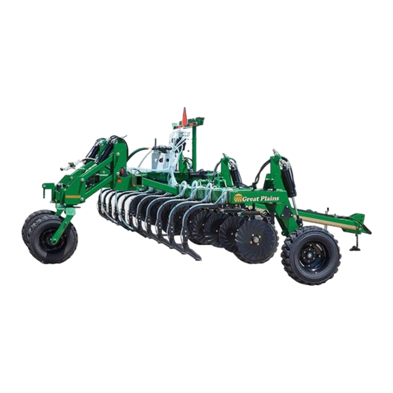
30- and 40-Foot NH
Read the operator manual entirely. When you see this symbol, the
subsequent instructions and warnings are serious - follow without
exception. Your life and the lives of others depend on it!
Illustrations may show optional equipment not supplied with standard unit, or
may show NP30L, NP40L or NP3000 models where the topic function is
identical.
ORIGINAL INSTRUCTIONS
© Copyright 2019
Table of Contents
Index
Operator Manual
®
Nutri-Pro
NP30A and NP40A
(Anhydrous Ammonia)
3
Manufacturing, Inc.
www.greatplainsmfg.com
Printed 2019-03-11
Index
Applicators
38809
EN
407-502M
Advertisement
Table of Contents

Related Manuals for GREAT PLAINS Nutri-Pro NP40A


Summary of Contents for GREAT PLAINS Nutri-Pro NP40A
- Page 1 Table of Contents Index Operator Manual ® Nutri-Pro NP30A and NP40A 30- and 40-Foot NH (Anhydrous Ammonia) Applicators Manufacturing, Inc. www.greatplainsmfg.com Read the operator manual entirely. When you see this symbol, the subsequent instructions and warnings are serious - follow without exception.
- Page 2 Machine Identification Record your machine details in the log below. If you replace this manual, be sure to transfer this information to the new manual. If you or the dealer have added options not originally ordered with the machine, or removed options that were originally ordered, the weights and measurements are no longer accurate for your machine.
- Page 3 Great Plains Manufacturing, Inc. assumes no responsibility for errors or omissions. Neither is any liability assumed for damages resulting from the use of the information contained herein. Great Plains Manufacturing, Inc. reserves the right to revise and improve its products as it sees fit.
- Page 4 NP30A or NP40A Cover Index Hydraulic Depth Stop Adjustment Pull-Type ....85 Normal Discharge ..........115 2- and 3-Point Height ..........86 Clearing Plugged Knives or Tines .........117 Weight Transfer Adjustment ..........87 Clearing Plugged Application Tubes ......117 Weight Transfer Safety Information......87 Clearing Plugged Vapor Tubes ......118 3-Section, Pull-Type, and 2012- 2-Point Weight Hydrostatic Relief Valve Maintenance......119 Transfer ..............88...
-
Page 5: Squibb-Taylor
(breakaway coupler) Read all of these manuals. If you do not have the current edition of one or more, contact Great Plains for a replacement copy. EPA EHS (Extremely Hazardous Substance): Despite the common odor, anhydrous ammonia properties are dramatically different from those of household ammonia (dilute ammonium hydroxide) cleaning solutions. - Page 6 NP30A or NP40A Table of Contents Index Important Safety Information Look for Safety Symbol The SAFETY ALERT SYMBOL indicates there is a potential hazard to personal safety involved and extra safety precaution must be taken. When you see this symbol, be alert and carefully read the message that follows it.
- Page 7 NP30A or NP40A Table of Contents Index Important Safety Information Wear Protective Equipment (PPE) Wear clothing and equipment appropriate for the job. Avoid loose-fitting clothing. Waterproof, wide-brimmed hat Face shield, goggles or full face respirator. Prolonged exposure to loud noise can cause hearing impairment or loss.
- Page 8 NP30A or NP40A Table of Contents Index Important Safety Information Use Safety Chains (For all nurse tanks and drawn fertilizer applicators) Use safety chains to help control drawn machinery should it separate from tractor draw-bar. Use chain with a strength rating equal to or greater than the gross weight of towed machinery.
- Page 9 NP30A or NP40A Table of Contents Index Important Safety Information Use Safety Lights and Devices Slow-moving tractors and towed applicators can create a hazard when driven on public roads. They are difficult to see, especially at night. Use flashing warning lights and turn signals whenever driving on public roads.
- Page 10 NP30A or NP40A Table of Contents Index Important Safety Information Remain Clear of Overhead Lines If the fertilizer applicator contacts a power line, lethal voltage may be present on all metal parts. At higher voltage, the applicator does not need to be in line contact for the hazard to exist.
-
Page 11: Tire Safety
NP30A or NP40A Table of Contents Index Important Safety Information Tire Safety Tire changing can be dangerous. Employ trained personnel using correct tools and equipment. When inflating tires, use a clip-on chuck and extension hose long enough for you to stand to one side–not in front of or over tire assembly. - Page 12 Keep all safety decals clean and legible. Replace all damaged or missing decals. Order new decals from your Great Plains dealer. Refer to this section for proper decal placement. When ordering new parts or components, also request corresponding safety decals.
- Page 13 NP30A or NP40A Table of Contents Index Important Safety Information 38815 838-265C Amber Reflectors On front face of front tool bar near wing hinge; Pull-Type (shown): On outside face of lift-assist brackets; 2-Point: On the outside faces of casters; 3-Point Models: on the outside faces of lift assist brace weldments;...
- Page 14 NP30A or NP40A Table of Contents Index Important Safety Information 31618 115527-01 Danger: Bleed System ® On top of CDS-John Blue Impellicone flow divider; 1 total 31604 818-323C Danger: Possible Chemical Hazard On decal mount near Flo-Max™ coupler: 1 total 818-557C Danger: Peligro: Ingles (in Spanish, warning users to seek translation assistance...
- Page 15 NP30A or NP40A Table of Contents Index Important Safety Information 818-590C Danger: Hitch Crush On front of frame tube; 2 total 38815 838-599C Danger: Electrocution On frame tube near wing hinges; 2 total 38815 31529 848-534C (Squibb-Taylor FM125-2000) Danger: Safety Coupler On decal mount near Flo-Max™...
- Page 16 NP30A or NP40A Table of Contents Index Important Safety Information 818-337C Warning: Speed On front face of front tool bar, right of center; 1 total 38815 818-339C Warning: High Pressure Fluid Hazard Pull-Type: On top of left tongue tube near hitch, 1 total 38815 818-437C...
- Page 17 NP30A or NP40A Table of Contents Index Important Safety Information 31604 848-551C Warning: Towing On decal mount near Flo-Max™ coupler: 1 total See “Transport” on page 66 and “Hitching Nurse Tank” on page 70 for further information. 31528 Raven: (no part number) Warning: Ball Valve On the handle of each emergency shut-off ball valve of applicators manufactured prior to 2011;...
- Page 18 NP30A or NP40A Table of Contents Index Important Safety Information 31050 818-398C Caution: Tires Not a Step 2-/3-Point: outside faces of manual gauge wheel arms; 2 total 818-587C Caution: Read Operator’s Manual On front face of front tool bar, right of center; 1 total 38815 818-719C...
- Page 19 NP30A or NP40A Table of Contents Index Important Safety Information CAUTION To Avoid Injury or Machine Damage from Improper Tire Inflation or Torquing of Wheel Bolts: Maximum inflation pressure of tires is 60 psi. Torque wheel bolts to 90 - 105 ft-lb. 838-092C 838-092C Caution: Tire Pressure and Bolt Torque...
- Page 20 NP30A or NP40A Table of Contents Index Important Safety Information CAUTION To Avoid Injury or Machine Damage from improper Tire Inflation or Torquing of Wheel Bolts: Maximum inflation pressure of tires is 90 psi. Torque wheel bolts to 90 - 105 ft-lb. 838-595C 838-595C Caution: Tire Pressure and Bolt Torque...
-
Page 21: Wash Water
NP30A or NP40A Table of Contents Index Important Safety Information CAUTION To Avoid Injury or Machine Damage from Improper Tire Inflation or Torquing of Wheel Bolts: Maximum inflation pressure of tires is 90 psi. Torque wheel bolts to 300 ft-lb. 858-021C 858-021C Caution: Tire Pressure and Bolt Torque... -
Page 22: Document Family
NP30A or NP40A Table of Contents Index Introduction Great Plains welcomes you to its growing family of new product owners. The 30- and 40-Foot NH (Anhydrous Ammonia) Applicators (NP30A or NP40A) has been designed with care and built by skilled workers using quality materials. - Page 23 NP30A or NP40A Table of Contents Index Introduction Using This Manual This manual will familiarize you with safety, assembly, operation, adjustments, troubleshooting, maintenance. Read this manual and follow the recommendations to help ensure safe and efficient operation. The information in this manual is current at printing. Some parts may change to assure top performance.
- Page 24 Index Introduction Owner Assistance If you need customer service or repair parts, contact a Great Plains dealer. They have trained personnel, repair parts and equipment designed for Great Plains products. Refer to Figure 2 and Figure 3 M od # NP Your machine’s parts were specially designed and...
-
Page 25: Single Cooler
NP30A or NP40A Table of Contents Index Metering Overview Legend: Anhydrous Flow Diagram Liquid NH Liquid Flow Single-Cooler Configuration - see pages 144 through Vapor Vapor Flow 147 for dual-cooler and single-section. Direction of Flow Exception Flow Callout numbers A11 through A86 identify the same applicator and cart components throughout this manual. - Page 26 NP30A or NP40A Table of Contents Index Metering Overview Systems Overview This list describes a single-cooler system. A dual-cooler A14.Breakaway Coupler system has two of components through , and two additional dual-tube knives or tines Refer to Figure 4 on page 21 Upon Event: Probable Chemical Hazard: A11.
- Page 27 NP30A or NP40A Table of Contents Index Metering Overview A16.Coupler Outlet Bleed Valve A23.Cooler Hydrostatic Relief Valve In normal operation, this valve never activates. NH can get trapped in the system between the emergency shut-off valve and the On/Off Suffocation, Blinding and Burning Hazards: valve , if both valves are closed while the system See “About Bleed Valves:”...
-
Page 28: Section Control
NP30A or NP40A Table of Contents Index Metering Overview A28.Pressure Gauge A31.Master Shut-Off Valve This gauge reports the pressure of the NH after it This is the normal control for starting and stopping exits the cooler. If line valves are closed, a pressure application flow in the field (for turns, etc.). -
Page 29: Shut-Off
NP30A or NP40A Table of Contents Index Metering Overview A37.Section Control Relief Valve A42.Flow Divider Pressure Gauge (Section Control Option Only) This gauge reports the pressure prior to flow In normal operation, this valve never activates. division. It normally reads lower than the cooler and can get trapped in the system between the nurse tank pressure gauges. - Page 30 NP30A or NP40A Table of Contents Index Metering Overview The following callouts are for trailing nurse tank cart A58.Outlet Hose Assembly components. See the “Using Anhydrous Ammonia The hose may have zero, one or two operating Safely” manual (407-551M) for all nurse tank callouts valves , one or more bleed valves , and a...
- Page 31 NP30A or NP40A Table of Contents Index Metering Overview A61.Bleed Valve(s) A65.Withdrawal Valve In field operations, this valve is opened first, and closed first. Suffocation, Blinding and Burning Hazards: Be up-wind when operating a bleed valve. Wear chemical gloves when operating a bleed valve. Wear goggles when operating a bleed valve.
- Page 32 Anhydrous Ammonia Release Hazard: Do not modify the NH system of this applicator. Use only the Great Plains rear hitch for a trailing nurse tank Designing NH systems, selecting and installing components is cart. A custom hitch and/or mount, including any safety chain serious engineering.
- Page 33 NP30A or NP40A Table of Contents Index Preparation and Setup Get Expert Advice Anhydrous ammonia is 82% Nitrogen, the highest of any fertilizer. The compound NH is normally a gas at ambient temperatures. It is retained in the soil only by chemical reactions and physical mechanisms, primarily reactions with soil moisture.
- Page 34 NP30A or NP40A Table of Contents Index Preparation and Setup Hitching Tractor to Applicator This manual presumes the following (recommended) operations sequence: 1. Hitch tractor to applicator for transport Loss of Control / Public Safety Hazards: 2- and 3-Point Hitching: page 31 Do not transport on public roads with a nurse tank hitched to Pull-Type Hitching: below the applicator.
- Page 35 NP30A or NP40A Table of Contents Index Preparation and Setup 2- and 3-Point Hitching The NP30A or NP40A is engineered to be used with Category II or Category III tractors. Crushing Hazard: Refer to Figure 7 Do not stand or place any body part between This applicator is factory set for Category III tractors.
- Page 36 NP30A or NP40A Table of Contents Index Preparation and Setup Emergency Shut-Off Rope This part of hitching requires operating the emergency shut-off valve. If the applicator was correctly shut down and discharged after last use, there is no anhydrous ammonia liquid in the system, and only small amounts of vapor, at low pressure.
- Page 37 NP30A or NP40A Table of Contents Index Preparation and Setup Refer to Figure 11 2. Check the pressure gauge . If it is not 0, STOP. Discharge the system before resuming hitching. See page 115. 3. From up-wind, and with the bleed valve orifice pointing away from you, slowly open the cooler bleed valve If any liquid appears, or vapor at high...
- Page 38 NP30A or NP40A Table of Contents Index Preparation and Setup Electrical Hookup Refer to Figure 13 Your fertilizer applicator is equipped with systems that require separate electrical connections. For future reference, note any optional connectors on this checklist. Lighting connector (standard) Rate Controller connector (standard) ...
- Page 39 NP30A or NP40A Table of Contents Index Preparation and Setup Hydraulic Hose Hookup High Pressure Fluid Hazard: Shut down tractor before making hydraulic connections. Only trained personnel should work with system hydraulics. Escaping fluid under pressure can have sufficient pressure to penetrate the skin causing serious injury.
- Page 40 NP30A or NP40A Table of Contents Index Preparation and Setup Raise Parking Stands (2- and 3-Point Only) Slide-Up Stands Refer to Figure 16 Heavy Object Hazard: Use the lifting handle . Push leg against frame while raising or lowering. The leg weighs approximately 45 pounds (20 kg). The leg could cause injury if you lose control of it while raising or lowering.
- Page 41 NP30A or NP40A Table of Contents Index Preparation and Setup Parking Stand Clearance This applies to older 2-Point and 3-point models only. Parking stands must clear tractor tires for normal operations. See page 36 for stand operation. Refer to Figure 17 If the parking stand leg strikes any tractor component when swung up for stowage, relocate both parking stand...
- Page 42 NP30A or NP40A Table of Contents Index Preparation and Setup Leveling Applicator During initial setup and periodically throughout the season, check that the applicator runs level. When applying, the top of the main frame should be parallel to the ground, and level left to right. Set Application Depth Before checking...
- Page 43 NP30A or NP40A Table of Contents Index Preparation and Setup Pull-Type Hitch Leveling Refer to Figure 21 With the knives or tines 4 inches into the ground, the tool bar height is: 24 inches (61 cm) and normally requires a pull-type hitch height of: 16.75 inches (42.5 cm) measured from the bottom of the tongue to the ground.
-
Page 44: Speed Cal
Great Plains cannot assume any liability for results with equipment not supplied by Great Plains. Before first use, the SCS 450 must be programmed with system configuration data, consisting of various “CAL”... -
Page 45: Single Section
NP30A or NP40A Table of Contents Index Preparation and Setup Raven Data (Section Control) BOOM CAL SPEED METER VALVE Model Description 1 (LH) 2 (CTR) 3 (RH) NP30A-11C30 4 Rows 3 Rows 4 Rows NP30A-11R30 30-ft., 11-Row, 30-in. 120 in. 90 in. - Page 46 A speed sensor input allows the SCS 450 to determine and control application rates at arbitrary field speeds. Note: The Great Plains Raven AccuFlow™ and SCS 450 bundles do not include a speed sensor, nor the cable necessary to connect a Raven-compatible sensor or radar to the SCS 450 See page 131 for an available radar kit.
- Page 47 NP30A or NP40A Table of Contents Index Preparation and Setup Wash Water Refer to Figure 23 Empty the 10 gallon applicator First Aid Water tank. Refill it with fresh clean water. If the nurse tank cart is at hand, refill the nurse tank wash water as well. The water needs to be changed daily.
- Page 48 NP30A or NP40A Table of Contents Index Applicator Operating Instructions This section covers general operating procedures. Experience, machine familiarity, and the following information will lead to efficient operation and good working habits. Always operate farm machinery with safety in mind. Pre-Start Checklist Perform the following steps before transporting the ®...
-
Page 49: Transport Lock
NP30A or NP40A Table of Contents Index Applicator Operating Instructions Applicator Locks Channels, pins, latches and solenoid valves limit The lock set combinations vary by applicator width, hitch movement for various situations. Channels and pins type and year. Consult the following table for locks require operator attention. - Page 50 NP30A or NP40A Table of Contents Index Applicator Operating Instructions Pull-Type Applicators Refer to Figure 25 To install cylinder stops: 1. Fully raise applicator (page 50). Set lift circuit to Neutral. 2. Remove lock channel from storage location. 3. Place a lock channel on the lift cylinder rod of each cylinder to be locked.
-
Page 51: Wing Lock Pin
NP30A or NP40A Table of Contents Index Applicator Operating Instructions 4. If locking for maintenance, at the left wing lift cylinder, remove the rear pin of the depth stop clevis. Swing the clevis forward. Machine Damage Risk: Do not install a lock channel on the depth stop cylinder unless the clevis has been rotated clear of the cylinder rod. - Page 52 NP30A or NP40A Table of Contents Index Applicator Operating Instructions Outer Wing Fold Latches These pins are present only on NP40A models with 5-section wings (inner and outer wings). Refer to Figure 30 These latches are automatic, and should never require operator action.
-
Page 53: Fold / Field
NP30A or NP40A Table of Contents Index Applicator Operating Instructions 2013+ NP40A 2-Point Fold/Lift Circuit On 2-point 5-section NP40A applicators made in 2013 or later, the fold and lift cylinders share a single hydraulic circuit. Solenoid valves (controlled by a switch box), one or more passive valves, and mechanical locks control hydraulic sequencing. -
Page 54: Weight Transfer
NP30A or NP40A Table of Contents Index Applicator Operating Instructions Raising/Lowering Applicator When raising in the field, first turn off anhydrous flow. See page 76. Lift/lower procedures depend on applicator model, year and hitch type: • Pull-type applicators use six cylinders for lift/lower. The lift circuit is separate from the fold circuit. - Page 55 NP30A or NP40A Table of Contents Index Applicator Operating Instructions Raise/Lower Pull-Type Re-Phasing Pull-Type Lift System Five of the six lift cylinders are slaved to the left front In typical use during a single application operation, it is caster wheel cylinder, which has a hydraulic down stop. normal for the lift cylinders to get out of phase, resulting in uneven raising and lowering of the fertilizer applicator.
- Page 56 NP30A or NP40A Table of Contents Index Applicator Operating Instructions Raise/Lower 3-Point The height/depth of the center section of a 3-point fertilizer applicator is controlled entirely by the tractor hitch. The height of the wings is controlled by manually-set wing gauge wheels. Operator action during lift and lower is needed to control wing droop.
- Page 57 NP30A or NP40A Table of Contents Index Applicator Operating Instructions Raise/Lower 3-Section and 2012- 2-Point These instructions apply to 3-section applicators and 2012- 5-section applicator. 2013+ 5-section applicators, see page 55. Refer to Figure 33 (depicting an NP40L, which has the same hitch and hydraulic system) The front height of the applicator center section is controlled by the lower two tractor 3-point arms...
- Page 58 NP30A or NP40A Table of Contents Index Applicator Operating Instructions Lowering 3-Section 2012- 2-Point (Field, Unfolded) See sidebar for considerations on a first pass. First Pass Lowering: 1. Close the weight-transfer shut-off valve (page 53). • If lock channels are engaged on the rear lift-assist 2.
- Page 59 NP30A or NP40A Table of Contents Index Applicator Operating Instructions Raise/Lower 2013+ 5-Section These instructions apply to 2013 and later 5-section applicators. For 3-section applicator, and 2012- 5-section Gradual Crushing Hazard: applicators, see page 53. Do not rely on hydraulic pressure alone to keep the applicator raised.
- Page 60 NP30A or NP40A Table of Contents Index Applicator Operating Instructions Field Lift: 5-Section 2013+ These steps presume an unfolded applicator in field configuration (lift-assist locks out, spacers in, coulters in Gradual Crushing Hazard: ground). Do not rely on hydraulic pressure alone to keep the applicator raised.
- Page 61 NP30A or NP40A Table of Contents Index Applicator Operating Instructions Lower While Folded: 5-Section 2013+ These steps presume that the intention is parking or storage, on lift-assist locks and parking stands. Tip-Over and Crushing Hazard: Never unhitch without using parking stands, particularly while 1.
- Page 62 NP30A or NP40A Table of Contents Index Applicator Operating Instructions Field Lower: 5-Section 2013+ These steps are for lowering in the field after initial line-up and after turns. Lift-assist lock channels (page 45) are presumed to have been replaced by spacers (page 38).
-
Page 63: Transport Rest
NP30A or NP40A Table of Contents Index Applicator Operating Instructions Unfolding and Folding ® Nutri-Pro applicators differ in locks and operational steps: • Pull-Type applicators have a simple dedicated fold Loop Ammonia Exposure Hazard: system with no wing locks. See “Unfolding and Allow no one down-wind of the applicator when folding and Folding Pull-Type”... - Page 64 NP30A or NP40A Table of Contents Index Applicator Operating Instructions Unfolding and Folding 3-Point Unfolding 3-Point The 3-Point applicator should only be unfolded in the field, or fully supported by parking stands. Ammonia Exposure Hazard: Unfolding 3-Point (At Field) Face applicator up-wind or clear the delivery lines (page 116) before unfolding.
- Page 65 NP30A or NP40A Table of Contents Index Applicator Operating Instructions Unfolding and Folding 3-Section and 2012- 2-Point 5-Section Unfolding 3-Section and 2012- 2-Point 5-Section Ammonia Exposure Hazard: Face applicator up-wind or clear the delivery lines (page 116) The 2-Point applicator should only be unfolded in the before unfolding or folding.
- Page 66 NP30A or NP40A Table of Contents Index Applicator Operating Instructions Folding 3-Section and 2012- 2-Point 5-Section These instructions presume that the applicator is unfolded and lowered. Ammonia Exposure Hazard: Face applicator up-wind or clear the delivery lines (page 116) before folding. Fluid in line loops, whether pure NH concentrated NH OH, is likely to move from the loops and drip out at the knives or tines.
- Page 67 NP30A or NP40A Table of Contents Index Applicator Operating Instructions Unfolding Folding 2013+ 2-Point 5-Section Unfolding 2013+ 5-Section (At Field) These instructions presume the applicator has just completed transport, is raised, and transport locks are installed. It is being unfolded for field use. 1.
- Page 68 NP30A or NP40A Table of Contents Index Applicator Operating Instructions Unfolding 2013+ 5-Section (Parking, Storage, Service) To unfold, off field, for parking, storage or servicing, unfold with the center section fully raised. 1. Hitch to a suitable tractor (page 30). 2.
- Page 69 NP30A or NP40A Table of Contents Index Applicator Operating Instructions Folding 2013+ 5-Section These instructions presume that the applicator is unfolded and lowered. 1. Verify that the wing lock pins (page 47) are not in the wing rest cradles. Typically they are in storage tubes. Refer to Figure 47 2.
- Page 70 NP30A or NP40A Table of Contents Index Applicator Operating Instructions Transport Loss of Control Hazard: Never use the applicator to tow a nurse tank on public roads. Tow the tank to the field with a separate vehicle. The applicator cannot provide sufficient lateral control of a trailing cart at highway speeds.
- Page 71 NP30A or NP40A Table of Contents Index Applicator Operating Instructions Transport Steps Know your applicator weight. See page 136 or page 139 tables including approximate weights representative configurations. If tractor capabilities are marginal, check the actual weight of the applicator at a scale. Pull-Type Applicators 2-Point and 3-Point Applicators 1.
- Page 72 NP30A or NP40A Table of Contents Index Applicator Operating Instructions Nurse Tanks Use nurse tanks with proper current safety certification, and current safety equipment and features. Consult with your anhydrous ammonia supplier for safety information and correct safe handling, transport and use of anhydrous ammonia.
- Page 73 Index Applicator Operating Instructions Check Hydrostatic Relief Valves 3. Check that the plastic cap is in place at each valve. In the Great Plains configuration, this would be: • at each cooler • at the outlet side of the breakaway coupler...
- Page 74 NP30A or NP40A Table of Contents Index Applicator Operating Instructions Hitching Nurse Tank Consult with the nurse tank supplier, and all available nurse tank documents, before hitching for the first time. : Possible Chemical Hazard: Clear all non-essential personnel from the area at this time. Take normal NH field precautions.
- Page 75 NP30A or NP40A Table of Contents Index Applicator Operating Instructions Making Nurse Tank Connections These instructions presume an applicator with Great Plains-supplied Squib-Taylor Flo-Max™ coupler and Raven AccuFlow™ application system. 1. Perform the steps at “Safing Applicator Before Cart Hitch”, pages 68. Anhydrous Ammonia Exposure Hazard: Do not skip step 1.
- Page 76 NP30A or NP40A Table of Contents Index Applicator Operating Instructions Connect Cart Hose Refer to Figure 57 Continue wearing your NH 7. Verify that the nurse tank hose withdrawal valve is closed. Hand tighten only. Do not use tools. 8. Verify that any hose valves ( , not shown here) are also closed.
- Page 77 NP30A or NP40A Table of Contents Index Applicator Operating Instructions Pass Planning If field requirements permit, you can minimize exposure WIND to NH vapor with the following recommendations: Refer to Figure 58 • Check the wind direction. • Plan passes to be cross-wind and turns up-wind. •...
- Page 78 NP30A or NP40A Table of Contents Index Applicator Operating Instructions Monitor Operation Refer to Figure 59 The optional SCS 450 console monitors NH flow, monitors field speed, and operates the (rate) control valve to deliver anhydrous ammonia at your desired rate. Once setup for the applicator and preferences, and configured for the rates/limits, the monitor is typically used in the “RATE 1”...
-
Page 79: Starting Application
, if any - tank A61b depicted has no hose valves). Check for leaks. In an all-Great Plains configuration, if there has been no odor so far, there should be no odor now, as flow is blocked at the On/Off valve (not visible). - Page 80 NP30A or NP40A Table of Contents Index Applicator Operating Instructions Suspending Application These instructions are for brief stops in the field, for example, to make a phone call. See also “Stopping Application” on page 77. a. What is the wind direction? Choking Hazard: Never raise a recently operated applicator when you are b.
- Page 81 NP30A or NP40A Table of Contents Index Applicator Operating Instructions Stopping Application Plan your stops. A safe stop requires depleting the anhydrous, from the nurse tank withdrawal valve to the knives or tines. a. What is the wind direction? b. Suspend application per “Suspending Application” on page 76.
- Page 82 NP30A or NP40A Table of Contents Index Applicator Operating Instructions Breakaway Event Initially treat a breakaway coupler separation event as you would any other field emergency. Perform the steps at “Ammonia Emergency Action” in the “Using Upon Event: Probable Chemical Hazard: Anhydrous Ammonia Safely”...
- Page 83 NP30A or NP40A Table of Contents Index Applicator Operating Instructions 11. Opening this bleed valve WILL release the substantial amount of liquid NH presently trapped in the hose, most likely as a spray. Open the valve very slowly, just until some fluid appears. Leave the valve just slightly open.
-
Page 84: Unhitching Nurse Tank
NP30A or NP40A Table of Contents Index Applicator Operating Instructions Unhitching Nurse Tank The procedure is different for exchanging tanks vs. concluding application. Exchanging Nurse Tanks Consult with the nurse tank supplier, and all nurse tank documents, before unhitching or exchanging tanks. a. - Page 85 NP30A or NP40A Table of Contents Index Applicator Operating Instructions Field Set-Up Checklists Use the following tables to develop a final checklist for your tractor/fertilizer applicator configuration. Additional or fewer steps may be necessary depending on tractor features, fertilizer applicator options and accessories. Mechanical Checklist (post-Hitching) Page Mechanical Checklist (Tractor Hitching)
- Page 86 NP30A or NP40A Table of Contents Index Applicator Operating Instructions Field Operation Checklists Perform all steps in “Pre-Start Checklist” on page 44 and “Field Set-Up Checklists” on page 81. First Pass Operation Checklist Page Suspending Application Checklist Page Set console MASTER switch OFF Raise fertilizer applicator.
- Page 87 NP30A or NP40A Table of Contents Index Applicator Operating Instructions Long-Term Storage Ending Application Checklist Page 1. Conclude application per “Stopping Application” on Suspend operations as at left, then… page 77. Put on your goggles and gloves 2. Unhitch nurse tank per “Final Nurse Tank Unhitch” on page 80.
-
Page 88: Anhydrous Coulter
NP30A or NP40A Table of Contents Index Adjustments To get full performance from your NP30A or NP40A Even if your application conditions rarely change, some fertilizer applicator, you need an understanding of all of these items need periodic adjustment due to normal component operations, and many provide adjustments wear. - Page 89 NP30A or NP40A Table of Contents Index Adjustments Frame Height Adjustments Hydraulic Depth Stop Adjustment Pull-Type This applies to pull-type applicators only. The lift system includes an adjustable stop valve, on the left front caster wheel, to fix the height of the opener frame when the applicator is lowered.
- Page 90 NP30A or NP40A Table of Contents Index Adjustments 2- and 3-Point Height This applies to 2-point and 3-point applicators only. Center section tool bar height is set by the tractor hitch. Wing end tool bar height is set by independent gauge wheels on each wing end.
- Page 91 NP30A or NP40A Table of Contents Index Adjustments Weight Transfer Adjustment Weight Transfer Safety Information Anhydrous Ammonia Exposure Hazard: Make this adjustment only on a fully discharged applicator. Knives or tines are likely to raise and lower during adjustment, and may rise out of the ground altogether. If the applicator has recently been used for application, wear your Crushing and High Pressure Fluid Hazards: This adjustment requires working near the unfolded and...
- Page 92 NP30A or NP40A Table of Contents Index Adjustments 3-Section, Pull-Type, and 2012- 2-Point Weight Transfer For 2013+ 2-Point 5-Section weight transfer, see page 90. See important safety information on page 87. Description of system Note: See circuit diagrams in the Appendix starting on Page 148.
- Page 93 NP30A or NP40A Table of Contents Index Adjustments Adjusting the Weight-Transfer Refer to Figure 66 1. In field conditions, unfold (page 59), lower applicator (page 50), and set or check application depth (page 96). 2. Pull forward to put coulters in ground. 3.
- Page 94 NP30A or NP40A Table of Contents Index Adjustments 2013+ 2-Point 5-Section Weight Transfer For 3-Section, Pull-Type, and 2012- 2-Point 5-Section, see page 88. See important safety information on page 87. Description of system Note: See circuit diagrams in the Appendix starting on Page 148.
- Page 95 NP30A or NP40A Table of Contents Index Adjustments Adjusting the Weight-Transfer Note: See circuit diagrams in the Appendix starting on Page 148. Refer to Figure 66 1. In field conditions, unfold applicator (page 59). 2. Set FOLD / FIELD to FIELD. 3.
- Page 96 NP30A or NP40A Table of Contents Index Adjustments Wing Leveling Before checking wing level, check that the center section is level left to right (“Rear Eyebolt Adjustment”). On 2-point and pull-type, rear eyebolts above the rear casters can affect left-right level if out of adjustment. Wing Level: 2- and 3-Point On 2-point and 3-point applicators, wing level is controlled entirely by gauge wheel height.
-
Page 97: Unfold Stop
NP30A or NP40A Table of Contents Index Adjustments Unfold Stop Adjustment This applies to 2103+ 5-Section applicators only. Refer to Figure 70 During unfold (FOLD / FIELD switch in FOLD), the inner wing sections are intended to stop 0 to 5° above wings-level relative to the center section . - Page 98 NP30A or NP40A Table of Contents Index Adjustments Field Fold Stop Adjustment This applies to 2103+ 5-Section applicators only. Refer to Figure 71 During field fold (FOLD / FIELD switch in FIELD), the inner wing sections are intended to stop 5 to 10° above wings-level relative to the center section .
- Page 99 NP30A or NP40A Table of Contents Index Adjustments Caster Brake Adjustment Refer to Figure 72 The rear lift-assist wheels each have independent adjusters for the caster pivot brake. The piston acts as a pivot brake, and helps prevent caster oscillation during transport.
- Page 100 NP30A or NP40A Table of Contents Index Adjustments Application Depth Rigid Knife Release Depth Refer to Figure 74 Knife release depth is set by tool bar height above the ground. Control of height depends on hitch type. Pull-Type applicators have an adjustable hydraulic down-stop for controlling tool bar height (page 85).
- Page 101 NP30A or NP40A Table of Contents Index Adjustments Spring Knife Release Depth Refer to Figure 75 Knife release depth is set by tool bar height above the ground. Control of height depends on hitch type. Pull-Type applicators have an adjustable hydraulic down-stop for controlling tool bar height (page 85).
-
Page 102: Tine Height
NP30A or NP40A Table of Contents Index Adjustments Anhydrous Coulter Application Depth Refer to Figure 76 Tine release depth is set by tool bar height above the ground, coulter shank height and tine height Chemical Hazard: Adjust height dry. Make adjustments before charging the metering system with anhydrous ammonia, or after thoroughly discharging the system. - Page 103 NP30A or NP40A Table of Contents Index Adjustments Row Implement Adjustments Frame-Mounted Coulters (Option) Refer to Figure 77 Coulters are factory-installed if ordered with the implement, and are configured for in-row operation at knife or tine shoe depth. They can be set for fixed or limited castering.
-
Page 104: Spring Shank
NP30A or NP40A Table of Contents Index Adjustments Knife Adjustment Refer to Figure 79 Knives have no adjustments. Application depth is set by the tool bar (page 96). Knives have (Grade 5) shear bolts . Should the knife encounter a substantial obstruction, such as a large rock, or if speed plus conditions are too challenging, the shear bolt fails, and the knife swings back on the (Grade 8) mounting bolt... - Page 105 NP30A or NP40A Table of Contents Index Adjustments Anhydrous Coulter Spring Setting If the NH coulter is ever disassembled for maintenance, reset the spring length to factory setting. Raise the applicator to ensure that the coulter is relaxed. Refer to Figure 81 At the rear end of the spring , loosen the outer jam nut.
- Page 106 NP30A or NP40A Table of Contents Index Adjustments Sealer Adjustments The sealers close the trench behind the knives or tines, manage residue. Adjustable to control or avoid berm. Knife/Tine Spider Sealer Adjustments Refer to Figure 83, 84 and Figure 85 on page 103 To provide consistent action, the sealer wheels and discs are free to move downward from their normal operating position.
- Page 107 NP30A or NP40A Table of Contents Index Adjustments Sealer Down Pressure Factory setting is the front hole. Additional sealer down-force is available by moving the spring adjustment weldment to the rear. To change: a. Lower the applicator until the sealer wheels or disc are in ground contact, and the arms are lifted above both down-stop holes .
- Page 108 NP30A or NP40A Table of Contents Index Adjustments Anhydrous Coulter Sealer Adjustments The spider sealers have three adjustments. You may need to alter these from factory settings, based on soil conditions, crop residue and application speed. Refer to Figure 86 1.
-
Page 109: Depth Stop
Table of Contents Index Troubleshooting The topics in this section presume that the applicator has Troubleshooting sections are also found in the following a Great Plains-supplied Raven SCS 450 console, Raven component manuals: ® AccuFlow™ metering system, and CDS-John Blue 016-0159-403 ®... -
Page 110: Shear Bolt
NP30A or NP40A Table of Contents Index Troubleshooting General Applicator Troubleshooting Problem Cause Solution loss to atmosphere See “Clearing Plugged Knives or Tines” on (one row) page 117. If knives or tines are plugging frequently, Plugged knife or tine check: coulter setup, application depth, knife/tine wear. -
Page 111: Field Fold
NP30A or NP40A Table of Contents Index Troubleshooting FOLD / FIELD Troubleshooting (2013+ 5-Section only) Problem Cause Solution Fold or Unfold Abnormal Circuit to solenoid valves broken, typically a Check harness connections at hitch, then, with Switch Box Indicator disconnected harness at hitch check for 12 Vdc at solenoids. - Page 112 NP30A or NP40A Table of Contents Index Troubleshooting Metering System Troubleshooting Problem Cause Solution Stop application per page 77. Lift applicator and inspect knives or Pressure Spikes (no Plugged knives or tines tines. Clear any plugging per “Clearing Plugged Knives or Tines” alarm) on page 117.
- Page 113 NP30A or NP40A Table of Contents Index Troubleshooting Metering System Troubleshooting Problem Cause Solution Stop application per page 77. Lift applicator and inspect knives or Rows Not Fertilized Check for plugged row-unit tube tines. Clear any plugging per “Clearing Plugged Knives or Tines” on page 117.
-
Page 114: General Application
NP30A or NP40A Table of Contents Index Troubleshooting General Application Troubleshooting Problem Cause Solution Field size different. After ruling out metering problems, re-check geography. Excess Material Excessive gaps between applicator Gap between opposing pass end trenches should be one row Remaining passes. - Page 115 NP30A or NP40A Table of Contents Index Troubleshooting General Application Troubleshooting Problem Cause Solution loss to See “Clearing Plugged Knives or Tines” on page 117. atmosphere If tines are plugging frequently, check: coulter setup, (one row) Plugged tine application depth, tine wear. Field conditions and weather may also be unsuitable at the moment.
- Page 116 NP30A or NP40A Table of Contents Index Maintenance and Lubrication Maintenance Proper servicing and maintenance is the key to long applicator life. With careful and systematic inspection, you can avoid costly maintenance, downtime, and repair. Always turn off and remove the tractor key before making any adjustments or performing any maintenance.
-
Page 117: Withdrawal Valve
NP30A or NP40A Table of Contents Index Maintenance and Lubrication Avoid Trapped Anhydrous Before servicing anhydrous equipment, or storing it near untrained individuals, be absolutely certain that there is no liquid NH trapped in the system, and no NH vapor present (or only trace amounts). - Page 118 NP30A or NP40A Table of Contents Index Maintenance and Lubrication Avoid Ball Traps IDLH Anhydrous Ammonia Exposure Hazard: Beware of closed ball valves. A ball valve can trap liquid NH If opened when disconnected, this liquid is likely at extreme pressures, is emitted forcefully and vaporizes rapidly.
-
Page 119: Stopping Application
NP30A or NP40A Table of Contents Index Maintenance and Lubrication System Discharge These steps are for clearing an applicator for service or for storage near untrained persons. These instructions presume that you have followed the steps at: “Stopping Application” on page 77, Suffocation, Blinding, Burning, Freezing, Disabling and and the nurse tank is unhitched, per: Disfigurement Hazards:... -
Page 120: System Blow-Out
NP30A or NP40A Table of Contents Index Maintenance and Lubrication System Blow-Out 4. To rapidly reduce the vapor in the system to trace amounts, use compressed air at the Acme inlet If there is ammonium hydroxide (NH OH) fluid (or a. - Page 121 NP30A or NP40A Table of Contents Index Maintenance and Lubrication Clearing Plugged Knives or Tines Knives or tines can get plugged at release ports , due to sticky soil, reverse movement and other causes. Routinely check knives or tines for evidence of plugging just prior to nurse tank hitching.
-
Page 122: Temperature Gauge
NP30A or NP40A Table of Contents Index Maintenance and Lubrication Clearing Plugged Vapor Tubes Elevated Ammonia Exposure Hazard: Follow clearing instructions carefully. Wear your PPE Plugged vapor tubes with tubing still attached can contain significantly greater than normal NH vapor which is not likely to be mitigated by normal Discharge procedures. - Page 123 NP30A or NP40A Table of Contents Index Maintenance and Lubrication Hydrostatic Relief Valve Maintenance Relief valves require scheduled replacement and periodic inspection. Ammonia Exposure Hazards: Relief Valve Inspection Wear safety equipment when inspecting or performing maintenance on relief valves. Even if the line is bled, NH Inspect relief valves seasonally, and during periodic liquid or vapor may still be present.
- Page 124 that is rated for the same discharge pressure as the valve specialized equipment, to discharge at a specific removed (or as otherwise specified by Great Plains or the pressure. manufacturer of the protected component). On the component being protected by the valve, inspect the threaded hole after removing the valve.
-
Page 125: Supply Hose
Certain components and fittings used with anhydrous ammonia service have limited service lives. The service life of components originally installed by Great Plains is pre-printed in the tables. The life of replacement parts may vary. Once past their expiration dates, they must be replaced before the applicator is used again to apply anhydrous, even if they appear to be in excellent condition. - Page 126 Cooler Hydrostatic Relief Valve Part ID Service Life Date Life Started Replace Before Date Raven or Great Plains 5 years: the replace-by date is 334-0002-005 stamped on the valve. Refrigerant Line This is the same tubing used for row delivery...
- Page 127 Part ID Service Life Date Life Started Replace Before Date Great Plains 10 Year rated life 990-259R Row Vapor Tubing This is a different (larger ID) tubing compared to the row delivery and refrigerant tubing.
- Page 128 NP30A or NP40A Table of Contents Index Maintenance and Lubrication Metering System Maintenance Fully discharge system before performing maintenance. See “System Discharge” on page 115. Suffocation, Blinding, Burning, Freezing, Disabling and Disfigurement Hazards: If any system components are removed from plumbing, Do not perform maintenance with anhydrous ammonia in the when replacing or re-installing them, use only a pipe system.
- Page 129 Crushing Hazard: JIC Torque Chart When reconnecting fittings at fold cylinder ports, verify that a 0.063 inch ( inch, 1.6 mm) orifice plate (Great Plains part Size Foot-Pounds number 196-430D) is installed at each port. A missing plate 11-12...
- Page 130 NP30A or NP40A Table of Contents Index Maintenance and Lubrication Bleeding Fold Hydraulics Normally the fold hydraulics are bled at the factory before shipping, and bleeding should not be required. 1. Connect the fold circuit to a hydraulic source, such Crushing and Equipment Damage Hazards: as a tractor remote.
-
Page 131: Wing Pivots
NP30A or NP40A Table of Contents Index Maintenance and Lubrication Lubrication and Scheduled Maintenance Intervals (operating hours) Multi-purpose Multi-purpose Multi-pupose Inspection at which service oil lubricant spray lubricant grease lubricant is required See “Replacement Log” on page 121 for components that require replacement at specific calendar dates. - Page 132 NP30A or NP40A Table of Contents Index Maintenance and Lubrication Basket Sealer Bearings (Option) 1 zerk per bearing, 2 bearings per basket; 22 to 30 zerks total Type of Lubrication: Grease Quantity: Until grease emerges 31702 Caster Wheel Parallel Arms (2-Point and Pull-Type applicators only) 2 zerks each arm, 2 arms per caster,...
-
Page 133: Tire Pressure
NP30A or NP40A Table of Contents Index Maintenance and Lubrication Coulter Hubs (Option) 1 zerk per coulter, 11 to 15 total Type of Lubrication: Grease Quantity: Until grease emerges 31598 Coulter Pivots (Option) 1 zerk per coulter pivot, 11 to 15 total Type of Lubrication: Grease Quantity: Until grease emerges 31597... - Page 134 NP30A or NP40A Table of Contents Index Maintenance and Lubrication Disc Sealer Hubs (Option) 31071 Seasonal Applies to knife/tine sealers only. 2 races per hub, 2 hubs per sealer, 11 to 15 sealers per applicator; 44 to 60 races total Type of Lubrication: Grease Quantity: Repack Pull-Type Caster Wheel Hubs...
-
Page 135: Speed Sensor Cable
The Raven SCS 450 accepts speed inputs from traditional magnet sensors, speed radars, and GPS receivers that provide compatible speed outputs. If the tractor does not already have a compatible speed data ® source, Great Plains offers a DICKEY-john radar. Option Package Part Number Radar Kit... - Page 136 Part Number CAT 2 HITCH PIN KIT 596-060A 31077 Metering Based on the Raven AccuFlow™ system, Great Plains 31582 factory-installed systems include all the components identified on pages 144 through page 147, plus all the piping, tubing, fittings and console harness to hitch.
-
Page 137: Large Spider
NP30A or NP40A Table of Contents Index Options Frame-Mounted Coulters ® If ordered with the Nutri-Pro applicator, coulters are factory-installed, aligned with knives or tines (in-row) and set for fixed (non-castering) operation. Choose between fluted and turbo 20 inch blades (turbo shown at right). Coulter Package Original Option Fluted Coulters... -
Page 138: Spider Sealer
NP30A or NP40A Table of Contents Index Options Knife Row Sealers ® If ordered with the Nutri-Pro applicator, sealers are factory-installed. Choose between spider wheel or disc blades. The sealer kits include adjustable spring-loaded mounts . Kits may be field-installed. Sealer Package Original Option Basket Sealers... - Page 139 A rear hitch is required for a trailing nurse tank. An optional drop rear hitch is available. The assembly offered by Great Plains includes hitch mount weldment, decal mount (not shown), breakaway coupler mount point, and a Schuck model 850 cushioned hitch with a 50,000 pound load rating and 2,000 pound tongue weight.
-
Page 140: Metering System
1. Power requirements vary significantly with conditions and practices. 2. With Great Plains-installed AccuFlow metering, Schuck hitch, coulters and spider sealers. All weights are approximate. 3. Release depth is 3/4 in. above knife/tine depth, or 3/8 in. above coulter depth. - Page 141 1. Power requirements vary significantly with conditions and practices. 2. With Great Plains-installed AccuFlow metering, Schuck hitch, coulters and spider sealers. All weights are approximate. 3. Release depth is 3/4 in. above knife/tine depth, or 3/8 in. above coulter depth.
- Page 142 1. Power requirements vary significantly with conditions and practices. 2. With Great Plains-installed AccuFlow metering, Schuck hitch, coulters and spider sealers. All weights are approximate. 3. Release depth is 3/4 in. above knife/tine depth, or 3/8 in. above coulter depth.
- Page 143 1. Power requirements vary significantly with conditions and practices. 2. With Great Plains-installed AccuFlow metering, Schuck hitch, coulters and spider sealers. All weights are approximate. 3. Release depth is 3/4 in. above knife/tine depth, or 3/8 in. above coulter depth.
-
Page 144: Torque Values
NP30A or NP40A Table of Contents Index Appendix A - Reference Information Tire Inflation Chart Tire Warranty Information All tires are warranted by the original manufacturer of the tire. Tire Size Inflation Tire warranty information is found in the brochures included with your Operator’s and Parts Manuals or online at the 265/70B16.5 (10-16.5) NHS 8-Ply 60 psi (415 kPa) - Page 145 NP30A or NP40A Table of Contents Index Appendix A - Reference Information Controller System Diagram Single-Section Controller GP: 823-211C Accessories sold separately GP: 823-212C (GP: 115-0159-539) (GP: 823-215C) GP: 823-354C 31580 063-0172-977 GP: 063-0171-666 063-0172-978 2019-03-11 Table of Contents Index 407-502M...
- Page 146 NP30A or NP40A Table of Contents Index Appendix A - Reference Information Section Control Controller GP: 823-211C GP: 823-212C (GP: 115-0159-539) (GP: 823-215C) 115-0171-836 GP: 823-422C 34966 GP: 063-0171-666 063-0172-977 063-0172-978 063-0172-978 2019-03-11 Table of Contents Index 407-502M...
- Page 147 NP30A or NP40A Table of Contents Index Appendix A - Reference Information Plumbing Diagrams See page 22 for a narrative. System Elements The dual-cooler systems (page 146 and 147) differ from Legend: the single-cooler systems (page 144 and 145) as follows: Liquid NH Liquid Flow •...
- Page 148 NP30A or NP40A Table of Contents Index Appendix A - Reference Information Single-Cooler Single-Section Plumbing See legends on page 143 and “Systems Overview” on page 22. A43 A49 2019-03-11 Table of Contents Index 407-502M...
- Page 149 NP30A or NP40A Table of Contents Index Appendix A - Reference Information Single Cooler Section Control Plumbing See legends on page 143 and “Systems Overview” on page 22. 34959 2019-03-11 Table of Contents Index 407-502M...
- Page 150 NP30A or NP40A Table of Contents Index Appendix A - Reference Information Dual-Cooler Single-Section Plumbing See legends on page 143 and “Systems Overview” on page 22. A47 A19 34961 2019-03-11 Table of Contents Index 407-502M...
- Page 151 NP30A or NP40A Table of Contents Index Appendix A - Reference Information Dual Cooler Section Control Plumbing See legends on page 143 and “Systems Overview” on page 22. A48 A48 34962 2019-03-11 Table of Contents Index 407-502M...
- Page 152 NP30A or NP40A Table of Contents Index Appendix A - Reference Information Hydraulic Diagrams Hydraulic Schematic (2013+ 5-Section) 2-Point with Lift Assist 2019-03-11 Table of Contents Index 407-502M...
- Page 153 NP30A or NP40A Table of Contents Index Appendix A - Reference Information Proximity and Solenoid Locations (2013+ 5-Section) 2-Point with Lift Assist 2019-03-11 Table of Contents Index 407-502M...
- Page 154 NP30A or NP40A Table of Contents Index Appendix A - Reference Information Lift Assist and Fold Hydraulics: 2012- 2-Point 5-Section 34093 Shut-off valve Pressure reducing valve Bypass valve 2019-03-11 Table of Contents Index 407-502M...
-
Page 155: Lift-Assist
NP30A or NP40A Table of Contents Index Appendix A - Reference Information Lift Assist, Weight Transfer and Fold Hydraulics: 2013+ 2-Point 5-Section 34957 Weight-transfer valve 2019-03-11 Table of Contents Index 407-502M... - Page 156 NP30A or NP40A Table of Contents Index Appendix A - Reference Information Fold Hydraulics: Pull-Type 5-Section 38852 Shut-off valve Pressure reducing valve Bypass valve 2019-03-11 Table of Contents Index 407-502M...
- Page 157 NP30A or NP40A Table of Contents Index Appendix A - Reference Information Fold Hydraulics: 3-Point and Pull-Type 3-Section 31581 Shut-off valve Pressure reducing valve Bypass valve 2019-03-11 Table of Contents Index 407-502M...
- Page 158 NP30A or NP40A Table of Contents Index Appendix A - Reference Information Lift and Fold Hydraulics: 2-Point 3-Section 31578 Shut-off valve Pressure reducing valve Bypass valve 2019-03-11 Table of Contents Index 407-502M...
- Page 159 NP30A or NP40A Table of Contents Index Appendix A - Reference Information Lift Hydraulics: 2011+ Pull Type 31575 2019-03-11 Table of Contents Index 407-502M...
- Page 160 NP30A or NP40A Table of Contents Index Appendix A - Reference Information Lift Hydraulics: 2010- Pull Type 32025 2019-03-11 Table of Contents Index 407-502M...
- Page 161 Component Replacement Dates Record replace-by dates on the “Replacement Log”, pages 121 to 123. If the applicator has Great Plains-installed metering, several components of that system have limited service lives, and must be replaced before specific dates. Where these dates are stamped on metal parts, normal...
- Page 162 NP30A or NP40A Table of Contents Index Appendix B - Initial Setup Lift-Assist Valve Setup This applies to 2-Point applicators only. 1. Locate the one-way restrictor valve at the tee that supplies the rear cylinder base ends. 2. Turn the knob fully counterclockwise. Figure 95 31612 Lift-Assist Valve...
-
Page 163: Weight Kit
NP30A or NP40A Table of Contents Index Appendix C - Accessory Installation Weight Kit Installation 407-740A (NP4000) Weight Kit Installation Tools Required: • Lift or hoist with a capacity of at least 750 pounds (340 kg). Two lift lines, each with a capacity of at least 750 pounds (340 kg). - Page 164 NP30A or NP40A Table of Contents Index Appendix C - Accessory Installation 417-192A Weight Kit Installation Tools Required: • Lift or hoist with a capacity of at least 890 pounds (403 kg). Two lift lines, each with a capacity of at least 890 pounds (403 kg).
-
Page 165: Warranty
This Warranty is limited to the replacement of any defective part by Great Plains and the installation by the dealer of any such replacement part. Great Plains reserves the right to inspect any equipment or part which are claimed to have been defective in material or workmanship. -
Page 166: Coulter
NP30A or NP40A Cover Table of Contents Index caster pivots ........127 coulter caster stabilizer ........ 130 frame-mounted ....99 abnormal folding .........65 caster wheel parallel arms ....128 coulter castering .......101 ACA ..........124 Category II .........31 coulter hubs ........129 AccuFlow™... -
Page 167: Emergency
NP30A or NP40A Cover Table of Contents sealer ........104 inlet .............22 down-wind ..........73 installation gasket ..........26 drain cap ..........23 FOLD / FIELD......157 gauges dry run ........72 weight bracket ......159 pressure ......24 dual knife ..........25 intake, cooler ........23 pressure, tank ......27 dual tine ..........25 intended usage ........18 temperature ........ -
Page 168: Sealer
NP30A or NP40A Cover Table of Contents maintenance ........112 pin, wing lock ........47 SMV..........8 hydraulic ........125 piston ..........95 refrigerant line........24 MAN mode .........42 stabilizer ........130 refrigerant tap ........24 manifold inlet ........25 plastic sealant tape ......125 refrigeration ........23 MASTER ..........74 plug, flow divider ........ -
Page 169: Table Of Contents
NP30A or NP40A Cover Table of Contents shear bolt ..........100 section control ..... 41 vapor outlet .........25 shoe ..........96 single section ....... 40 vapor tubing ....... 25 shutdown ..........6 torque values ......140 vibration, caster ........95 shut-off troubleshooting weight transfer ......50 FOLD / FIELD .... - Page 170 NP30A or NP40A Cover Table of Contents 2-point leveling ........38 810-877C, valve .......148 2-point unfolding ......61 818-055C, reflector ......8 2, option ..........132 818-323C, decal ......... 10 20, option ..........132 818-337C, decal ......... 12 204-376M, manual ......99 818-339C, decal ......... 12 21, option ..........132 818-398C, decal .........
- Page 171 Table of Contents Index Table of Contents Index...
- Page 172 Great Plains, Mfg. 1525 E. North St. P.O. Box 5060 Salina, KS 67402...
Need help?
Do you have a question about the Nutri-Pro NP40A and is the answer not in the manual?
Questions and answers