Table of Contents
Advertisement
Quick Links
Advertisement
Table of Contents

Related Manuals for tissin TS800 Series


Summary of Contents for tissin TS800 Series
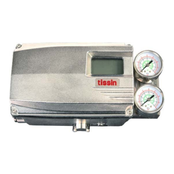
- Page 1 Smart Valve Positioner TS800 Series Instruction Manual Ver. PM-TS800EN-11/2018...
-
Page 2: Table Of Contents
Smart valve positioner tissin TS800 Series Table of Contents Introduction ------------------------------------------------------------------------------------- General information for the user---------------------------------------------------------- Requirement for safety---------------------------------------------------------------------- Basic safety instructions for use in the Ex area--------------------------------------- 1.3.1 Conditions to maintain intrinsic safety (Ex i)------------------------------------ 1.3.2 Data of Intrinsic safety explosion--------------------------------------------------... - Page 3 Smart valve positioner tissin TS800 Series 3.5.2 Installation of HART communication module-------------------------------- 3.5.3 Installation of Limit switch modules-------------------------------------------- 3.5.4 How to adjust limit switch cam -------------------------------------------------- How to adjust Auto/Manual switch ------------------------------------------------------- Orifice installation----------------------------------------------------------------------------- Pneumatic connection ---------------------------------------------------------------- Condition of air supply-----------------------------------------------------------------------...
-
Page 4: Introduction
For additional information or if specific problems occur that are not explained in these instructions, contact the manufacturer. The manual can be altered or revised due to hardware of software upgrades without any prior notice. Please visit our website ( www.tissin.co.kr ) and check the latest documentation. Manual version PM-TS800EN-11/2018 Software version V.2.00... -
Page 5: Requirement For Safety
Smart valve positioner tissin TS800 Series Requirements for safety This manual contains notices you have to observe in order to ensure your personal safety, as well as to prevent damage to property. These safety instructions are intended to prevent hazardous situations and/or equipment damage. For the safety, it is important to follow the instructions in the manual. -
Page 6: Basic Safety Instructions For Use In The Ex Area
Smart valve positioner tissin TS800 Series Basic safety instructions for use in the Ex area To prevent the risk of explosion, observe not only the basic safety instructions in the respective operating instructions for operation in the Ex area, but also the following. -
Page 7: Description Of Products
TS800 Series Description of products Function Smart valve positioner TS800 series controls the valve stroke in response to an input signal of 4~20mA DC from the control panel, DCS or calibrator. Features LCD and 4 button local control ... -
Page 8: Name Plats
Smart valve positioner tissin TS800 Series Name plates <TS800> <TS820> Item Description Indicates the model number. MODEL No. Indicates the serial number. SERIAL No. Indicates the certified explosion proof grade. EXPLOSION PROOF Indicates the allowable operating temperature. OPRATING TEMP. Indicates the ambient temperature range for the explosion proof. -
Page 9: Products Number
Smart valve positioner tissin TS800 Series Product number Standard type Model TS800 Remote type TS820 Linear type Acting type Rotary type Explosion proof Non-explosion poof type Ex ia IIC T5/T6 Conduit entry Air connection Connection type G(PF)1/2 PT1/4 G(PF)1/2 NPT1/4... -
Page 10: Specifications
Smart valve positioner tissin TS800 Series Specifications Model TS800L / TS820L TS800R / TS820R Input signal 4~20mA DC Impedance 500Ω (20mA DC) Supply pressure 0.14~0.7MPa Stroke 10~150mm 0~90 Air connection PT1/4, NPT1/4 Gauge connection PT1/8, NPT1/8 Conduit G(PF)1/2, NPT1/2, M20... -
Page 11: Structure
Smart valve positioner tissin TS800 Series Structure 2.8.1 External structure ① Dome cover ② External ground ③ Feedback lever ④ Conduit ⑤ Air vent hole cover ⑥ Auto/Manual switch ⑦ Terminal block ⑧ Pressure gauge ⑨ Air supply port ⑩ OUT1 port ⑪... -
Page 12: Internal Structure
Smart valve positioner tissin TS800 Series 2.8.2 Internal structure ① Pilot valve ⑧ Position transmitter module(Option) ② Potentiometer ⑨ Buttons ③ Pressure sensor (Option) ⑩ Alarm signal connection terminal ④ Torque motor ⑪ PCB cover ⑤ Main PCB ⑫ Limit switch connection terminal ⑥... -
Page 13: System Configuration
Smart valve positioner tissin TS800 Series System configuration Basically, the control valve system consists of a positioner for controlling the pneumatic pressure of the actuator, an actuator for controlling the opening of the valve, and a valve for controlling the flow of the fluid. -
Page 14: Dimension Drawings
Smart valve positioner tissin TS800 Series 2.11 Dimension drawings 2.11.1 TS800 standard type 2.11.2 TS800 with limit switch type 2.11.3 TS800 feedback shaft connection... -
Page 15: Installation
Smart valve positioner tissin TS800 Series Installation Before installation WARING Make sure if TS800 is appropriate to the valve and actuator installation conditions and the site requirements specifications before installation. If the installation state is not correct, TS800 control characteristics may be degraded. -
Page 16: Effective Rotation Angle Of Feedback Lever
Smart valve positioner tissin TS800 Series 3.2.2 Effective rotation angle range of the feedback lever The effective rotation angle of TS800L lever is respectively 30 upward and downward that is based on horizon. Follow 3.2.1 notes, effective rotation angle can be maintained to achieve the best performance. -
Page 17: Bracket Installation
Smart valve positioner tissin TS800 Series 3.2.4 Bracket Installation Refer to the TS800L drawing (refer to 2.10.2) and actuator drawing, and make appropriate bracket and install the positioner on the actuator. ① Bracket ② Bolt (M8) ③ Washer ④ Feedback lever ⑤... -
Page 18: Ts800R Installation
Smart valve positioner tissin TS800 Series TS800R installation 3.3.1 TS800R installation examples <Fork lever type> <NAMUR type> 3.3.2 TS800R list of supplied installation parts When shipped from the factory, parts 1~8 are provided as standard. The brackets support the NAMUR mounting standard (VDI/VDE3835, IEC60534-6-2). -
Page 19: Ts800R Installation Steps
Smart valve positioner tissin TS800 Series 3.3.3 TS800R installation steps Lower bracket installation Attach the lower bracket to the actuator and secure it with the screw. Fork lever installation Insert the fork lever into the actuator stem and tighten with the fixing bolt. - Page 20 Smart valve positioner tissin TS800 Series Shaft lever installation Fork lever type Insert the shaft lever into the main shaft and tighten with the fixing bolt. NAMUR type Insert the NAMUR shaft adapter into main shaft and fix it with two fixing pins.
-
Page 21: Ts820 Remote Type Installation
Smart valve positioner tissin TS800 Series TS820 Remote type installation The TS820 is designed cable to the sensor part and the main body, It is designed to transmit the change of the stem position of the valve to the body through the potentiometer built in the sensor. -
Page 22: Installation Of Option Modules
Smart valve positioner tissin TS800 Series Installation of option modules According to the site requirements,the following modules can be purchased separately and installed. The corresponding function can be realized by installing modules, and the modules do not affect each other. -
Page 23: Installation Of Limit Switch Modules
Smart valve positioner tissin TS800 Series 3.4.3 Installation of limit switch modules. There are mechanical and proximity two types of limit switch. <Mechanical type module> <Proximity type module> Installation steps ① Open the cover. ② Mount the limit switch module in the PCB protective cover groove and fix with fixing bolts. -
Page 24: How To Adjust Limit Switch Cam
Smart valve positioner tissin TS800 Series 3.4.4 How to adjust limit switch cam ① Dome indicator ② Switch ③ Fixing bolt ④ Phillips screwdriver The cam position is set at the factory. If you want to change the cam position, please follow the steps below. -
Page 25: How To Adjust Auto/Manual Switch
Smart valve positioner tissin TS800 Series How to adjust Auto/Manual switch WARNING Be careful when you operate the Auto/Manual switch, because the valve moves. When you switch to manual mode the input air pressure is directly transmitted to the actuator, so do not exceed the permissible air pressure range. -
Page 26: Orifice Installation
Smart valve positioner tissin TS800 Series Orifice installation <Orifice> Purpose A normal action product does not need to install the orifice, but If the hunting phenomenon occurs after installation on a small actuator, it can be solved by installing an orifice to reduce the output flow of air pressure transmitted to the actuator from the positioner. -
Page 27: Pneumatic Connection
Smart valve positioner tissin TS800 Series Pneumatic connection Conditions of supply air NOTICE Use only dehumidified and dust extracted compressed clean air. The air pressure input must be equipped with a regulator to supply a constant air pressure. -
Page 28: Air Connection
Smart valve positioner tissin TS800 Series Air connections NOTICE This product is designed to increase the air pressure of out1 as the 4 ~ 20mA current input signal increases. 4.3.1 TS800L air connections ① Air supply ② Out1 ③ Out2 <... -
Page 29: Electrical Connections
Smart valve positioner tissin TS800 Series Electrical connections WARNING Be sure to check always that the electrical load is within the stated range on the nameplate. Exceeding the rating might cause a malfunction to circuit boards or burn out electrical components. -
Page 30: Wiring Diagrams
Smart valve positioner tissin TS800 Series Wiring diagrams 5.2.1 Power and feedback signal connection 5.2.2 Limit switch connection Mechanical type Proximity type 5.2.3 Alarm signal connection The alarm module is built in to all products. According to the requirements of the site, you can get the feedback from the emergency alarm signal by wiring as follow. -
Page 31: Calibration
Smart valve positioner tissin TS800 Series Calibration Description of Display Displayed contents Description Displays the running menu. ① Menu information (Main menu, Main parameter, Sub parameter) ② Menu’s value Displays the present parameter value of the menu. ③ Menu’s value unit Displays the present menu’s value unit. -
Page 32: Description Of Buttons
Smart valve positioner tissin TS800 Series Description of Buttons ① UP button ② DOWN button ③ ENTER button ④ ESC button Button Descriptions Execute the functions of the selected menu. ENTER Saving the modified parameter values. Moving from the current menu go back to the upper level menu. -
Page 33: How To Perform Fast Auto Calibration
Smart valve positioner tissin TS800 Series How to perform the fast auto calibration Open the cover of the product and follow below steps to perform the quick auto calibration. ① Input 4~20mA of current signal, pressing the <ENTER> button for 3seconds. -
Page 34: Software Map
Smart valve positioner tissin TS800 Series Software map... -
Page 35: Description Of Main Menus
Smart valve positioner tissin TS800 Series Description of Main menus When the product is booted, <MAIN LIN> is displayed, which shows the current opening of the valve. Press <UP> or <DOWN> button to move to the following menu and check the corresponding information. -
Page 36: Description Of Main Parameter Menu
Smart valve positioner tissin TS800 Series Description of Main parameter menu The main parameter menu corresponds to the main menu in which various parameters are classified by function. When the product is booted, press and hold the <ENTER> button for 3 seconds to enter the main menus. -
Page 37: Description Of Submenus
Smart valve positioner tissin TS800 Series Description of Submenus The following is detailed description about the corresponding submenu of the main menu. Press <ENTER> button in the main menu to enter the submenus. Use <UP> and <DOWN> buttons to move between submenus. - Page 38 Smart valve positioner tissin TS800 Series Reset the ZERO point of the feedback signal manually. Input 4mA current signal, valve reaches zero position, after press the <UP> or <DOWN> button to adjust the value, until the 4mA feedback signal is output, and then press the <ENTER>button to save.
-
Page 39: Paramete
Smart valve positioner tissin TS800 Series 6.7.2 Submenus of PARAMETR Submenus Description Dead band range, the range of allowable control error. If hunting or oscillation occurs due to high packing friction of the valve, the problem can be solved by increasing the value within the range allowed by the field. - Page 40 Smart valve positioner tissin TS800 Series Control value to overcome valve friction. Increasing the KF value can improve hunting that is caused by valve friction. Range of settable value 0~500.0 Factory setting Set the characteristics of the valve control.
-
Page 41: Device P
Smart valve positioner tissin TS800 Series 6.7.3 Submenus of DEVICE P Submenus Description Depending on the actuator type, it must be set to Single or Double manually. NOTICE If the set value differs from the actuator type, the control characteristic may be degraded. - Page 42 Smart valve positioner tissin TS800 Series When the input current signal is lower than the set value, the valve is forced to close. When the valve is closed, residual pressure in the actuator chamber can be completely released. FORCE CL...
- Page 43 Smart valve positioner tissin TS800 Series This parameter corrects the error between LCD value and actual valve opening. NOTICE This function should only be used with Linear type products and rotary COMPENSA products must be set to 0%. Range of setting values...
-
Page 44: Infomatn
Smart valve positioner tissin TS800 Series 6.7.4 Submenus of INFOMATN You can find the following information through the submenus. Submenus Description Displays the model of the product. Displays the version of device. DEVI VER Displays the version of HART communication. -
Page 45: Diagnost
Smart valve positioner tissin TS800 Series 6.7.5 Submenus of DIAGNOST Submenus Description Displays the error code of the product. You can check the error code to resolve the problem. ERR CODE For details, refer to the explanation of error codes.(Page 49) Set whether to execute the PST function. -
Page 46: Emergncy
Smart valve positioner tissin TS800 Series Sets 2nd target position of PST. Default value 2N POINT Range of values 0~100% Set the waiting time after the first PST is end and before the second PST start. INTERVAL Default value 20 (Seconds) - Page 47 Smart valve positioner tissin TS800 Series Setting Alarm 1 According to the set value, If the following conditions are satisfied, the alarm circuit is turned “ON”, and LCD displayed symbol. It remains “OFF” during normal operation. AL1 URGT When the product has a serious problem...
- Page 48 Smart valve positioner tissin TS800 Series 6.7.6 Submenus of EMERGNCy Submenus Description Must enter a password to enter this menu. The password is set at the factory and cannot be changed by the user. PASSWORD Press UP > ENTER > DOWN > UP button Factory setting sequentially.
-
Page 49: Error Code And Troubleshooting
Smart valve positioner tissin TS800 Series Error code and Troubleshooting △ If there is a problem when installing or using the product, the symbol appears on the top of the LCD. If you enter the “ERR CODE” which is submenu of “DIAGNOST”, an error code appears. -
Page 50: Limited Warranty And Disclaimer
This product has been fully inspected and shipped through a quality inspection procedure. The manufacturer warranty period of the product is 18 months after the product is shipped from Tissin in Korea. For any failure or damage reported within the warranty period which is clearly our responsibility, a replacement product or necessary parts will be provided. - Page 51 Smart valve positioner tissin TS800 Series Note...
- Page 52 Smart valve positioner tissin TS800 Series Solutions for Control Valve System Tissin Co.,Ltd. 201-1105, No 397, Seokcheon-ro, Ojeong-gu, Bucheon-si, Gyeonggi-do, Korea 14449 Tel : +82-32-624-4573, Fax : +82-32-624-4574 www.tissin.co.kr...
Need help?
Do you have a question about the TS800 Series and is the answer not in the manual?
Questions and answers