Table of Contents
Advertisement
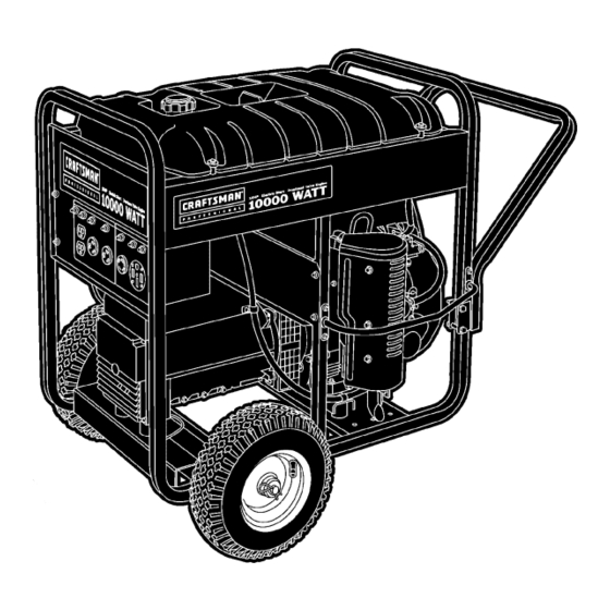
Owner's Manual
120/240 Volt
Electric Start
10,000 Watt
AC GENERATOR
Model No. 580.328300
Generator
Customer Helpline
1 - 8 0 0 - 2 2 2 - 3 1 3 6
HOURS: Mon. - Fri. 8 a.m. to 5 p.m. (CT)
CAUTION:
Before using this product, read this
manual and follow all its Safety Rules
and Operating Instructions.
Sears, Roebuck and Co., Hoffman Estates, IL 60179
Visit our Craftsman website: www.sears.com/craftsman
Part No. B4419 Draft 1 (6/14/2000) Printed in the U.S.A.
• Safety
• Assembly
• Operation
• Maintenance
• Parts
• Español
Advertisement
Chapters
Table of Contents

Related Manuals for Craftsman 580.328300


Summary of Contents for Craftsman 580.328300
- Page 1 Safety Rules • Operation and Operating Instructions. • Maintenance • Parts Sears, Roebuck and Co., Hoffman Estates, IL 60179 • Español Visit our Craftsman website: www.sears.com/craftsman Part No. B4419 Draft 1 (6/14/2000) Printed in the U.S.A.
-
Page 2: Table Of Contents
TABLE OF CONTENTS Warranty ........2 Troubleshooting ......17 Safety Rules . -
Page 3: Safety Rules
SAFETY RULES • Never operate the generator: WARNING: in rain; in any enclosed compartment; when connected electrical devices overheat; if electrical The engine exhaust from this product contains output is lost; if engine or generator sparks; if flame chemicals known to the State of California to cause or smoke is observed while unit is running;... -
Page 4: Assembly
ASSEMBLY Your generator requires some assembly and is ready CHECK BATTERY / ATTACH for use after it has been properly serviced with the NEGATIVE BATTERY WIRE recommended oil and fuel. The battery on the generator is fully charged, sealed If you have any problems with the assembly of and pre-installed except for the negative (black) your generator, please call the generator helpline battery cable. - Page 5 WHEEL KIT INSTALLATION NOTE: Be sure to install the wheel with the air pressure valve outboard. To install your wheel kit, you will need the following 5. Install other wheel in the same manner. tools: 6. Secure the vibration mount on the support leg with •...
-
Page 6: Operation
OPERATION KNOW YOUR GENERATOR Read the owner’s manual and safety rules before operating your generator. Compare the illustrations with your generator to familiarize yourself with the locations of various controls and adjustments. Save this manual for future reference. Fuel Shut Off Valve Fuel Tank Air Filter (on top of engine) - Page 7 BEFORE STARTING THE GENERATOR Add Engine Oil NOTE: A 20 hour break–in period is required. Replace engine oil and oil filter after the first 20 hours. Do Not use synthetic oil during the break–in period. NOTE: When adding oil to the engine crankcase in the future, use only high quality detergent oil rated with API service classification SF or higher.
- Page 8 HOW TO USE YOUR GENERATOR TO START THE ENGINE If you have any problems operating your generator, WARNING! Never start or stop engine with please call the generator helpline at 1-800-222-3136. electrical devices plugged into the panel Grounding The Generator receptacles and turned on.
- Page 9 NOTE: If engine fails to start, set the key to the “Run” • Set the key switch to the “Stop” position after position and wait for about 10 seconds before retrying. stopping the engine. Failure to put the key switch into the “Stop” position will deplete the IMPORTANT: Never turn the key switch to the “Start”...
- Page 10 RECEPTACLES Use this receptacle to operate 120 Volt AC, 60 Hz, single phase loads requiring up to 2,400 watts (2.4 120 Volt AC, 20 Amp, Duplex Receptacle kW) of power at 20 Amps. The outlet is protected by a 20 Amp push-to-reset circuit breaker. This is a 120 Volt AC outlet, consisting of a pair of receptacles protected against overload by a 20 Amp 120 Volt AC, 30 Amp Receptacle...
- Page 11 120/240 Volt AC, 30 Amp Receptacle 120/240 Volt AC, 50 Amp Receptacle Use a NEMA L14-30 plug with this receptacle. Use a NEMA 14–50 plug with this receptacle. Connect Connect a suitable 4-wire grounded cord set to the a 4-wire cord set rated for 250 Volts AC at 50 Amps to plug and to the desired load.
- Page 12 DON’T OVERLOAD THE • Some electric motors, such as induction types, require about three times more watts of power for GENERATOR starting than for running. This surge of power lasts only a few seconds when starting such motors. Overloading a generator in excess of its rated wattage Make sure you allow for this high starting wattage capacity can result in damage to the generator and to when selecting electrical devices to connect to your...
-
Page 13: Maintenance
MAINTENANCE MAINTENANCE SCHEDULE The following chart is based on normal engine operation. Follow the hourly or calendar intervals, whichever occurs first. More frequent service is required when operating in extremely dusty or heavy load conditions. Every 8 hours Every 50 Every 200 Every 500 Every 1000... -
Page 14: Product Specifications
PRODUCT SPECIFICATIONS Check the cleanliness of the generator frequently and clean when dust, dirt, oil, moisture or other foreign Engine Specifications substances are visible on its exterior surface. Type ..........Air Cooled, 4 stroke, CAUTION! Never insert any object or tool V-Twin, Horizontal through the air cooling slots, even if the engine Shaft, OHV gasoline... - Page 15 4. Coat the o-ring of a new filter with engine oil. Turn Paper Element the new filter clockwise until the gasket contacts • Clean by tapping gently to remove dirt and blow off the filter adapter, then tighten an additional dust.
-
Page 16: Storage
STORAGE GENERAL • Cover spark plug holes with rag. Crank the engine for 2-3 seconds and reinstall the spark plugs. The generator should be started at least once every Do Not connect spark plug wires. seven days and allowed to run at least 30 minutes. If •... -
Page 17: Troubleshooting
TROUBLESHOOTING Problem Cause Solution 1. Circuit breaker is open. 1. Reset circuit breaker. 2. Poor connection or defective 2. Check and repair. Engine is running, but no AC cord set. output is available. 3. Connected device is bad. 3. Connect another device that is in good condition. -
Page 18: Schematic
SCHEMATIC... -
Page 19: Wiring Diagram
WIRING DIAGRAM... -
Page 20: Replacement Parts
PARTS LIST Craftsman 10,000 Watt Generator 580.328300 Main Unit... - Page 21 Craftsman 10,000 Watt Generator 580.328300 Main Unit Item Part # Qty Description Item Part # Qty Description BB4509 SHIELD, Heat BB4682 BRACKET, Ignition Switch B77304 SUPPORT, Engine B96925 BRACKET, Battery Tie Down BB4811 SHIELD, Heat 96924 J-BOLT, M8 - 1.25...
- Page 22 Sincro Alternator Model EK–10 Item Part # Qty Description B4906 SHIELD, Front B4907 GRID, Front B4908 BOLT, Shaft Stay B4909 STAY BOLT, M8 x 30 B4910 ASSEMBLY, Housing B4911 B4912 COVER, Blind End B4913 COVER, Top Black B4914 CAPACITOR, 25mF 450V B4915 BEARING, 62052RS C3 B4916...
- Page 23 Craftsman 10,000 Watt Generator 580.328300 Control Panel Item Part # Qty Description Item Part # Qty Description BB4504 PANEL, Control 80077 PPHMS, M4 x 20mm 23897 FLAT WASHER, #10 - M5 92953 BLOCK, 50 Amp, 3 - Terminal 91526 PPHMS, M5 - .08 x 12mm...
- Page 24 Craftsman 10,000 Watt Generator 580.328300 Wheel Kit Item Part # Qty Description 93393B HANDLE 39287 HHCS, M8 - 1.25 x 45 52858 NUT, Locking M8 - 1.25 93394 LEG, Mounting Support 27007 MOUNT, Vibration 22145 FLAT WASHER, 5/16 - M8 42909 HHCS, M8 - 1.25 x 30...
- Page 25 Robin 18 HP Engine, Model EH63 Item Part # Qty Description Item Part # Qty Description 263-33001-03 INTAKE MANIFOLD 014-90800-21 ADJUSTING SCREW 263-31A01-03 CAMSHAFT 017-00800-90 020-02000-10 WASHER 246-35201-03 GASKET, muffler 246-33301-03 TAPPET 002-38080-00 FLANGE NUT 263-33401-03 INTAKE VALVE 263-32601-00 AIR CLEANER ASSY (Includes 263-33501-03 EXHAUST VALVE items 18 - 21)
- Page 26 Robin 18 HP Engine, Model EH63...
- Page 27 Robin 18 HP Engine, Model EH63 Item Part # Qty Description 263-10101-01 CRANKCASE, compl. (Includes items 2 thru 9) 263-15801-03 MAIN BEARING 005-26081-80 DOWEL PIN 142-55601-03 PIPE 159-65401-03 PIPE (PULSE) 212-15008-13 BLIND PLUG 044-00800-10 OIL SEAL 263-15901-03 UNION 045-01200-10 STEEL BALL 248-76301-01 SWITCH OIL PRESSURE 263-11102-01...
- Page 28 Robin 18 HP Engine, Model EH63 Item Part # Qty Description Item Part # Qty Description 263-46001-03 Choke Control Link 263-43311-A3 SPEED CONTROL LEVER 263-46011-01 Choke Control Rod 263-45021-A2 BRACKET, Speed Control 263-43901-01 Choke knob 261-43901-03 CLAMP 263-46010-03 Choke Knob Clamp 005-11060-00 SNAP PIN 261-45201-03...
- Page 29 Robin 18 HP Engine, Model EH63 Item Part # Qty Description 263-51101-02 BLOWER HOUSING UNIT 263-52601-01 CYLINDER BAFFLE I COMPL. 263-52701-01 CYLINDER BAFFLE 2 COMPL. 263-52801-03 CYLINDER BAFFLE 3 263-52911-A2 CYLINDER BAFFLE 4 UNIT 011-00600-20 FLANGE BOLT 263-92001-03 LABEL (WARNING) 263-95201-03 LABEL (EMISSION CONTROL) 263-54101-02...
- Page 30 Robin 18 HP Engine, Model EH63...
- Page 31 Robin 18 HP Engine, Model EH63 Item Part # Qty Description 263-63901-03 INNER ROTOR 263-63902-03 OUTER ROTOR 263-64301-02 OIL PUMP FILTER UNIT 263-64001-01 OIL PUMP COVER, compl. (Includes item 5) 044-03500-90 OIL SEAL X24-08900-20 O-RING 263-65001-13 PLUG, oil relief 003-70140-00 GASKET, aluminum 248-65601-03 SPRING, relief valve...
- Page 32 Robin 18 HP Engine, Model EH63...
- Page 33 Robin 18 HP Engine, Model EH63 Item Part # Qty Description 258-62545-08 GASKET, air horn BODY, Air Horn 263-62524-08 LEVER ASSY, choke 258-62551-08 RING, choke lever 263-62445-08 SPRING, choke 258-62553-08 COLLAR, choke 258-62554-08 FILTER, choke shaft 263-62520-08 SHAFT ASSY, choke 258-62525-08 CHOKE VALVE 258-62555-08...
- Page 34 Robin 18 HP Engine, Model EH63 Item Part # Qty Description 263-21201-01 CRANKSHAFT, Taper 2.25/12 (SAE-WG) 263-22501-00 CONNECTING ROD ASSY (Includes item 3) 246-23001-03 CONNECTING ROD BOLT 263-23401-03 PISTON 263-23301-03 PISTON PIN 263-23501-07 PISTON RING SET 056-52100-20 CLIP 263-25001-03 SPACER, t = 0.6 or 263-25002-03 SPACER, t = 0.8 or 263-25003-03...
- Page 35 Robin 18 HP Engine, Model EH63 Item Part # Qty Description 263-77202-01 FLYWHEEL, compl. 263-78201-01 IGNITION COIL, compl. 246-79501-03 GROMMET 263-71001-03 RING GEAR 263-70502-A0 STARTING MOTOR ASSY 263-73016-01 WIRE 4, compl. 263-73017-01 WIRE 5, compl. 065-01404-80 SPARK PLUG, compl. 065-50001-40 SPARK PLUG CAP 065-90000-10 PLUG TERMINAL...
- Page 36 Robin 18 HP Engine, Model EH63 Item Part# Qty Description 017-00800-30 Flanged Nut (M8) 263-35201-A1 Gasket 263-34101-A1 Manifold 263-34211-01 Muffler Cover 011-00600-10 Flange Bolt 263-30201-01 Muffler 263-37301-A1 Deflector Ass’y 263-37011-A1 Bracket 001-11081-60 Bolt W/ Lockwasher (M8x16) 001-04085-05 Flange Bolt (M8 x 50 263-37321-A2 Spark Arrester...
- Page 37 Robin 18 HP Engine, Model EH63 Item Part # Qty Description 263-70502-A0 STARTING MOTOR ASSY (Includes items 1 thru 21) 263-70510-08 ARMATURE ASSY 263-70550-08 THRUST WASHER KIT 210-70534-08 PINION STOPPER SET 255-70580-08 YOKE ASSY 263-70505-08 REAR COVER ASSY (Includes item 7) 255-70531-08 BRUSH HOLDER ASSY (Includes items 9 thru 11) 228-70514-08...
-
Page 38: Emissions Warranty
EMISSION CONTROL SYSTEM WARRANTY YOUR WARRANTY RIGHTS AND WHAT IS COVERED OBLIGATIONS Repair or Replacement of Parts The California Air Resources Board ("CARB") and • Repair or replacement of any warranted part will be Sears Roebuck and Co., USA, are pleased to explain performed at no charge to the owner at an the Emission Control System Warranty on your model approved Sears service center. - Page 39 Emission Control Warranty Parts List Maintenance Statements 1. Fuel Metering System It is your responsibility to have all scheduled inspection and maintenance services performed at the Carburetor and internal parts times recommended in the 1998 and later owner’s Choke system manual and to retain proof that inspection and Fuel strainer, if applicable maintenance service are performed at the times when...
-
Page 40: Español
TABLA DE CONTENIDOS Garantía ....... . 40 Especificaciones del Producto ....52 Reglas de Seguridad . -
Page 41: Reglas De Seguridad
REGLAS DE SEGURIDAD recubrimiento, etc. Nunca permita que personas no ADVERTENCIA: calificadas operen o proporcionen servicio al generador. • Nunca manipule dispositivos o cordones eléctricos El escape del motor de este producto contiene elementos cuando se encuentre parado en agua, descalzo o con los químicos, los cuales son reconocidos en el Estado de pies o las manos mojadas. -
Page 42: Montaje
MONTAJE Su generador requiere de cierto ensamble y estará listo REVISE LA BATERIA / CONECTE EL para ser usado después de haberle dado un servicio ALAMBRE NEGATIVO DE LA adecuado con el aceite y el combustible recomendados. BATERIA Si tiene problemas con el montaje de su generador, por favor llame a la Línea de Ayuda del Generador al La batería del generador se encuentra completamente 1-800-222-3136. - Page 43 INSTALACION DEL JUEGO DE NOTA: Asegúrese de instalar la rueda con la parte levantada de la maza hacia adentro. RUEDAS 5. Instale la otra rueda de la misma forma. 6. Asegure el montaje antivibratorio a la pata de soporte Para instalar su juego de ruedas, necesitará las con la tuerca de sujeción y el tornillo prisionero largo de siguientes herramientas: 30 mm.
-
Page 44: Funcionamiento
FUNCIONAMIENTO CONOZCA SU GENERADOR Lea este manual del propietario y las reglas de seguridad antes de operar su generador. Compare las ilustraciones con su generador para familiarizarse con la ubicación de los diferentes controles y ajustes. Válvula de Corte de Combustible Tanque de Combustible Filtro de Aire Cortacircuitos... - Page 45 ANTES DE DARLE ARRANQUE AL • En adelante, revise el nivel de aceite del motor antes de cada arranque. Vuelva a depositar aceite si su nivel se GENERADOR encuentra por debajo de la línea inferior de la varilla de medición. Añada Aceite al Motor NOTA: El motor requiere de un período de despegue de Medidor de Aceite...
- Page 46 COMO USAR SU GENERADOR PARA DARLE ARRANQUE AL MOTOR Si tiene problemas operando su generador, por favor llame a la línea de ayuda para generadores al 1-800-222-3136. ¡ADVERTENCIA! Nunca arranque o detenga el Conexión a Tierra del Generador motor teniendo dispositivos eléctricos conectados y El Código Eléctrico Nacional exige que el bastidor y las encendidos en los tomacorrientes del panel.
- Page 47 IMPORTANTE: No active el arranque eléctrico de forma • Deje que el motor funcione sin cargas por 30 segundos continua por más de 5 segundos, incluso si el motor no para estabilizar las temperaturas internas del motor y el enciende. El viraje prolongado puede dañar el motor del generador.
- Page 48 TOMACORRIENTES Utilice este tomacorriente para operar cargas de 120 Voltios AC, 60 Hz, monofásicas que requieran hasta 2,400 vatios Tomacorriente Doble de 120 Voltios AC, (2.4 kW) de potencia a 20 Amperios. La toma está protegida 20 Amperios por un cortacircuito con dispositivo de reposición de 20 Amperios.
- Page 49 Tomacorriente de 120/240 Voltios AC, Tomacorriente de 120/240 Voltios AC, 30 Amperios 50 Amperios Use un enchufe tipo NEMA L14-30 con este tomacorriente. Utilice un enchufe NEMA 14-50 con este tomacorriente. Conecte al enchufe y a la carga que desee un juego de Conecte al enchufe un juego de cordones de 4 alambres cordones de 4 alambres con conexión a tierra.
- Page 50 NO SOBRECARGUE EL • Algunos motores eléctricos, tal como tipos de inducción, requieren acerca de tres vez más vatios del poder para GENERADOR comenzar que para correr. Esta onda irruptiva de poder dura tan solo unos segundos durante el arranque de Sobrecargar el generador más allá...
-
Page 51: Mantenimiento
MANTENIMIENTO PROGRAMA DE MANTENIMIENTO La siguiente tabla está basada en el funcionamiento normal del motor. Siga los intervalos horarios o de calendario, lo que ocurra primero. Se requiere de servicio con mayor frecuencia cuando opere la unidad en condiciones con exceso de polvo o cargas pesadas. -
Page 52: Especificaciones Del Producto
ESPECIFICACIONES DEL PRODUCTO Revise frecuentemente la limpieza del generador y límpielo cuando elementos como polvo, suciedad, aceite, humedad o Especificaciones del Motor substancias extrañas sean visibles sobre su superficie exterior. Tipo ......Motor a gasolina OHV Enfriado a ¡PRECAUCION! Nunca inserte objetos o... - Page 53 Siga las siguientes instrucciones para cambiar el aceite Limpieza de la Espuma de Uretano mientras el motor se encuentre caliente: • Lave y limpie la espuma de uretano en kerosene. Sature 1. Limpie el área alrededor del tapón para drenaje de la espuma en una mezcla de 3 partes de kerosene y aceite, retire el tapón y drene el aceite por completo en 1 parte de aceite de motor, después exprímala para...
-
Page 54: Almacenamiento
ALMACENAMIENTO GENERALIDADES • Cubra los orificios de la bujías con un trapo. Haga girar el motor por 2-3 segundos y vuelva a instalar la bujías. No El generador deberá ser encendido al menos una vez cada conecte los alambres de las bujías. siete días y deberá... -
Page 55: Reparacion De Averías
DIAGNOSTICO Y REPARACION DE AVERIAS Problema Causa Solución Cortacircuitos abierto. Reajuste el cortacircuito. Mala conexión o juego de cordones Revise y repare. defectuoso. El motor está funcionando pero El dispositivo conectado está en mal Conecte otro dispositivo que esté en no existe salida de AC disponible. -
Page 56: Garantía De Emisiones
GARANTÍA DEL SISTEMA DE CONTROL DE EMISIÓN SUS DERECHOS DE GARANTÍA Y Período de Cobertura OBLIGACIONES Sears garantiza al propietario original y a cada comprador subsecuente que el motor se encuentra libre de defectos en El Comité de Recursos del Aire de California (The California materiales y mano de obra, los cuales pueden causar la Air Resources Board - "CARB"), y Sears Roebuck and Co., falla de la parte garantizada por un periodo de dos años. - Page 57 Dónde Obtener el Servicio de Garantía Declaración de Mantenimiento Los servicios de garantía o de reparación deberían ser Es su responsabilidad llevar a cabo todas las provistos en todos los centros de servicios autorizados de inspecciones y servicios de mantenimientos planificados Sears.
- Page 58 NOTAS...
- Page 59 NOTAS...
- Page 60 For in-home major brand repair service: Call 24 hours a day, 7 days a week 1-800-4-MY-HOME (1-800-469-4663) Para pedir servicio de reparación a domicilio - 1-800-676-5811 In Canada for all your service and parts needs call - 1-800-665-4455 Au Canada por tout le service ou les pièces For the repair or replacement parts you need: Call 7 am - 7 pm, 7 days a week 1-800-366-PART...
Need help?
Do you have a question about the 580.328300 and is the answer not in the manual?
Questions and answers