
Related Manuals for Hunter ICD-HP


Summary of Contents for Hunter ICD-HP
- Page 1 ICD‐HP Handheld Programmer for Hunter ICD Decoders Owner’s Manual and Operating Instructions 1 ...
-
Page 2: Table Of Contents
Introduction ..................................... 3 ICD‐HP Components ................................ 5 Installing the Batteries .............................. 7 Keypad Functions ................................ 8 Cable and Lead Connections ............................ 9 Connecting to a Decoder .............................. 9 Operations ..................................... 1 1 Main Menu & Navigation .............................. 1 1 ICD‐HP Set‐up ................................. 1 2 Decoder Programming Menu ............................ 1 3 ... -
Page 3: Introduction
Diagnostics .................................. 2 5 Troubleshooting .................................. 2 7 Specifications .................................. 2 9 FCC Notice .................................... 3 0 Industry Canada Notice ................................ 3 1 CE & AUSTRALIA NOTICE ................................ 3 1 Introduction The ICD‐HP Handheld Programmer is an innovative setup, programming, and diagnostic tool for Hunter ICD series decoder products. This instrument can operate and program ICD decoders via wireless induction, through the base of the decoder, with a special programming cup. This allows access to installed decoders, without removing waterproof wire connectors. ICD‐HP can also be used for initial setup of new decoders. The included power leads will power a decoder for programming purposes, for installation later. ICD‐HP can be used for diagnostic operation and testing of installed decoders, solenoids, and even sensors. 3 ... - Page 4 ICD‐HP can enable new programming options for ICD decoders. It can program any station numbers in any order within a multi‐station decoder, and can “skip” stations to reserve them for future use. 4 ...
-
Page 5: Icd-Hp Components
ICDHP Components ICD‐HP is packaged with required accessories. 5 ... - Page 6 Item Part Description ---- ICD-HP Programmer The Programming Cable is NOT a standard BNC connector cable, and cannot be replaced with a standard coaxial BNC cable. 205700 Programming Cup This item is unique to the ICD‐HP programmer. 180504 Programming Cable 6’/2m with connectors Do not attempt to use the ICD‐HP programming cable for any other purpose! 180508 Red and Blue 6’/2m leads ---- Carrying Case ---- 4 x AA batteries 6 ...
-
Page 7: Installing The Batteries
Installing the Batteries The ICD‐HP programmer operates with 4 x AA batteries. The batteries supplied are not rechargeable! To install batteries: Remove cables and connectors from end of ICD‐HP. Pry the yellow flexible yellow boot off the ICD‐HP. Turn the ICD‐HP over, and remove the 2 screws securing the battery compartment cover with a small screwdriver (either standard or Philips). Insert 4 fresh AA batteries as shown, observing polarity. Replace cover with screws and secure. Replace yellow boot. 7 ... -
Page 8: Keypad Functions
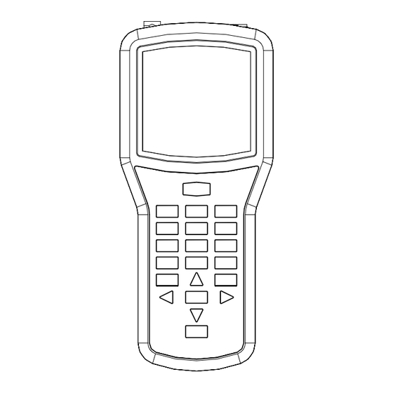
Keypad Functions 1. Power button. 2. Number buttons, used to enter station numbers and other numeric data. 3. Back button. Returns to previous menu. 4. Plus and Minus (+/‐) buttons. Used to change station numbers, and also to turn stations On (+) and Off (‐). 8 5. Arrow buttons. Used to navigate within screens, move pointers, or change outputs on multi‐station decoders. 6. Enter. Used mostly to retry certain functions. 7. Question/Info. Used to switch pages, in some screens. Also used to enter ICD‐HP flash mode. 8. Next button. Used to select a menu item and go to the next level. Also used to execute certain commands. 8 ... -
Page 9: Cable And Lead Connections
Cable and Lead Connections Red and Blue Leads: Connect the straight connectors by pushing all the Lead way into the appropriately colored plugs. Programming Cable: Connect either end of the supplied cable to the connector on the ICD‐HP. Align connector slots with female connector on programmer, push straight in, and turn 90 degrees until the connector locks into place. Connect the other end of the Programming Cable to the Programming Cup in the same way. Blue Programming Lead Connecting to a Decoder Cable The ICD‐HP programmer works with Hunter ICD and later decoders. The ICD‐HP programming cup communicates with decoders through wireless induction. The bottom end of the decoder (opposite the end with the wires) is the receiver area for the signals from the programming cup. The entire inside of the cup is within the wireless range, and it is not necessary to press decoders firmly in place, as long as they are within the cup. The programming cup 9 ... - Page 10 does have pockets for the two different sizes of decoder, and these will help hold the cup and decoder together firmly in field applications. Bench Mode: If the decoder is uninstalled, and not connected to the two‐wire path: Install the red and blue wire leads for the ICD‐HP. Connect the programming cup to the ICD‐HP. Clip the red and blue leads to the decoder red and blue leads. Place the decoder in the programming cup. Field Mode: If the decoder is installed in the two‐wire path, it is not necessary to disconnect any decoder wiring. Connect the programming cup to the ICD‐HP with the programming cable. Wipe mud and dirt off the decoder to prevent wear on the programming cup and interference with the signal. 10 ...
-
Page 11: Operations
Seat the programming cup over the decoder. The bottom of the decoder (the end with no wires) should be within the programming cup. Verify that the two‐wire path is connected to the controller, and that controller power is on. The decoder will be powered over the two‐wire path, and the red and blue ICD‐HP leads will not be necessary. Protect the ICD‐HP from sprinkler spray and other water sources! Operations Turn the programmer on with the power button. The logo will appear, and change to the Main Menu in a few seconds. Main Menu & Navigation For the first use, or to change general settings, select ICD‐HP Setup. Most menu selections throughout ICD‐HP operate with the same buttons. Use the arrow keys to navigate around the screens. Use the + and – buttons to change the choices in settings. Use the Next button to select an option, and go to the next screen. Use the Back button to exit and return to the previous level. In some selections, the Enter button is used to make selections. 11 ... -
Page 12: Icd-Hp Set
ICD‐HP Set‐up LCD Settings: Adjust screen appearance with Contrast, Backlight, and Backlight Timeout controls. Use the arrow buttons to move to the item you wish to change, and press the + or – buttons to adjust the settings. Increasing the contrast and backlight can improve visibility in low light conditions, but will also consume batteries more quickly. The backlight will turn off automatically after a period of no use. The time is selectable under Backlight Timeout controls, or the backlight can be turned off to preserve battery life. Set Languages: Select operating system language of your programmer. Use the up/down arrow keys to set the pointer to your selection. Use the Next button to make the selection, and the display will show the selection. Press the Back button to exit. Set Units of Measure: Change between English and Metric readings (GPM or LPM). Use the up/down arrow keys to set the pointer to your selection. Use the Next button to make the selection, and the display will show the selection. Press the Back button to exit. 12 ... -
Page 13: Decoder Programming Menu
Current Dec Versions: Shows the current versions of decoder firmware loaded into ICD‐HP. If you flash update a decoder’s operating system, this is the version that will be loaded. DECODER PROGRAMMING ----------MENU--------- Get Decoder Info Decoder Programming Menu Program Decoder Install a decoder with either method in “Connecting to a Decoder” section. Get Decoder Status From the Main Menu, use the arrow keys to point to Decoder Programming, and press the Next button. The Decoder Programming Menu will appear. Use the arrows to move the pointer to any function, and press Next to select it. Get Decoder Info will check the decoder and display its current settings. It will DECODER INFO not change any of the settings in the decoder. It can be used to identify the ---------------------- station number(s) and other settings of any ICD or later decoder. Dec Type: 2-Station Output #: Dec Type shows if the decoder is a station decoder and the number of Station #: stations, or Pump decoder, or Sensor decoder. Serial #: ######## ◄/►Change OUTPUT # Press ? For More DECODER INFO ----------------------... - Page 14 Output #: If the decoder is a multi‐station decoder, the display only shows the station address of one output at a time. Each color‐coded pair of wires from the decoder is a different output. Press the left and right arrow buttons to move through the different outputs, and view the station numbers for each output. Decoder Info screens multi‐page screens. Press the ? button for More. The second page will show the Power Factor, Inrush setting, and Version of the decoder firmware. Press ? again to return to the first page. Serial numbers are not used to address decoders, except in older Hunter decoder controllers (IDS, Genesis and VSX “Viking” decoder systems). Serial numbers cannot be changed. 14 ...
- Page 15 Program Decoder will enter the station addresses and other settings of the decoder. Move the pointer with the arrow buttons at the Main Menu screen to PROGRAM A DECODER Program Decoder and press Next . ---------------------- Dec Type: 6-Station The ICD‐HP will check for a decoder. If successful, it will display the Type, Pwr Factor: Power Factor, and Inrush information for the decoder after a few seconds. Inrush: Type: Press the + and – buttons to change the decoder type. It is possible to change a station decoder to Pump, to assign it to one of the P/MV Press To Continue (Pump/Master Valve) outputs for the controller. It is best to use a single‐ station decoder for a P/MV output. If a multi‐station decoder is set to Type -PROGRAM A DECODER-- Pump, the other outputs can no longer be used, and will be wasted. Output 1: Sta-027 Output 2: Sta-000 If the Type shown is “Sensor”, the ICD‐HP is reading a Sensor Decoder and the Output 3: Sta-000 Type cannot be changed. Output 4: Sta-000 Output 5: Sta-000...
- Page 16 Inrush: This can change the inrush timing for the station or relay when first turning on. Default setting is 3, and this rarely needs to be changed. Consult Hunter Technical Support before changing the Inrush value. Press Next to continue. Assign Station Numbers: The next screen will show the station number assigned to each decoder output. The number of outputs is based on the decoder’s size. A single station decoder (ICD‐100) will only show one output. A two‐station decoder (ICD‐200) will show two output lines, etc. Use the up and down arrows to move the pointer to each output. Use the number keys to type the controller station number you wish to assign to each output. Or, use the + and – keys to raise and lower the station numbers. -PROGRAM A DECODER-- Output 1: Sta-001 If you have already assigned a station number to an output, using the + and – Output 2: Sta-002 buttons to change another output will skip over any station number that has Duplicate Sta-003 already been assigned. Duplicate Sta-003 Example: Output 1 is assigned Sta‐007. When setting Output 2, using the +/‐ Press To Program buttons will skip 007 and move directly from 006 to 008. Flashing “Duplicate” shows duplicate station If numbers are entered directly from the keypad, it may temporarily permit a numbers‐ change address before duplicate, but this will not be sent to the decoder. If a duplicate station programming. number is entered in a multi‐station decoder, and the Next button is 16 ...
- Page 17 pressed, the ICD‐HP will refuse to send the program until the duplicate numbers have been changed. The outputs with duplicate numbers will flash “Duplicate”, alternating with the output numbers. Pump: If the Type was changed to Pump (instead of a station decoder), only Output 1 will be shown. Use + and – to change between P/MV‐1 and P/MV‐2. (P/MV = Pump/Master Valve). Programming: When all settings are made, and outputs are numbered (see Important Notes section), press the Next button to send the station numbers to the decoder. The display will show “Programming…” for a short time. If successful, “Programming Complete” will appear after the program has been sent. Decoder comm failed: This message indicates that the programming was not successful. Most likely causes are the connections, or the decoder power. Check power leads to the decoder, programming cup cable connections, and verify there is power on the two‐wire path from the controller (if programming in line). Turn Line Power Off, and Back On: After programming or re‐programming installed decoders, the two‐wire path power must be turned off for 15 seconds, and then back on, for the programming to take effect in the field. The station numbers will be in the decoder’s memory, but the power must be cycled (off/on) to take effect. You can turn off power to the controller, or remove the ADM99 output module from the controller, and then plug it back in after 15 seconds. 17 ...
- Page 18 Important Notes: Outputs may be assigned from 000 to 500. Do not assign a station number higher than the capacity of your controller, or it will not operate! (Example: ACC99D has 99 station capacity. Do not program a station number higher than 99). The ICD‐ HP does not know the capacity of your controller. Reserved Stations: It is possible to assign “000” to a decoder output with the ICD‐HP. This output will not be used. However, it may be programmed at a later date, to add a new station to a multi‐station decoder. -PROGRAM A DECODER-- Output 1: Sta-001 For example, a six‐station decoder could have output #6 (or any other Output 2: Sta-032 outputs) set to station 000. The 000 outputs would not be operational, but Output 3: Sta-025 could be reserved for future additions. Then the new station number could Output 4: Sta-081 Output 5: Sta-014 be assigned to the reserved 000 output with the ICD‐HP. Output 6: Sta-000 Press To Program Do not assign a station 000 unless you wish to skip a station, or reserve one for future expansion. Station number 000 cannot be turned on by a Sample ICD‐600 display with random station controller! numbers and Output 6 held in reserve (000). Stations in Random Order: It is possible to assign any valid station numbers in any order. The ICD‐HP can enter any ...
- Page 19 Do not assign duplicate addresses! No decoder controller should have duplicate station numbers, anywhere within the entire system. (This does not apply to station 000, however.) The ICD‐HP will not allow duplicate station numbers within a single decoder, but it cannot detect duplicates elsewhere in the system. Sensor Decoder Programming (ICD‐SEN) If the decoder in the programming cup is an ICD‐SEN sensor decoder, only PROGRAM A DECODER the address can be set. The Type will be Sensor, and this cannot be ---------------------- changed when a sensor decoder is found. Dec Type: Sensor Address: Choose an address between 1‐5 with the + or – buttons, and press Next to send to the sensor decoder. Turn Line Power Off, and Back On: After programming or re‐programming installed decoders, the two‐wire path power must be turned off for 15 seconds, and then back on, for the programming to take effect in the field. Other Sensor Decoder set up options are made at the controller, and not from the ICD‐HP. Consult controller and/or sensor decoder documentation for complete setup instructions. Get Decoder Status 19 ...
- Page 20 Connect to any decoder to view status, for identification and diagnostics. This can be used with either installed decoders, or disconnected decoders that are powered through the ICD‐HP power leads. From the Main Menu, select Decoder Programming with the Next button. Move the pointer with the up/down arrows to Get Decoder Status, and press Next again to select. The ICD‐HP will attempt to communicate with the decoder. When a decoder is found, the status will be displayed. DECODER STATUS ---------------------- Station Decoders: If the decoder is a Station Output decoder, the display will Dec State: Normal show the following information. Current: 167mA Dec State: Can be Normal, Fault, or Damaged. Output #: 1 2 3 4 5 6 Solenoid: Y Y Y Y Y N Active : Y Y Y Y N N Normal: Decoder is responding correctly. ...
- Page 21 Decoder comm failed: This may indicate a complete decoder failure, OR the decoder may not be connected or powered properly. Verify ALL connections: ICD‐HP to programming cup (both ends) and decoder power. If the decoder is connected in the two‐wire path but the controller power is Off, decoder will not respond. If decoder and ICD‐HP are connected correctly, and decoder has power, and Decoder comm failed message appears, decoder is likely defective. Current: Displays electrical current draw of decoder in milliamps. Standby range is approximately 3‐5ma. When decoder is active, this value will be higher, depending on number and type of devices connected to decoder output. Total current on a decoder cannot exceed 1000ma. The current display does not change in real time. If a station is started or stopped, run the diagnostic Get Decoder Status again to see the new current draw. Output: The output matrix shows the status of each output of the decoder. The display will show the number of outputs for the size of decoder detected (a single station decoder will only have 1 output). Solenoid: Shows whether a solenoid or similar device is detected on the output (Y=Yes, N=No). The Solenoid status may not change until power has been cycled off/on to the decoder, if a solenoid has just been added to the decoder. Turn off either the controller, or remove the ADM99 decoder output module from the controller, for approximately 15 seconds, and then turn the power back on (or replace the ADM99). Solenoid status will be updated. 21 ...
- Page 22 Active: Shows whether the output is currently turned on (Y=Yes, N=No). Sensor Decoders: If the decoder found during Get Decoder Status is a Sensor Decoder, the display will show the status of each sensor input to the decoder’s Ports, on individual screens. SENSOR STATUS Use the left and right arrows to see each Port (A and B) individually. ---------------------- Port A Type: Clik Clik sensors: The display will show the current state of the Clik input as State: Closed Closed (normal) or Open (alarmed). Flow sensors: The display will show the type of flow sensor (set from the controller), the size or K‐Factor and Offset, and the current actual flow in ◄/► To Change Port GPM or LPM (depending on Unit of Measurement settings). The ICD‐HP is not used to set or change flow sensor settings. It shows what SENSOR STATUS the controller has sent to the sensor decoder, and displays the current flow. ---------------------- Port A Type: FLOW The flow sensor is always connected to Port A of the sensor decoder. Use Sensor: HFSFCT150 the left and right arrows to view Port B, which can be used for Clik sensor inputs. Flow Rate: xxxx.x GPM The flow reading will update changes in flow live, in the screen display, as ...
-
Page 23: Decoder Firmware
valves open and close. Decoder Firmware The decoder firmware menu checks, and has the ability to update, a decoder’s operating system (firmware). From the Main Menu, use the up/down arrows to move the pointer to Decoder Firmware, and press Next . The display will show two options, Get Decoder Ver and Update Dec Firmware. Get Decoder Ver: Move the pointer to Get Decoder Ver and press Next . This will check the decoder, and display the version number. Update Dec Firmware: Move the pointer to Update Dec Firmware and press DECODER UPDATE Next . This will display the “Latest Version” loaded into the ICD‐HP, and ---------------------- display it above the version found in the decoder. If the versions are different, Latest Firmware Version: #.##.### you have the option to load the latest version into the decoder. Attached Decoder Note: The “Latest Firmware Version” is loaded into the ICD‐HP operating Version: #.##.### system. This can be updated, if new firmware is released, by re‐flashing the Press To Continue ICD‐HP itself from a computer. The updates will contain both station decoder and sensor decoder firmware versions for the decoders. 23 ... - Page 24 If the version in the decoder is older than the version loaded into the ICD‐HP, DECODER UPDATE and you wish to update the decoder, press Next . This will show the version ---------------------- of the “bootloader” program, which actually loads the firmware into the decoder. Update Progress... Press Next again to continue, and the firmware update will begin. A status bar will show the progress of the download. It will take several minutes to update a decoder’s firmware. Do not disconnect the decoder during this update! The firmware update should always be allowed to complete, once it has begun. The update will not erase the decoder output station addresses. If the decoder is used as a Pump, this information will also be retained. DECODER UPDATE If the decoder is a Sensor Decoder, it will automatically receive the Sensor ---------------------- Decoder firmware, and the address and port settings will be retained. !Complete! Dec Type: X-Station Station #: A status screen will announce when the update is complete, and verify the Serial #: ######## new version number. Version: #.##.### 24 ...
-
Page 25: Diagnostics
Diagnostics The Diagnostics menu allows operation and test of decoder functions. TURN STATION ON/OFF From the Main Menu, move the pointer to Diagnostics and press Next . ---------------------- Output #: Turn Station On/Off: The ICD‐HP can turn individual station outputs on and Station #: off for diagnostic purposes. This function only works with decoders wired into Serial #: ######## State: the two‐wire path, and will not operate when powered by the leads from the ◄/► To Change Output # ICD‐HP! + On - Off Connect a decoder with the programming cup. Move the pointer to the Turn Station On/Off, and press Next . The ICD‐HP will first connect to the decoder, and display the first station output. If the decoder is a multi‐station decoder, use the left and right arrow buttons to move to the station to turn on or off. Press + to turn a station on. The station will run for approximately 1 minute if running alone, or 12 minutes if another station is running from the controller (see Important Note in this section). The State will change from Off to On after a few seconds. 25 ... - Page 26 If the station is connected to a pressurized valve, the water will turn on. Take care to keep the ICD‐HP out of the water from sprinklers. Press ‐ to turn a station off. The station will turn off and the State will change from On to Off after a few seconds. Important Note: The ICD‐HP cannot set a run time for a decoder activation. The ACC controller will send an Off command down the two‐wire path once per minute, when no stations are supposed to be running. If you turn a station on with the ICD‐HP, this controller command will turn that station back off, within a minute. If longer run times are required for diagnostic purposes, turn another decoder station on from the ACC controller, or with a remote control (ICR, ROAM, or Maintenance Radio). As long as this station is running from the controller, the “off “ command will not be sent every minute. If another station is running from the controller as described, and a station in the field is turned on with the ICD‐HP, it will run for approximately 12 minutes, or until it is turned off from the ICD‐HP. Get Decoder Status: This allows quick access to the same status matrix for outputs as the Get Decoder Status command from the Decoder Programming menu. This can be used to view the current draw of a solenoid after it has been turned on with the Turn Station On/Off command from the ICD‐HP. Turn the station or multiple stations on, then use Get Decoder Status to view the current draw on the decoder. 26 ...
-
Page 27: Troubleshooting
Troubleshooting PROBLEM CAUSES SOLUTIONS ICD‐HP will not communicate No power to decoder. Check controller power to two‐wire with decoder. path, or connect power leads to Decoder Programming cup disconnected. decoder. Batteries low. Check battery display or retry with USB power if available. Stations will not turn on. No solenoid connected. Check solenoid connections. Decoder is powered from ICD‐HP power Check two‐wire path and controller leads. power. 27 ... - Page 28 No power on two‐wire path. Master Valve not on (station solenoid is on, Start station with MV from controller but no water). or remote. Decoder will not respond after Stuck in bootloader mode. Repeat firmware update steps and firmware update. allow to complete. Poor battery life. Display backlight will reduce battery life. Reduce timer or turn off backlight display. 28 ...
-
Page 29: Specifications
Specifications Operating Specifications Height: 8.25”/21cm Station Number Range: 001 – 500 (blank outputs are set Width: 3.875”/9.8cm to “000”) Depth: 2.1875”/5.5cm Sensor Decoder Address Range: 001 ‐ 005 Dimensions, Programming Cup Max Cable length to Programming Cup: 6ft/2m Height: 2.375”/6cm Max Range of Induction Signal: 2”/5cm from bottom of Width: 2.375”/6cm programming cup. Depth: 2.625”/6.6cm Electrical Specifications Weight Battery Power: 4 x AA batteries ICD‐HP only: 1.4lbs/.63 kg Voltage Limit (red/blue leads): 60VAC, max Complete in Case: 4.8lbs/2.1kg Dimensions, ICD‐HP 29 ... -
Page 30: Fcc Notice
FCC Notice FCC ID: M3UICDHP This device complies with FCC rules Part 15. Operation is subject to the following two conditions: • This device may not cause harmful interference and • This device must accept any interference received, including interference that may cause undesired operation. This equipment has been tested and found to comply with the limits for class B digital devices, pursuant to part 15 of the FCC Rules. These limits are designed to provide reasonable protection against harmful interference in a residential installation. This equipment generates, uses, and can radiate radio frequency energy and if not installed and used in accordance with the instructions, may cause harmful interference to radio communications. However, there is no guarantee that interference will not occur in a particular installation. If this equipment does cause harmful interference to radio or television reception, which can be determined by turning the equipment on and off, the user is encouraged to try to correct the interference by one or more of the following measures: • Reorient or relocate the receiving antenna • Increase the separation between the equipment and the receiver • Connect the equipment to an outlet on a circuit different from that to which the receiver is connected • Consult the dealer or an experienced radio/TV technician for help The user is cautioned that changes and modification made to the equipment without the approval of the manufacturer could void the user’s authority to operate this equipment. 30 ... -
Page 31: Industry Canada Notice
Industry Canada Notice IC: 277A‐ICDHP Operation is subject to the following two conditions: This device may not cause harmful interference and This device must accept any interference received, including interference that may cause undesired operation. CE & AUSTRALIA NOTICE Hunter Industries hereby declares that this remote control device is in compliance with the essential requirements and other relevant provisions of Directive 1999/5/CE. Declaration of Conformity: We, Hunter Industries Incorporated, 1940 Diamond Street, San Marcos, CA 92078, declare under our own responsibility that the ICD Handheld Programmer, model ICD‐HP to which this declaration refers, conforms with the relevant standards: Emissions: ETSI EN 300 330‐2 V1.3.1 Immunity: ETSI EN 301 489‐1 V1.8.1 ETSI EN 300 330‐1 V1.3.1 ETSI EN 301 489‐3 V1.4.1 31 ...
Need help?
Do you have a question about the ICD-HP and is the answer not in the manual?
Questions and answers