Bowa ERGO 300 Operating Manual
Morcellator
Hide thumbs
Also See for ERGO 300:
- Information for use (52 pages) ,
- Instructions for use manual (39 pages)
Table of Contents
Advertisement
Quick Links
Advertisement
Table of Contents

Related Manuals for Bowa ERGO 300


Summary of Contents for Bowa ERGO 300
- Page 1 OPERATING MANUAL MORCELLATOR...
-
Page 3: Table Of Contents
General information Indications Principle Contraindications Medical application On receipt Scope of delivery, accessories and spare parts Technical Data «ERGO 300 - Morcellator» Ambient conditions Warranty coverage 1.10 Right to make technical changes reserved Explanation of symbols Safety information EMC Manufacturer’s Declaration of Conformity... -
Page 4: General Information
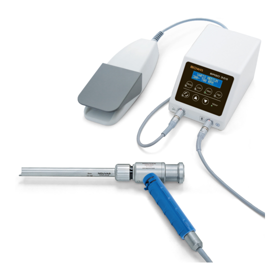
1.2 Principle The ERGO 300 - Morcellator is a control unit for the BOWA Morcellator for use in morcellation and extraction of tissue. A rotating cylindrical tube with a blade at the distal end is inserted through an abdominal cavity that has been enlarged by an Insufflator. -
Page 5: On Receipt
The shipping package must contain all parts listed in 1.6 Scope of delivery. • If any parts are damaged or missing, contact the BOWA agent from which the device was or- dered or BOWA. Immediate inspection of the ERGO 300 - Morcellator motor system (art. no. 905-000): 1. -
Page 6: Scope Of Delivery, Accessories And Spare Parts
Morcellator Motor cable 3 m ------------------------------------------------------------------------------ 1 unit In line with regulations pertaining to hazardous materials, the following items are not deliv- ered with the control unit but can be ordered separately from any official BOWA service cen- tre. www.bowa.de 905-014 Morcellator Cleaning spray "Nou Clean"... -
Page 7: Technical Data «Ergo 300 - Morcellator
800 hPa to 1060 hPa 1.9 Warranty coverage Purchasing the ERGO 300 - Morcellator entitles you to a 1-year warranty. If you return the warranty card for registration within four weeks of the date of purchase, warranty coverage will be extended for a further 6 months. -
Page 8: Explanation Of Symbols
The manufacturer is not liable for any damages resulting from unauthorized modifications or manipulations. The warranty will be cancelled. • Use of the ERGO 300 - Morcellator outside the indications described in Section 1.1 is prohibited. The user or operator is solely responsible for any such use. -
Page 9: Essential Requirements
Danger of serious injury. mixtures or gases. The motor ventilation slots must be The ERGO 300 - Morcellator must be operated kept clear in order to prevent the motor under the continuous supervision of medically from overheating. -
Page 10: Device Overview
2. Thread for seal holder 4. Motor 3. Cutting tube holder 5. Handpiece holder 4. Seal holder 6. Motor connection 5. Thread for membrane screw plug 6. Membrane screw 7. Seal holder thread 8. Motor connection coupling ERGO 300 MN009-938-S0... - Page 11 4. Filling rod 8. Flexibler Arm der Raste Trocar Cannula 1. Protective tube 4. Valve body 2. Seal cap holder 5. Main body 3. Valve actuator 6. Nose 6. Unterer Schenkel 7. Feder 8. Flexibler Arm der Raste MN009-938-S0 ERGO 300...
-
Page 12: Ergo 300 Morcellator System Chart
4.1 ERGO 300 Morcellator system chart ERGO 300 MN009-938-S0... -
Page 13: Before Use
Before use The ERGO 300 Morcellator,and all required accessories and instruments must be placed on a level nonslip surface. Do not allow the operating range of the device with cable to be restricted by limiting factors. The display, keypad and indicator lights must be fully visible at all times. -
Page 14: Assembly Of The Morcellator Set With Protective Tube (Option 1)
To cover the cutting tube, rotate the protective tube until the words “NO CUT” are visible in the distal slot of the gear unit. The cutting tube is completely covered by the protective tube. ERGO 300 MN009-938-S0... - Page 15 Do not open the handle release lever to remove the handle during the procedure.. Connecting motor Insert the motor coupling into the bottom end of the handle. Continue to insert the motor coupling until it locks into the gear unit motor connection. MN009-938-S0 ERGO 300...
- Page 16 Repeat the function check. Risk of injury by motor failure Problem: the motor becomes very hot. Cause: the motor was damaged during preparation. Remedy: do not continue to use the motor. Always have a spare motor available. ERGO 300 MN009-938-S0...
-
Page 17: Assembly Of The Morcellator Set With Trocar Cannula (Option 2)
Push the Trocar Cannula over the distal end of the cutting tube. The guide pin of the Trocar Cannula must be in the distal slot of the gear unit. Lock the Trocar Cannula in position with a click. MN009-938-S0 ERGO 300... - Page 18 Align the red dot on the device connection plug of the pedal with the red dot on the pedal connection of the control unit. Plug the pedal device connection plug into the pedal connection of the control unit. The plug must lock in position. ERGO 300 MN009-938-S0...
-
Page 19: Mains Connection
Switch off the power switch on the back of the device (“O” position). Plug the included power cable into the socket on the back of the device. Plug the other end of the power cable into the power socket. MN009-938-S0 ERGO 300... -
Page 20: Use
Make sure that the product has been correctly prepared and inspected. Risk of injury The ERGO 300 - Morcellator control unit has been designed for operation with the morcellation blades as a set. The user is solely responsible if different products are used with the set. Incom- patibility may risk injury to patients. - Page 21 Press « » Changing direction of rotation To change the direction of rotation, press« » The display shows the mode and the corresponding speed range that can be selected with the pedal. The corresponding LED lights up. MN009-938-S0 ERGO 300...
-
Page 22: Operation
• Use Morcellator only for morcellation of tissue that has been fully prepared and is clearly visi- ble. BOWA accepts no liability for any other applications. • BOWA also recommends the use of a second gripper or a similar retaining device to prevent uncontrolled movement of large Morcellator pieces of tissue. This will require an additional percutaneous access. - Page 23 If the jaws of the gripper are not completely closed when it is pulled from the protective tube, the blade will be damaged (see pictures). Risk of injury! Damaged blades and cutting tubes must not be used. Cutting tubes must not be sharpened. MN009-938-S0 ERGO 300...
-
Page 24: Option 1: Morcellation With Protective Tube
Repeat the process until the tissue has been completely removed. Make sure that the proximal opening of the seal unit is closed immediately with the thumb when there is no instrument in the Morcellator to prevent large quantities of gas from escaping. ERGO 300 MN009-938-S0... -
Page 25: Option 2: Morcellation With Trocar Cannula
Trocar Cannula. 5. Preparing cutting tube Rotate the Trocar Cannula so the CUT posi- tion is visible from above. If the cutting tube is completely inserted, the cutting edge is now only partially covered by the Trocar Cannula. MN009-938-S0 ERGO 300... - Page 26 Pull the tissue towards the rotating blade with the gripper. Pull the gripper out of the patient through the gear unit. The retracted mouth of the gripper must not touch the blade. Repeat the process until the Morcellator tissue has been completely removed. ERGO 300 MN009-938-S0...
-
Page 27: Option 3: Myomectomy
Carefully pull the complete gripper out of the Morcellator and the patient. The retracted mouth must not touch the blade of the cutting tube. 6. Removing additional tissue If necessary, re-insert the myoma drill and repeat the above process. MN009-938-S0 ERGO 300... -
Page 28: After Use
Pull the pedal device connection plug from the pedal connection of the control unit. 6. Preparing for preparation at the location of use Take the product to the preparation area imme- diately. Prepare the product as specified in this manual. ERGO 300 MN009-938-S0... -
Page 29: Disassembling Trocar Cannula
1. Unscrew sealing cap holder from the proximal end of the Trocar Cannula. 2. Remove the internal seal from the seal- ing cap holder. 3. Unscrew the valve body from the main body. 4. Remove the red O-ring from the valve body. MN009-938-S0 ERGO 300... -
Page 30: Disassembly Of Motor
Hold the cutting tube with the same hand and press it lightly against the gear unit until it re- leases itself from the holder and slides out smoothly. It can now be pulled out of the proximal opening of the gear unit. ERGO 300 MN009-938-S0... -
Page 31: Instrument Preparation
Observe the following specific instructions. • Do not clean Morcellator with compressed air. • Use only cleaning and care spray recommended by BOWA – other care sprays may destroy the Morcellator. • At unpacked steam sterilization of single items it must be regarded that they have a stable seat in the tray to prevent them from rolling around, causing damage. -
Page 32: Preparation Of The Trocar Cannula
• The flap in the valve body must be open when screwing the spacer with internal seal to the valve body. • Assembly the Trocar Cannula in reverse order of disassembly (see chapter 6.4 “Disassembling Trocar Cannula”). ERGO 300 MN009-938-S0... -
Page 33: Preparation Of Motor
Do not kink the motor cable, otherwise it may be broken. • Use BOWA cleaning and care spray exclusively, other care sprays may destroy the motor. • Steam sterilize the micromotor in a sterilization bag and then allow to cool. - Page 34 * Temperature exposure times are based on country-specific guidelines and standards. Maxi mum exposure time: 25 minutes. Storage If the sterilized electric motor is not used immediately after sterilization, the material packaging must be labeled with the sterilization date. ERGO 300 MN009-938-S0...
-
Page 35: Preparation Of Gear Unit
Use Nou-Clean spray exclusively. • Attach the spray attachment for handpiec- es (art. no. 905-006) to Nou-Clean spray and sprayngear unit for about three se- conds and briefly wipe with a moist cloth (see instructions on spray can). MN009-938-S0 ERGO 300... -
Page 36: Preparation Of Cutting Tubes, Protective Tubes, Filling Rods, Seals, Seal Unit And Myoma Drill
• Perform a 10-minute rinse cycle at 93°C to facilitate thermal disinfection. • When removing the products, check whether visible contamination still remains in the gaps and the grooves. If necessary, repeat the cycle or clean manually. ERGO 300 MN009-938-S0... - Page 37 This normally requires validation and routine monitoring of the procedure. Likewise, each deviation from the provided instructions should be carefully analyzed for its effect and potential detrimental consequences. MN009-938-S0 ERGO 300...
-
Page 38: Maintenance And Repair
5. Slide the fuse holder back in and close the fuse slot. 6. Check the mains volatage shown on the fuse slot 7. Plug in the power plug again 1. Fuse slot locking mechanism 3. Fuse slot 2. Display window for voltage setting ERGO 300 MN009-938-S0... -
Page 39: Safety Inspections
An inspection interval of 2 years applies for the ERGO 300 - Morcellator. Nouvag offers a safety inspection service for its customers. See the appendix of the manual under “Service Centers”. -
Page 40: Spare Parts List With Order Numbers
Motors must be sterilized before disposal. The national and local regulations for disposal of electron- ic waste must be observed. If they are not sterilized before disposal, please observe the national and local regulations for dis- posal of infectious waste. ERGO 300 MN009-938-S0... -
Page 41: Electromagnetic Compatibility (Emc)
Electromagnetic compatibility (EMC) Bemerkung: The Product subsequently referred to herein always denotes the ERGO 300 Morcellator. Changes or modifications to this product not expressly approved by the manufacturer may result in in- creased emissions or decreased immunity performance of the product and could cause EMC issues with this or other equipment. - Page 42 (50/60Hz) magnetic field els characteristic of a IEC 61000-4-8 typical location in a typical commercial or hospital environment. Note: U is the a.c. mains voltage prior to application of the test level. ERGO 300 MN009-938-S0...
- Page 43 RF compliance level above, the Product should be observed to verify normal operation. If abnormal performance is observed, additional measures may be necessary, such as reorienting or relocating the Product Over the frequency range 150 kHz to 80 MHz, field strengths should be less than 3 V/m. MN009-938-S0 ERGO 300...
- Page 44 At 80 MHz and 800 MHz, the separation distance fort the higher frequency range applies. Note 2: These guidelines may not apply in all situations. Electromagnetic propagation is affected by absorption and reflection from structures, objects and people. ERGO 300 MN009-938-S0...
- Page 45 +49 (0) 7531 1290-12 Info-de@nouvag.com │ www.nouvag.com Nouvag USA Inc. 18058 Albyn Court Lake Hughes, CA 93532 USA Phone: +1 (661) 724 0217 Fax: +1 (661) 724 1590 Free of charge: (800) 673 7427 paul@nouvagusa.com │ www.nouvag.com MN009-938-S0 ERGO 300...
- Page 48 Phone: +41 (0) 71 846 66 00 Fax: +41 (0) 71 846 66 70 info@nouvag.com │ www.nouvag.com Distributed by: 1275 BOWA-electronic GmbH & Co. KG CE marked according Heinrich-Hertz Strasse 4–10 to Medical Device D-72810 Gomaringen │ Germany 93/42/EWG Phone: +49 (0) 7072-6002-0...
Need help?
Do you have a question about the ERGO 300 and is the answer not in the manual?
Questions and answers