Raymarine E12207 Installation Instructions Manual

Raymarine E12207 Installation Instructions Manual

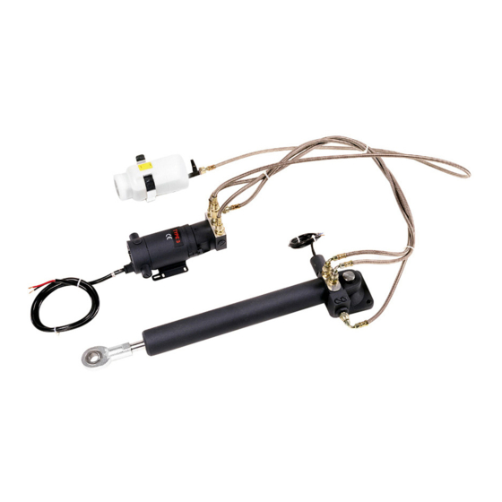
Hydraulic linear drive

Advertisement

Hydraulic Linear Drive
Installation instructions
E12207 Type 2 (12 V )
E12208 Type 2 (24 V )
M81202 Type 3 (12 V )
M81203 Type 3 (24 V )

Advertisement

Table of Contents
loading

Summary of Contents for Raymarine E12207

  • Page 1 Hydraulic Linear Drive Installation instructions E12207 Type 2 (12 V ) E12208 Type 2 (24 V ) M81202 Type 3 (12 V ) M81203 Type 3 (24 V )
  • Page 3 , RayTech Navigator, RayTalk, Sail Pilot, SeaTalk, SeaTalk , SeaTalk and Sportpilot are registered trademarks of Raymarine UK Limited. Seahawk, Smartpilot, Pathfinder and Raymarine are registered trademarks of Raymarine Holdings Limited. All other product names are trademarks or registered trademarks of their respective owners. Fair Use Statement You may print no more than three copies of this manual for your own use.
  • Page 5: Table Of Contents

    5.2 Bleeding the system ..........36 2.7 Parts required ............16 5.3 Troubleshooting ............37 2.8 Location and mounting requirements ......16 5.4 Raymarine technical support........38 2.9 Product differences ........... 18 Appendix A Technical specification ....... 39 2.10 Dimensions............. 18...
  • Page 6 Hydraulic Linear Drive Installation instructions...
  • Page 7: Chapter 1 Important Information

    Raymarine recommends certified installation by a Raymarine approved installer. A certified installation qualifies for enhanced Handbook information product warranty benefits. Contact your Raymarine dealer for further details, and refer to the separate warranty document packed This handbook contains important information regarding the with your product.
  • Page 8: Emc Conformance

    It is the user’s responsibility to use official government charts, notices to mariners, caution and proper navigational skill when operating this or any other Raymarine EMC conformance product. Raymarine equipment and accessories conform to the appropriate Electromagnetic Compatibility (EMC) regulations for use in the recreational marine environment.
  • Page 9: Technical Accuracy

    Whilst the WEEE Directive does not apply to some possible separation between different items of electrical Raymarine products, we support its policy and ask you to be aware equipment, to provide the best conditions for EMC performance of how to dispose of this product.
  • Page 10: Warranty Registration

    To register your Hydraulic Linear Drive ownership, please take a few minutes to fill out the warranty registration card found in the box, or visit www.raymarine.com and register on-line. It is important that you register your product to receive full warranty benefits.
  • Page 11: Chapter 2 Planning

    Chapter 2: Planning Chapter contents • 2.1 Installation checklist on page 12 • 2.2 Drive types on page 12 • 2.3 Reservoir on page 13 • 2.4 Product overview on page 13 • 2.5 Typical system on page 14 • 2.6 Parts supplied on page 15 •...
  • Page 12: Installation Checklist

    2.1 Installation checklist 2.2 Drive types Installation includes the following activities: There are 2 drive types. Each drive type has 2 variants (one for 12 V systems, one for 24 V systems). Installation Task Although the core functionality of each drive type is essentially the Plan your installation.
  • Page 13: Reservoir

    2.4 Product overview The Hydraulic Linear Drive is intended to operate a vessel’s steering mechanism as part of a Raymarine autopilot system. The Hydraulic Linear Drive is designed for vessels with existing mechanical steering systems, NOT hydraulic steering systems. It is mounted below decks and moves the rudder directly by pushing the tiller arm or rudder quadrant.
  • Page 14: Typical System

    2.5 Typical system 7. Push rod — extends out of the hydraulic ram casing to control the tiller arm or rudder quadrant. The drive components connect to a course computer as part of an 8. Hydraulic ram — a self-contained autopilot steering cylinder autopilot system.
  • Page 15: Parts Supplied

    2.6 Parts supplied • Bolts (quantity: 4) • Washers (quantity: 4). • Lock nuts (quantity: 4). 4. Pump mounting screw pack, consisting of: • Bolts (quantity: 2) • Washers (quantity: 2). • Lock nuts (quantity: 2). 5. Installation instructions. 6. Hydraulic fluid transit container. 1.
  • Page 16: Parts Required

    2.7 Parts required 2.8 Location and mounting requirements Hydraulic ram Additional parts required, NOT supplied with the product. Location and mounting requirements: The following additional parts are required for the installation of the Hydraulic Linear Drive: • MUST be mounted on a very solid structure (for example, a substantial frame member of your vessel).
  • Page 17 • MUST be accessible for hydraulic fluid top-ups and refills. • Raymarine recommends the use of M8 bolts and suitable nuts and washers to secure the reservoir to the vessel. Pipes The pipes transport fluid and pressure around the Hydraulic Linear Drive system.
  • Page 18: Product Differences

    • For the existing Type 2 drive (M81200, M81201) the pipes that transported the hydraulic fluid to the ram unit were connected to the top of the unit. For the NEW Type 2 drive (E12207, E12208), the pipes connect to the rear of the unit. You must allow at least 17 cm (6.7 in) clearance at the rear of the unit for the extruding...
  • Page 19: Dimensions

    2.11 Dimensions Type 3 drive Reservoir dimensions. 690 mm (27.15 in) 457 mm (18 in) 148.7 mm (5.85 in) 9.5 mm (0.37 in) D11856-1 1. Hydraulic ram at mid stroke position. D11901-1 Planning...
  • Page 20 Hydraulic Linear Drive Installation instructions...
  • Page 21: Chapter 3 Mounting

    Chapter 3: Mounting Chapter contents • 3.1 Mounting checklist on page 22 • 3.2 Hydraulic ram alignment on page 22 • 3.3 Hydraulic ram mounting on page 24 • 3.4 Steering system connection on page 24 • 3.5 Hydraulic pump mounting on page 26 •...
  • Page 22: Mounting Checklist

    3.1 Mounting checklist 3.2 Hydraulic ram alignment Mounting the Hydraulic Linear Drive system involves the following When mounting the hydraulic ram ensure it is correctly aligned. tasks: Hydraulic ram Mounting Task • The hydraulic ram must be at right angles to the mounting surface. Ensure you have read and understood the 2.8 Location and mounting •...
  • Page 23 Push rod and tiller arm Note: Accurate angular alignment of the hydraulic ram is extremely important. You must NOT exceed the specified degree The push rod must be accurately aligned with the tiller arm plane alignment limits under any circumstances. of rotation.
  • Page 24: Hydraulic Ram Mounting

    3.3 Hydraulic ram mounting 3.4 Steering system connection The rod end of the hydraulic ram must be connected to the vessel’s Mount the hydraulic ram as securely as possible to ensure it tiller arm or rudder quadrant. performs reliably and remains correctly aligned. Before connecting the hydraulic ram to the steering system, ensure •...
  • Page 25 7. Lock nut. flange remains above the arm. 8. Tiller pin. ii. Ensure the tiller pin is a tight fit in the tiller arm. Raymarine recommends the use of a suitable adhesive around the tiller 9. Hole diameter, as follows: pin.
  • Page 26: Hydraulic Pump Mounting

    3.5 Hydraulic pump mounting The hydraulic pump must be mounted in a suitable location to ensure reliable performance. • Before mounting the hydraulic pump, refer to the guidance provided in the 2.8 Location and mounting requirements section. • Drill 2 mounting holes. •...
  • Page 27: Reservoir Mounting

    3.6 Reservoir mounting 3.7 Filling the reservoir The reservoir must be mounted on a bulkhead as far above the The hydraulic fluid reservoir is supplied empty and must be filled to pump and hydraulic ram as possible. the correct level with the supplied hydraulic fluid. Do NOT attempt to move or operate the hydraulic push rod before •...
  • Page 28 Hydraulic Linear Drive Installation instructions...
  • Page 29: Chapter 4 Cables And Connections

    Chapter 4: Cables and connections Chapter contents • 4.1 General cabling guidance on page 30 • 4.2 Clutch connection on page 31 • 4.3 Course computer connection on page 32 • 4.4 Post-installation check on page 34 Cables and connections...
  • Page 30: General Cabling Guidance

    • Unless otherwise stated use only standard cables of the correct type, supplied by Raymarine. Strain relief • Ensure that any non-Raymarine cables are of the correct quality Ensure adequate strain relief is provided. Protect connectors from and gauge. For example, longer power cable runs may require strain and ensure they will not pull out under extreme sea conditions.
  • Page 31: Clutch Connection

    4.2 Clutch connection The clutch (bypass valve) on the hydraulic ram unit must be connected to the clutch terminals on the course computer, and a suitable ground. The clutch is used to bypass the hydraulic ram and operate the steering system manually when there is a problem with the autopilot system.
  • Page 32: Course Computer Connection

    4.3 Course computer connection Hydraulic Linear Course The Hydraulic Linear Drive must be connected to an SPX-30 course Item Drive computer Description computer. Clutch Adjust the voltage setting to match the voltage voltage rating specified on the Hydraulic selector ram clutch. switch Hydraulic Clutch (+)
  • Page 33 Use suitable electrical connectors or junction boxes to connect the Note: For complete connection and installation instructions for Hydraulic Linear Drive cables to the cable extensions. the course computer refer to the documentation that accompanies the unit. Note: Do NOT untwist the pump cables or remove the suppression ferrite.
  • Page 34: Post-Installation Check

    4.4 Post-installation check Check Ensure that you’ve completed the hand-steering check (see Steering Check the following points after installing the drive and connecting check). the course computer: Ensure the course computer’s clutch switch is in the correct position Check (refer to 4.3 Course computer connection).
  • Page 35: Chapter 5: Maintenance And Troubleshooting

    Chapter 5: Maintenance and troubleshooting Chapter contents • 5.1 Maintenance checks on page 36 • 5.2 Bleeding the system on page 36 • 5.3 Troubleshooting on page 37 • 5.4 Raymarine technical support on page 38 Maintenance and troubleshooting...
  • Page 36: Maintenance Checks

    5.1 Maintenance checks 5.2 Bleeding the system Regular maintenance is required to ensure optimum operation. Note: Raymarine recommends that bleeding the system is undertaken by an authorized Raymarine dealer. Regular checks Before commencing ensure the oil and any storage containers are •...
  • Page 37: Troubleshooting

    5.3 Troubleshooting Potential problems with the Hydraulic Linear Drive system and possible causes and solutions are described here. Problem Possible causes Possible solutions Motor does not run. The motor has no power supply. Check all electrical connections. The motor is not receiving instructions Check the connection between the autopilot control head and the course from the course computer.
  • Page 38: Raymarine Technical Support

    Web support Please visit the customer support area of our website at: www.raymarine.com This contains Frequently Asked Questions, servicing information, e-mail access to the Raymarine Technical Support Department and details of worldwide Raymarine agents. Telephone support In the USA call:...
  • Page 39: Appendix A Technical Specification

    Appendix A Technical specification Specification (at nominal voltage) Type 2 Type 3 Maximum vessel 22000 kg (48500 lb) 35000 kg (77000 lb) displacement Peak thrust 675 kg (1488 lb) 1000 kg (2200 lb) Maximum stroke 254 mm (10 in) 300 mm (12 in) Hardover to hardover 10 seconds 12 seconds...
  • Page 40 Hydraulic Linear Drive Installation instructions...
  • Page 42 www.raymarine.com...

This manual is also suitable for:

E12208M81202M81203

Table of Contents