Air Monitor VOLU-flo/OAM II Installation, Operation And Maintenance Manual
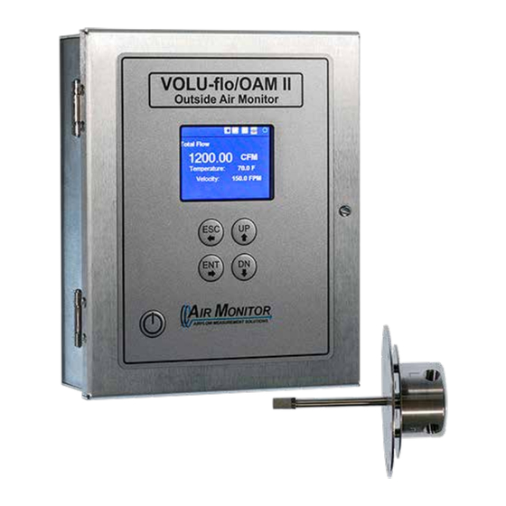
Transmitter
differential pressure airflow & temperature measurement system
Hide thumbs
Also See for VOLU-flo/OAM II:
- Application manual (9 pages) ,
- Installation and operation manual (44 pages)

Subscribe to Our Youtube Channel
Related Manuals for Air Monitor VOLU-flo/OAM II


Summary of Contents for Air Monitor VOLU-flo/OAM II
- Page 1 VOLU-flo/OAM II Transmitter Version 1.2 Differential Pressure Airflow & Temperature Measurement System Installation, Operation and Maintenance Manual www.airmonitor.com • 1-800-AIRFLOW...
- Page 2 • All rights reserved. No part of this manual may be reproduced in any form without Air Monitor’s written permission. • Air Monitor makes no warranty of any kind with regard to this material, including, but not limited to, implied warranties of merchantability and suitability for a particular purpose.
-
Page 3: Table Of Contents
TABLE OF CONTENTS GENERAL INFORMATION ...................4 PURPOSE OF THIS GUIDE ................4 TYPICAL METER INSTALLATION ............4 SPECIFICATIONS ..................6 CHECKING THAT YOU RECEIVED EVERYTHING .........7 WORKING ENVIRONMENT ..............7 SERIAL NUMBER ..................7 INSTALLATION .....................8 SITE SELECTION ..................8 ENCLOSURE INSTALLATION ..............9 AIRFLOW SENSORS ..................10 AIRFLOW SENSOR INSTALLATION ............11 AIRFLOW SENSOR INSTALLATION DETAIL .........12 AIRFLOW SENSOR PROCESS CONNECTIONS ........14... -
Page 4: General Information
Thank you for purchasing the OAM II Outdoor Airflow Measurement System. As our valued customer, Air Monitor’s commitment to you is to provide quality service and support while continuing to offer you accurate, reliable products to meet your flow measurement needs. - Page 5 The example above illustrates a dual OA inlet (two inlets providing outside air to separate air handlers). In this application, the VOLU-flo/OAM II would be configured for dual mode operation. Separate flow readings will be reported for each channel in this mode.
-
Page 6: Specifications
SPECIFICATIONS SENSING METHOD Channel 2 transducer: 316 stainless steel ¼” NPT Differential pressure is measured across a fixed inlet compression fittings for channel 2 Dual mode or as the resistance along with temperature. Sensor readings are maximum pressure port Split Min/Max mode used to calculate and report velocity, volumetric flow and Temperature: 3-wire RTD terminal block connections temperature data. -
Page 7: 1.4 Checking That You Received Everything
1.4 CHECKING THAT YOU RECEIVED EVERYTHING Carefully open the VOLU-flo/OAM II shipping container(s) and remove all equipment. Inspect equipment for any damage. If damaged, contact Air Monitor and your freight company. Verify that the following items have been shipped: • 1 OAM transmitter •... -
Page 8: Installation
The OAM II Airflow Measurement System should be installed by experienced HVAC technicians and others with related knowledge and experience with air flow systems. Air Monitor support personnel are available to assist with technical recommendations and to provide guidance by telephone and/or e-mail. -
Page 9: Enclosure Installation
(4) Machine screws - HHMS .25-20 x 1.5” • (4) Wood screws - FHLS .25 x 1.5” • (4) Concrete screws - HHCS .25 x 1.5” 8.16 8.20 7.00 6.00 OPT. VOLU-flo/OAM II Outside Air Monitor WINDOW 9.10 10.25 10.77 10.30 VOLU-flo/OAM II Outside Air Monitor 2.75 4X Ø.312... -
Page 10: Airflow Sensors
AIRFLOW SENSORS Air Monitor provides airflow sensors in pre-fabricated airflow stations and as separate Uni-sensors as shown below. OAM II Airflow Station (shown with a single Uni-sensor) VOLU-flo/OAM ll OU TSID E AIR MONITOR OAM II Airflow Station OAM Airflow Station OAM II stations are built to order and provided fully assembled. -
Page 11: Airflow Sensor Installation
63% open area, 0.05” thickness, 0.50” SWD x 1.25” LWD x 0.096” strand width. Air Monitor recommends that signal tubing between the transmitter enclosure and all sensors be 1/4” OD stainless steel or copper. Use tees or manifolds when combining multiple sensor signals at the transmitter input. -
Page 12: Airflow Sensor Installation Detail
Inlets with an Aspect Ratio > 6:1 • Inlets with an aspect ratio > 6:1 require the use of multiple uni-sensors spaced at equidistant intervals. For example: A 2’ x 30’ louvered inlet has aspect ratio of 15:1. Use three equally spaced sensors serving 2’ x 10’ areas, to reduce the aspect ratio to 5:1 for each sensor. - Page 13 FLOW FLOW Uni-sensors Uni-sensors are installed in ductwork or attached to an inlet using the hardware provided. Air Monitor recommends that signal tubing between the transmitter enclosure and all sensors be 1/4” OD stainless steel or copper. UV resistant flexible plastic tubing specifically designed for outdoor use, such as Tygon R-3400 or equivalent, may also be used.
-
Page 14: Airflow Sensor Process Connections
• Tighten nut one-half turn past finger tight. AIRFLOW SENSOR PROCESS CONNECTIONS Air Monitor recommends that signal tubing between the transmitter enclosure and all sensors be 1/4” OD stainless steel or copper. Use tees or manifolds when combining multiple sensor signals at the transmitter input. -
Page 15: Power/Signal Connections
POWER/SIGNAL CONNECTIONS Power and signal connections are made at the terminal blocks shown below. Input power wiring should be 14 to 18 AWG. Signal wiring should be 18 to 22 AWG. The maximum wire gauge that the terminal strips can accommodate is 14AWG. No more than two wires should be connected to any one terminal. -
Page 16: Operation
OPERATING MODES The displayed information is dependent on the configuration of the OAM II (operating mode). The operating modes for the VOLU-flo/OAM II is are Low Flow (Std.), Extended (Ext), Split Min/ Max and Dual. Low Flow – Single transducer (100-600 FPM) Extended –... -
Page 17: Status Bar
The Main System Display for Split/Ext/Low The Main System Display for Dual STATUS BAR An upper status bar is always displayed indicating the general operational status of the unit. The following status’ are indicated on the upper left hand corner of the display: Message Blue on Blue Normal Operation... -
Page 18: Main Menu
Password Menu If the password has been set previously, the following screen will be displayed: Enter the password and you will be brought to the menus selection screen. Infomation regarding the password settings can be found in the Service Menu and is discussed later in this manual. -
Page 19: Flow Configuration (Low/Ext)
Units System - Select between SI or US. The dropdowns for flow and velocity will present the units for the system selected. Conditions - Select between actual and standard flow conditions. This affects the flow results, so make sure you select the correct conditions for your application. Standard flow normalizes data to 68 °F and 29.92”... - Page 20 Design Flow Max This is the upper flow limit based on the selected transducers. The value entered cannot exceed corresponding DP span of the installed transducer. The transducers DP span controls the maximum flow which can be achieved. The user should set this value to a range which they expect represents the duct or inlet they are monitoring.
-
Page 21: Display Configuratin (Low/Ext/Split/Dual)
DISPLAY CONFIGURATION (LOW/EXT/SPLIT/DUAL) This screen has the same dialog items for all modes, but choices in the dialog items varies depending on Equipment Type. Line 1 Parameter - This is mandated as flow. It has no other options Line 2 Parameter - Low/Ext –... -
Page 22: Filter And Lockdown Settings
FILTER AND LOCKDOWN SETTINGS For each mode, there is a slight difference in the dialog settings: Dual Low/Ext Split Process Filter - The process filter is used to smooth the signal fed to the analog outputs. The settings are from 1-10, where 1 is the softest filter and 10 is the hardest filter. Typically, 2-4 will give a filtered signal which is responsive, but provides some dampening. -
Page 23: Transducer Configuration
This menu page varies based on operating mode. Ext/Split/Dual Transducer/Transducer 1/Transducer 2 - Transducer selections must match the installed transducers. Contact Air Monitor for assistance if you believe you need to install different transducers. CAUTION Do NOT change this setting without changing the installed transducer. Doing so will cause significant flow measurement errors. -
Page 24: Field Characterization
FIELD CHARACTERIZATION This menu allows the user to field characterize (FC) system flow and adjust the factory calibration parameters in the OAM II. When FC is enabled, the icon shown below appears in the status bar of the main display. When operating in Split Min/Max or Dual mode, there are two icons shown indicating that both inlets have been characterized. -
Page 25: Service Menu
SERVICE MENU The Service Menu is designed to allow a user to set parameters for the system, perform field calibrations and view system information. When the user selects the Service Menu option the following menu will be seen: PASSWORD To change the password, enter your new password into the editable field. -
Page 26: Analog Output Calibration
ANALOG OUTPUT CALIBRATION The following proceedure allows for field calibration, when required. This menu will guide the user through the steps of the calibration. The icons on the screen indicate the “Output Type” setting that entered in the Analog Output Configuration screen. Current Icon Voltage Icon To use this screen, select the output you wish to calibrate. -
Page 27: Factory Settings
FACTORY SETTINGS This menu allows the user to return the system back to the factory settings. IMPORTANT NOTE Returning OAM II to factory settings will erase all field characterization data. PRODUCT INFORMATION This screen provides system set up data. AUTOZERO AND ANALOG OUTPUT TEST This menu is used to validate that the outputs are in calibration and the Autozero function is working. -
Page 28: Communications
CAUTION Do not connect shield drains to the common terminal. Air Monitor recommends that 3-wire systems with a separate shield be used for communications. The interface can operate on 2-wire networks with no common, but this configuration is more susceptible to noise. - Page 29 Alpha-numeric; 20 char limits. See “Custom ID” setting in the Service Menu. Object Type Device Read-only System Status Operational Read-only Vendor Name Air Monitor Corporation Read-only Vendor ID Read-only Model Name OAM-II Read-only Location Default Location Read-only Description Airflow Measurement...
- Page 30 Analog Inputs Object Identifer Analog Input-0 to Analog Input-X1 Read-only Object Name Various Read-only Object Type Analog-Input Read-only Present Value REAL Read-only Status Flags F, F, F, F Read-only Event State Normal Read-only Out of Service FALSE Read-only Description Various Read-only Units Various...
- Page 31 DESCRIPTION REGISTER TYPE DATA TYPE DESCRIPTION ADDRESS System Velocity Units Read Input 40201 uint16_t 1 = FPM, 2 = FPS, 3 = MPM, 4 = MPS System Flow Units Read Input 40202 uint16_t 1 = CFM, 2 = CFH, 3 = L/S, 4 = L/M, 5 = M3H System Version Read Input...
-
Page 32: Maintenance
• Inspect wiring to the OAM II for good connections and absence of corrosion. Calibration Intervals Air Monitor does not recommend a specific time interval between re-calibrations. Calibrations should be scheduled to meet the needs of the facility where the OAM II is installed. -
Page 33: Warranty Information
The warranty set forth above is in lieu of all other warranties either express or implied and constitutes the full extent of Air Monitor Corporation’s liability to the customer, or any other party, for breach of warranty.
Need help?
Do you have a question about the VOLU-flo/OAM II and is the answer not in the manual?
Questions and answers