
Subscribe to Our Youtube Channel
Related Manuals for Air Monitor ELECTRA-FLO G5


Summary of Contents for Air Monitor ELECTRA-FLO G5
- Page 1 ELECTRA-flo G5 ELECTRA-flo G5 Thermal Airflow Transmitter Thermal Airflow Transmitter Installation and Operation Manual Installation and Operation Manual DOC-0002681 Rev.D...
- Page 2 • All rights reserved. No part of this manual may be reproduced in any form without Air Monitor’s written permission. • Air Monitor makes no warranty of any kind with regard to this material, including, but not limited to, implied warranties of merchantability and suitability for a particular purpose.
-
Page 3: Table Of Contents
ELECTRA-flo G5 TRANSMITTER TABLE OF CONTENTS SECTION 1.0 GENERAL INFORMATION .................. 4 1.1 PURPOSE OF THIS GUIDE ........................4 1.2 TYPICAL THERMAL AIRFLOW MEASUREMENT SYSTEM INSTALLATION ......4 1.3 STANDARD FEATURES AND SPECIFICATIONS* ................5 1.4 MODEL NUMBER CODIFICATION .......................6 1.5 CHECKING THAT YOU RECEIVED EVERYTHING ................7 1.6 WORKING ENVIRONMENT ........................7... -
Page 4: Section 1.0 General Information
SECTION 1.0 Thank you for purchasing the ELECTRA-flo 5 Series Thermal Airflow Measurement GENERAL System. As our valued customer, Air Monitor’s commitment to you is to provide fast, reliable service and assistance while continuing to offer you the most INFORMATION accurate and reliable products to meet your flow measurement needs. -
Page 5: Standard Features And Specifications
ELECTRA-flo G5 TRANSMITTER 1.3 STANDARD FEATURES AND SPECIFICATIONS* ELECTRA-flo G5 Transmitter PERFORMANCE SYSTEM Single or dual channel operation CONFIGURATION Supports up to 32 individual thermal dispersion airflow sensors Provides airflow velocity, flow and temperature Supports multiple airflow measurement system types... -
Page 6: Model Number Codification
ELECTRA-flo G5 TRANSMITTER 1.4 MODEL NUMBER CODIFICATION Model Number Coding = E-flo G5-AB-CDEF (-SPC) Electra-flo G5 Transmitter A= Feature Set D = Communications 1 = Thermal dispersion airflow transmitter with backlit 0 = None graphical LCD, two (2) programmable analog outputs 1 = RS485, BACnet MS/TP or MODBUS RTU and RS485 serial communication. -
Page 7: Checking That You Received Everything
-20°F to 140°F. 1.7 SERIAL NUMBER The serial number of your ELECTRA-flo G5 transmitter is located outside of the enclosure. The serial number is a unique identifier for your product. Please have it available when contacting Air Monitor for assistance regarding your product. -
Page 8: Section 2.0 Installation
Careful attention to the site selection for the system components will help the installers with the initial installation, reduce start-up problems, and make future maintenance easier. For example, do not install the ELECTRA-flo G5 transmitter where it will be difficult for personnel to perform periodic maintenance. When selecting a site for mounting the system components, consider the criteria under Section 1.6: WORKING ENVIRONMENT, as well as the following:... -
Page 9: Transmitter Dimensions
ELECTRA-flo G5 TRANSMITTER 2.2 TRANSMITTER DIMENSIONS NEMA 4X- FIBERGLASS NEMA 4X- STAINLESS STEEL NEMA 1 ENCLOSURE ENCLOSURE ENCLOSURE 8.3" 8.5" 4.9" 6.0" 6.0" 3.5" ELECTRA-flo G5 Thermal Airflow Transmitter ELECTRA-flo G5 Thermal Airflow Transmitter 7.8" 7.4" 6.9" 10.5" 10.9" 10.3"... -
Page 10: Transmitter Installation
(4) Wood screws - FHLS .25 x 1.5” (4) Concrete screws - HHCS .25 x 1.5” The ELECTRA-flo G5 transmitter can be mounted in any position provided it is secured using all four mounting holes. Reasonable consideration should be given to clearances for electrical connections. -
Page 11: Electra-Flo G5 Power/ Signal Connections
• 24 VDC (20-28 VDC), 16-50 W, varies based on number of sensors. 2. Alarm can be set for either flow or temperature with upper and lower limits. Refer to page 18 for more information. 2.4.2 ELECTRA-flo G5 Analog Outputs & Serial Communication ANALOG OUTPUT AND SERIAL COMMUNICATIONS TERM... -
Page 12: Section 3.0 Operation
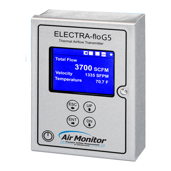
74.23 FRONT VIEW Custom ID Default Dual Channel Display Screens The true dual channel version of the ELECTRA-flo G5 transmitter has two display screens for process data. Sys1 Flow and Sys2 Flow are provided on the first Sys1 Flow 75.6F screen. -
Page 13: User Interface/ Device Configuration
Send/Receive arrows flashing indicates the sensor(s) and transmitter are Communicating normally 3.2 USER INTERFACE/ DEVICE The ELECTRA-flo G5 transmitter is fully field configurable. The transmitter is CONFIGURATION configured using the display and 4-button membrane keypad. Individual key functions are described below. - Page 14 ELECTRA-flo G5 TRANSMITTER Configuration Menus MAIN MENU SELECTION DESCRIPTION Density Compensation Select density compensation type for flow output (Actual or Standard CFM) Select System of Units Select system of units (US or SI) Select Units of Measure Select velocity and flow units...
-
Page 15: Main Menu
Density Compensation - Density compensation can be selected to be actual Density Compensation flow or flow corrected to standard conditions. The default factory setting is for actual conditions. The ELECTRA-flo G5 also allows for inputting the site elevation, Conditions: Standard... - Page 16 Inactivity Timeout - The time period which holds the display in menu mode. When the timer expires, the display is returned to the main display screen showing the process values. IMPORTANT NOTE The optional true dual channel version of the ELECTRA-FLO G5 only displays flow. Air Monitor Corporation 800.AIR.FLOW Page 16...
- Page 17 ELECTRA-flo G5 TRANSMITTER 3.3 MAIN MENU (CONTINUED) Analog Output Configuration Analog Output Configuration The ELECTRA-flo G5 transmitter is equipped with dual analog outputs. The Analog Output Configuration menu configures the analog output type, Output Type: 4-20 mA parameter and filter.
- Page 18 ELECTRA-flo G5 TRANSMITTER 3.3 MAIN MENU (CONTINUED) Display Averaging Filter Display Averaging Filter The Display Averaging Filter filters the data shown on the display. It affects all elements of the display. The filter has 1-10 settings; 1 is the lightest filter, and 10 Filter: represents the heaviest filter.
-
Page 19: Network Configuration
ELECTRA-flo G5 TRANSMITTER 3.4 NETWORK CONFIGURATION Network Configuration Network Configuration The ELECTRA-flo G5 is provided with BACnet MS/TP and Modbus RTU as serial communications protocol options. BACnet is the default setting. The field Type: BACnet configurable serial communications interface is described on the following... - Page 20 ELECTRA-flo G5 TRANSMITTER 3.4 NETWORK CONFIGURATION PROTOCOL IMPLEMENTATION STATEMENT (CONTINUED) BACnet Protocol Revision: 12 Device Profile (Annex L): BACnet Application Specific Controller (B-ASC) MS/TP master (Clause 9), baud rate(s): 9600, 19200, 38400, 56700, 76800, 115200 Device Address Binding: No BBMD Support Registration By Foreign Devices: No Character Set Supported: ANSI X3.4...
- Page 21 ELECTRA-flo G5 TRANSMITTER STANDARD OBJECT TYPES SUPPORTED Device Object Property Default Value Read-Only Comment or Writable Object Identifier Writable 0 – 4,194,303 Object Name ELECTRA-flo Writable Alpha-numeric; 16 char limit. Linked to “Custom ID” setting in the Service Menu. Also displays on the bottom of the LCD display on transmitter.
- Page 22 ELECTRA-flo G5 TRANSMITTER The Air Monitor BACnet stack supports the optional property “DESCRIPTION”. This is used to indicate the type of information in the object. For example, for an ELECTRA-flo system, the description will indicate as “Total Flow” for average flow, or “Avg Temp”...
- Page 23 17, Report Slave ID. When a message is sent to the meter requesting the slave ID, the following message is returned: ELECTRA-flo G5 The meter will report data in decimal or HEX, depending on the control system settings. The data must be converted from decimal/HEX to ASCII in order to form the string.
- Page 24 ELECTRA-flo G5 TRANSMITTER ELECTRA - FLO G5 MODBUS REGISTERS MODBUS INPUT REGISTERS DEVICE FLOW TEMPERATURE UNITS Address Data Type Address Data Type System Average 30000 float 30002 float see Register 30201 DEVICE VELOCITY TEMPERATURE UNITS Sensor 1 30004 float 30006...
- Page 25 1 = ON, 0 = OFF System Reset 00002 boolean 1 = RESET K-factor 00003 boolean Returns the state of the K-factor DESCRIPTION Function Code DATA TYPE DESCRIPTION report slave ID 17000 ASCII Returns string "ELECTRA-flo G5" Air Monitor Corporation 800.AIR.FLOW Page 25 airmonitor.com...
- Page 26 ELECTRA-flo G5 TRANSMITTER ELECTRA - FLO G5 DUAL MODBUS REGISTERS MODBUS INPUT REGISTERS DEVICE FLOW TEMPERATURE UNITS Address Data Type Address Data Type System 1 Average 30000 float 30002 float see Register 30401 DEVICE VELOCITY TEMPERATURE UNITS Sensor 1 30004...
- Page 27 ELECTRA-flo G5 TRANSMITTER Sensor 2 30208 float 30210 float see Register 30400 Sensor 3 30212 float 30214 float see Register 30400 Sensor 4 30216 float 30218 float see Register 30400 Sensor 5 30220 float 30222 float see Register 30400 Sensor 6...
- Page 28 K-factor 1 00004 boolean Returns the state of the K-factor K-factor 2 00005 boolean Returns the state of the K-factor DESCRIPTION ADDRESS DATA TYPE DESCRIPTION report slave ID ASCII Returns string "ELECTRA-flo G5" Air Monitor Corporation 800.AIR.FLOW Page 28 airmonitor.com...
-
Page 29: Field Characterization
ELECTRA-flo G5 TRANSMITTER 3.5 FIELD CHARACTERIZATION Field Characterization Field Characterization Field Characterization (K-factoring) of a flow element is the adjustment of the flow measurement system to match a known reference measurement (for our reference - most commonly airflow traverse testing). Field Characterization is... -
Page 30: Service Menu
Disabled ESC - Leave Sensor Enable/Disable Sensor Control An enabled sensor will report measurement data to the ELECTRA-flo G5 transmitter. This is the default condition after initially powering the system. Sensor 1: Disabled A disabled sensor will not report measurement data to the ELECTRA-flo... - Page 31 ENT - Accept ESC - Del/Leave UP/DN - Change Product Information Product Information This menu page provides information about the ELECTRA-flo G5 transmitter hardware and firmware. It also includes information on the number of probes and WO #: 90525 nodes connected to the transmitter.
-
Page 32: Section 4.0 Maintenance, Inspections, Troubleshooting
3. The probe-to-probe and probe-to-transmitter cables and connections are properly connected and secure. 4. Power cycle the transmitter. If, after following the above troubleshooting steps, the ELECTRA-flo G5 transmitter continues to operate improperly, contact Air Monitor for technical assistance. Air Monitor Corporation 800.AIR.FLOW Page 32 airmonitor.com... - Page 33 ELECTRA-flo G5 TRANSMITTER 1050 Hopper Ave • Santa Rosa, CA 95403 • USA • (P) 707.544.2706 • airmonitor.com...
Need help?
Do you have a question about the ELECTRA-FLO G5 and is the answer not in the manual?
Questions and answers