
Related Manuals for Air Monitor ELECTRA-flo G5


Summary of Contents for Air Monitor ELECTRA-flo G5
- Page 1 ELECTRA-flo G5 Transmitter Version 1.0X Thermal Airflow & Temperature Measurement System Installation, Operation and Maintenance Manual www.airmonitor.com • (800) AIRFLOW...
- Page 2 • All rights reserved. No part of this manual may be reproduced in any form without Air Monitor’s written permission. • Air Monitor makes no warranty of any kind with regard to this material, including, but not limited to, implied warranties of merchantability and suitability for a particular purpose.
-
Page 3: Table Of Contents
ANALOG OUTPUT SIGNALS ..............25 MAINTENANCE / INSPECTIONS .................25 MAINTENANCE / INSPECTIONS ..............25 TROUBLESHOOTING ................25 WARRANTY ......................26 1050 Hopper Ave, Santa Rosa, CA 95403 • Tel (800) AIRFLOW • www.airmonitor.com amcsales@airmonitor.com ELECTRA-flo G5 Transmitter Thermal Airflow & Temperature Measurement System 1015-3 - 07/18... -
Page 4: General Information
This is NOT, nor is it intended to be an electrical or HVAC trade manual. This manual is the basic reference tool for the ELECTRA-flo G5 Transmitter, including its power connection and associated outputs. The complete system consists of the transmitter and associated probe arrays or stations. -
Page 5: Specifications
PROBE SIZE RANGE 6” to 144” dimension length 1050 Hopper Ave, Santa Rosa, CA 95403 • Tel (800) AIRFLOW • www.airmonitor.com amcsales@airmonitor.com ELECTRA-flo G5 Transmitter Thermal Airflow & Temperature Measurement System 1015-3 - 07/18... -
Page 6: Installation
Service Department at 1-800-AIRFLOW for assistance. 3.2 INSTALLATION LOCATION GUIDELINES • The standard version of the ELECTRA-flo G5 transmitter and probe connection heads have a NEMA 1 enclosure rating suitable for clean and dry indoor locations. For additional protection, an enclosure with an adequate NEMA rating may be required. Please contact your Air Monitor representative for enclosure options. -
Page 7: Power And Signal Connections
• Tools Required: Electric drill; #25 (0.1495”) drill bit; screwdriver or nut driver (as required for customer supplied mounting screws); and four #8-32 self-tapping machine screws. • The ELECTRA-flo G5 transmitter can be mounted in any position provided it is secured using all four mounting holes. - Page 8 Power Connections: Terminal J4, pin 1 for Line (L +), pin 2 for Neutral (N -) and pin 3 for Ground (G). See figure below for details. The ELECTRA-flo G5 can be powered by either 20-28VAC 50/60 Hz or 20-40VDC.
-
Page 9: Configuration
Configure alarm type, upper and lower limits Field Characterization For information on field characterization, please see page 19 below 1050 Hopper Ave, Santa Rosa, CA 95403 • Tel (800) AIRFLOW • www.airmonitor.com amcsales@airmonitor.com ELECTRA-flo G5 Transmitter Thermal Airflow & Temperature Measurement System 1015-3 - 07/18... - Page 10 Configure Number of probes and sensors per probe NETWORK CONFIGURATION DESCRIPTION Network Configuration Configure BACnet MS/TP or MODBUS RTU Network Connection 1050 Hopper Ave, Santa Rosa, CA 95403 • Tel (800) AIRFLOW • www.airmonitor.com amcsales@airmonitor.com ELECTRA-flo G5 Transmitter Thermal Airflow & Temperature Measurement System 1015-3 - 07/18...
- Page 11 Density Compensation - Density compensation can be selected to be actual flow or corrected to standard conditions. Default factory setting is for actual conditions. The ELECTRA-flo G5 also allows for inputting the site elevation, which will add density compensation for average atmospheric pressure based upon elevation above sea level.
- Page 12 It also has an ‘Off’ setting. ENT - Accept ESC - Del/Leave UP/DN - Change 1050 Hopper Ave, Santa Rosa, CA 95403 • Tel (800) AIRFLOW • www.airmonitor.com amcsales@airmonitor.com ELECTRA-flo G5 Transmitter Thermal Airflow & Temperature Measurement System 1015-3 - 07/18...
- Page 13 “SH”. WARNING Do not connect shield drains to the “G” terminal. 1050 Hopper Ave, Santa Rosa, CA 95403 • Tel (800) AIRFLOW • www.airmonitor.com amcsales@airmonitor.com ELECTRA-flo G5 Transmitter Thermal Airflow & Temperature Measurement System 1015-3 - 07/18...
- Page 14 Device Management – Dynamic Object Binding-B (DM-DOB-B) Device Management – Device Communication Control-B (DM-DCC-B) Device Management – Reinitialize Device-B (DM-RD-B) 1050 Hopper Ave, Santa Rosa, CA 95403 • Tel (800) AIRFLOW • www.airmonitor.com amcsales@airmonitor.com ELECTRA-flo G5 Transmitter Thermal Airflow & Temperature Measurement System 1015-3 - 07/18...
- Page 15 Out of Service FALSE Read-only Description Various Writable Location Various Writable Units Various Read-only 1050 Hopper Ave, Santa Rosa, CA 95403 • Tel (800) AIRFLOW • www.airmonitor.com amcsales@airmonitor.com ELECTRA-flo G5 Transmitter Thermal Airflow & Temperature Measurement System 1015-3 - 07/18...
- Page 16 The Air Monitor BACnet stack supports the optional property “DESCRIPTION”. This is used to indicate the type of information in the object. For example, for an ELECTRA-flo system, the description will indicate as “Total Flow” for average flow, or “Avg Temp” for average temperature.
- Page 17 30058 float see Register 30200 Sensor 15 30060 float 30062 float see Register 30200 1050 Hopper Ave, Santa Rosa, CA 95403 • Tel (800) AIRFLOW • www.airmonitor.com amcsales@airmonitor.com ELECTRA-flo G5 Transmitter Thermal Airflow & Temperature Measurement System 1015-3 - 07/18...
- Page 18 Function DATA TYPE DESCRIPTION Code report slave ID 17000 ASCII Returns string "ELECTRA-flo G5" 1050 Hopper Ave, Santa Rosa, CA 95403 • Tel (800) AIRFLOW • www.airmonitor.com amcsales@airmonitor.com ELECTRA-flo G5 Transmitter Thermal Airflow & Temperature Measurement System 1015-3 - 07/18...
- Page 19 40400-40418 System Params >40419 Illegal Ranges are shown above for the Read Input Registers 1050 Hopper Ave, Santa Rosa, CA 95403 • Tel (800) AIRFLOW • www.airmonitor.com amcsales@airmonitor.com ELECTRA-flo G5 Transmitter Thermal Airflow & Temperature Measurement System 1015-3 - 07/18...
- Page 20 30326 float see Register 30400 Sensor 32 30328 float 30330 float see Register 30400 1050 Hopper Ave, Santa Rosa, CA 95403 • Tel (800) AIRFLOW • www.airmonitor.com amcsales@airmonitor.com ELECTRA-flo G5 Transmitter Thermal Airflow & Temperature Measurement System 1015-3 - 07/18...
- Page 21 Returns the state of the K-factor DESCRIPTION ADDRESS DATA TYPE DESCRIPTION report slave ID ASCII Returns string "ELECTRA-flo G5 1050 Hopper Ave, Santa Rosa, CA 95403 • Tel (800) AIRFLOW • www.airmonitor.com amcsales@airmonitor.com ELECTRA-flo G5 Transmitter Thermal Airflow & Temperature Measurement System 1015-3 - 07/18...
- Page 22 NOTE: Whenever a system is being retested in order to determine a new Field Characterization (K-factor), the existing Field Characterization should be turned off prior to testing. 1050 Hopper Ave, Santa Rosa, CA 95403 • Tel (800) AIRFLOW • www.airmonitor.com amcsales@airmonitor.com ELECTRA-flo G5 Transmitter Thermal Airflow & Temperature Measurement System 1015-3 - 07/18...
- Page 23 ESC - Leave UP/DN - Page Scroll 1050 Hopper Ave, Santa Rosa, CA 95403 • Tel (800) AIRFLOW • www.airmonitor.com amcsales@airmonitor.com ELECTRA-flo G5 Transmitter Thermal Airflow & Temperature Measurement System 1015-3 - 07/18...
-
Page 24: Start-Up And Operation
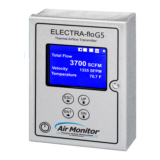
Application tagging information is at the bottom of the screen and is customer configurable. 1050 Hopper Ave, Santa Rosa, CA 95403 • Tel (800) AIRFLOW • www.airmonitor.com amcsales@airmonitor.com ELECTRA-flo G5 Transmitter Thermal Airflow & Temperature Measurement System 1015-3 - 07/18... -
Page 25: Analog Output Signals
3.8 ANALOG OUTPUT SIGNALS Airflow: Available on connector J1, terminals AO1+ and AO1- or AO2+ and AO2-. The full scale output is equal to Max Flow as programmed into the ELECTRA-flo G5 transmitter on the Flow Configuration sub-menu. Temperature: Available on connector J1, terminals AO1+ and AO1- or AO2+ and AO2-. The temperature analog output has a fixed scale of -20º... -
Page 26: Warranty
The warranty set forth above is in lieu of all other warranties either express or implied and constitutes the full extent of Air Monitor Corporation’s liability to the customer, or any other party, for breach of warranty.
Need help?
Do you have a question about the ELECTRA-flo G5 and is the answer not in the manual?
Questions and answers