Table of Contents
Advertisement
Quick Links
Air Monitor Corporation
116-045-10.P65 (6/99)
Installation, Operation,
and Maintenance Manual
VELTRON DPT 2500
Ultra-Low Range Differential
Pressure & Flow Transmitter
Installation, Operation & Maintenance
Air Monitor Corporation provides complete
technical support between the hours of
7 a.m. and 5 p.m. PST, M-F
Contact our Service Department
Toll Free: 1-800-AIRFLOW
or fax us at 1-707-526-2825
VELTRON DPT 2500
- IO&M Manual
Advertisement
Table of Contents

Related Manuals for Air Monitor VELTRON DPT 2500


Summary of Contents for Air Monitor VELTRON DPT 2500
- Page 1 Maintenance Manual VELTRON DPT 2500 Ultra-Low Range Differential Pressure & Flow Transmitter Installation, Operation & Maintenance Air Monitor Corporation provides complete technical support between the hours of 7 a.m. and 5 p.m. PST, M-F Contact our Service Department Toll Free: 1-800-AIRFLOW...
-
Page 3: Table Of Contents
TABLE OF CONTENTS VELTRON DPT 2500 TABLE OF CONTENTS INSTRUMENT WARRANTY ............................i SECTION 1 – GENERAL INFORMATION DESCRIPTION ..............................1 SECTION 2 – PERFORMANCE SPECIFICATIONS TRANSMITTER ............................... 2 OUTPUTS ................................. 2 POWER ................................2 MATERIALS OF CONSTRUCTION ......................... 2 SECTION 3 –... -
Page 5: Instrument Warranty
This document contains confidential technical data, including trade secrets and proprietary information which are the sole property of Air Monitor Corporation. The use of said data is solely limited to use as specified herein. Any other use is strictly prohibited without the prior written consent of Air Monitor Corporation. -
Page 6: Section 1 - General Information
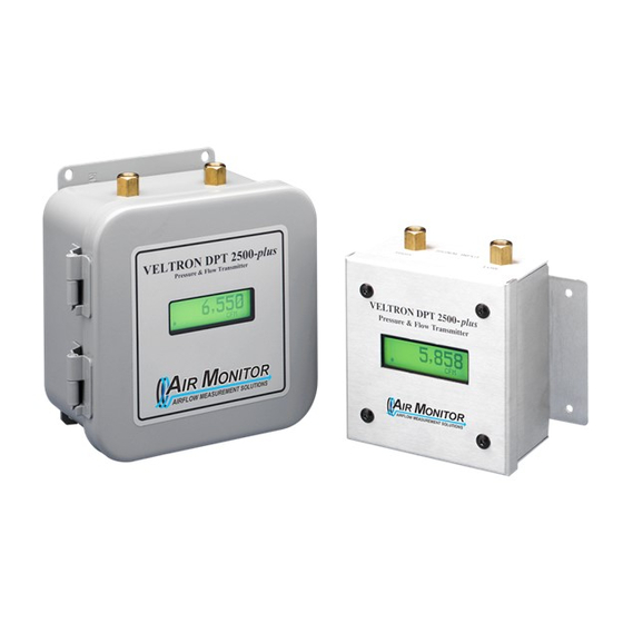
An optional integral LCD digital display provides local indication of the measured process in appropriate engineering units (in w.c., CFM, FPM, %, etc.). The VELTRON DPT 2500 is available in a NEMA 1 brushed aluminum enclosure with external wiring connections (Standard version) or a NEMA 12 painted steel enclosure with internal wiring connections (Industrial version). -
Page 7: Section 2 - Performance Specifications
VELTRON DPT 2500 SECTION 2 – PERFORMANCE SPECIFICATIONS 2 – PERFORMANCE SPECIFICATIONS 2.1 – TRANSMITTER 2.2 – OUTPUTS Output Signal. Pressure Spans Velocity Spans 4.0 to 20.0 mADC (2 wire). Proportional and linear to 0 to 0.10” w.c. 0 to 1266 fpm differential pressure or velocity 0 to 0.25”... -
Page 8: Section 3 - Installation
If not, contact Air Monitor’s Service Department at 1-800-AIRFLOW for further guidance. 3.2 – LOCATION • The standard version of the VELTRON DPT 2500 is a NEMA 1 enclosure suitable for most clean indoor locations. If additional protection is required, mount unit in an enclosure with adequate NEMA rating. -
Page 9: Mounting
• Tools Required: Electric drill; #25 (0.1495”) bit; screwdriver or nutdriver; and four #8-32 self-tapping machine screws. • The VELTRON DPT 2500 can be mounted in any position provided it is secured using all four mounting holes. • Reasonable consideration should be given to clearances for pressure and electrical connections. -
Page 10: Process Connections
The VELTRON DPT 2500 comes standard with brass ¼” tube compression fittings (or special fittings if ordered). To these fittings connect the appropriate rigid or flexible tubing. Although any size tubing can be used, the response time of the VELTRON DPT 2500 to process change can increase if there is an increase in tubing size or an increase in tube length. -
Page 11: Power/Signal Connections
3.5 – POWER/SIGNAL CONNECTIONS All wiring is done at the terminal strip of the VELTRON DPT 2500. The cover needs to be opened or removed to gain access to the terminal strip. On the industrial version, the signal/power wires need to be routed through the conduit connection on the bottom side of the enclosure. -
Page 12: Section 4 - Operation
1. Open or remove the cover on the VELTRON DPT 2500 and locate the jumper strip-J6 (see Figure 4) on the main board. 2. The factory setting for the filter is 0.50 seconds (jumper position 2). To slow the unit’s response time, remove the jumper and install on the pair of pins labeled 1.0 seconds (jumper position 3). -
Page 13: Section 5 - Calibration
DPT 2500 output and optional display. The VELTRON DPT 2500 can be calibrated mounted in its operating location or at a test bench in a calibration lab. If calibrated at a test bench, position the unit in the same attitude as in its operating location. -
Page 14: Transmitter Input Calibration
Connect DMM, set to read to the nearest 0.001 VDC, across test points TP0 COM (black) and TP1 XMIT 1 (brown) on the main circuit board. See Figure 4. With zero input pressure to the VELTRON DPT 2500, verify the DMM reads 0.000 ± 0.001 VDC. If adjustment is required, adjust XMIT ZERO (R37 on main circuit board) as needed. - Page 15 Place zeroing valve to the Normal position and apply input pressure (as read on manometer) to the Low port of the VELTRON DPT 2500. Adjust pressure to the positive equivalent of the minimum (negative) span value as indicated on the label under “SPAN”.
-
Page 16: Section 6 - Maintenance
SECTION 6 – MAINTENANCE 6 – MAINTENANCE The VELTRON DPT 2500 is a solid state device having few mechanical parts requiring special periodic maintenance. The following maintenance steps are not requirements, but guidelines for establishing a maintenance program for your specific installation. -
Page 17: Section 7 - Customer Service
Authorization with shipping instructions will be sent via facsimile. Equipment to be returned to Air Monitor should be returned in its original shipping container if possible. If this is not possible, ensure equipment is packaged sufficiently to protect it during shipment. - Page 18 VELTRON DPT 2500 APPENDIX A APPENDIX A FACTORY SET-UP SHEETS FACTORY SET-UP SHEETS WERE PROVIDED SEPARATELY VELTRON DPT 2500 Air Monitor Corporation - IO&M Manual 116-045-10.P65 (6/99)
Need help?
Do you have a question about the VELTRON DPT 2500 and is the answer not in the manual?
Questions and answers