Advertisement
Quick Links
Advertisement

Related Manuals for Linear AT71-250

Summary of Contents for Linear AT71-250
- Page 1 Linear Industries, Inc. AT71-250 Owner’s Manual February 2013...
- Page 2 IT IS VERY IMPORTANT TO READ THIS MANUAL PRIOR TO OPERATION OF THIS TRANSMITTER! Notice 1 The transmitter main operating voltage setting is marked on the rear of the AT71-250 chassis. Notice 2 The transmitter operating frequency is set from the factory.
- Page 3 ELECTRONIC EQUIPMENT. THE INSTALLATION, OPERATION, AND MAINTENANCE OF THIS EQUIPMENT INVOLVE RISKS TO PERSONNEL AND ALSO TO THE EQUIPMENT. LINEAR, INC. SHALL NOT BE RESPONSIBLE FOR INJURY OR DAMAGE THAT IS THE RESULT OF IMPROPER PROCEDURES OR USE BY INDIVIDUALS IMPROPERLY TRAINED OR LACKING THE KNOWLEDGE TO PERFORM ASSOCIATED TASKS.
- Page 4 Returns and Exchanges Equipment (Damaged or undamaged) should not be returned unless written approval and a Merchandise Return Authorization (MRA Number) is received from your Linear Sales representative or Linear Customer Service. Special shipping instruction will be provided which will assure proper handling. The circumstances and reasons for the return must be included in the request for return.
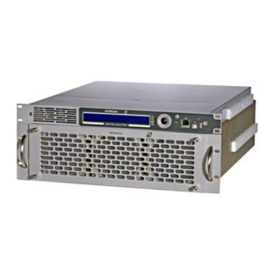
- Page 5 All operations of the AT71-250 is carried-out through a keypad and digital display, located on the front panel, including access to all the readings, alarms and configurations.
- Page 6 AT71-250 Transmitter Owner’s Manual Figure 2: AT72-250 - Rear View Figure 3 - AT71-250 - Block Diagram © Linear Industries, Inc. All Rights Reserved 6/38...
- Page 7 Low noise, variable speed fans for the air cooling system. Modular design, built with SMD (Surface Mounted Devices), easing the maintenance and service. Outstanding overall field system performance. 19” rack cabinet. © Linear Industries, Inc. All Rights Reserved 7/38...
- Page 8 Oscillator) at 10MHz reference, or an equivalent one external reference, e.g. a GPS signal. The on-channel modulated signal is routed to the RF amplifier, a class A highly linear amplifier with enough head room to accommodate future signal amplitude expansion during the non-linear pre-correction process.
- Page 9 The AT8001 is factory-set in one of four (4) optional versions. Depending upon the version it is possible set the operation with 2 types of non-linear pre-correction, mask filter equalization and/or ATSC set of 13 measurements on the RF signal demodulated.
- Page 10 (+50V nominal) and the electrical instantaneous current values in Ampere. The normal mains value for all power supplies is 208Vac. The three different models present on this transmitter are: 5. AT71-250 - 250W UHF ATSC/8VSB Transmitter - Technical Specifications Electrical Main 120 VAC, bi phase, 50-60 Hz.
- Page 11 AT71-250 Transmitter Owner’s Manual Annex A – AT71-250 Operational Software 1. Introduction The DTV transmitter AT71-250 provisions: (a) measurements, (b) configurations, (c) alarms, and (d) remote control via microcontrollers. Below is a detailed description about the operational software (configuration and operation) system installed in the AT71-250, located within the AT8001 exciter.
- Page 12 PAST ALARM – Alarm log screen. 3. Initialization: The first screen that appears when powering ON the transmitter is: Linear Industries Inc. AT7001 – ATSC 8VSB Digital Exciter Channel: ___ Output Power: _ __._ [W] DD/MM/YY HH:MM:SS © Linear Industries, Inc. All Rights Reserved 12/38...
- Page 13 Indicate the communication status among the RF COMMUNICATION STATUS drawer and the MASTER Control Unit. +15V voltage power supply measurement POWER SUPPLY + 8V voltage power supply measurement MEASUREMENTS +15V voltage battery measurement Battery © Linear Industries, Inc. All Rights Reserved 13/38...
- Page 14 Hit key “3” to view the other screens that are part of this menu. Transmitter Power Measurements : [2100] Programmed: Forward: ____ [W] Reflected: ____ [W] ALC Reference Voltage : __.____ [V] Hit ESC key to return to the prior screen. © Linear Industries, Inc. All Rights Reserved 14/38...
- Page 15 Select Transport Stream and hit ENTER Transport Stream Measurements: [2200] Transport Stream : Data Packets Rate : Null Packets Rate : FIFO Occupation (%): Hit ESC key to return to the prior screen. © Linear Industries, Inc. All Rights Reserved 15/38...
- Page 16 Mod. 2 I2: __._ A Mod. 3 I1: __._ A Mod. 3 I2: __._ A Mod. 4 I1: __._ A Mod. 4 I2: __._ A Excit. I1: __._ A Excit. I2: __._ A © Linear Industries, Inc. All Rights Reserved 16/38...
- Page 17 +27V : Fail Use the Up and Down keys, 1 and 3, to check the voltage status on the DTV exciter. To return to the Main Menu press ESC key. © Linear Industries, Inc. All Rights Reserved 17/38...
- Page 18 Measurements : [2000] Power Transport Stream Drawer Exciter Power Supply Communication Status -> Power Supply Select Power Supply and press ENTER Power Supply Measurements : [2600] 15V : OK Battery: 12.5 [V] © Linear Industries, Inc. All Rights Reserved 18/38...
- Page 19 -> Current Alarms Alarm Log Drawer Alarms Clear Alarm Log Select Current Alarms and press ENTER Current Alarms: [3100] Alarm List Empty! The “Alarm List Empty!” means the alarm is no longer present. © Linear Industries, Inc. All Rights Reserved 19/38...
- Page 20 The Clear Alarm Log if selected, erases the alarm log registers and then registers on the date and time when the registers were erased. On the table below is shown all possible alarms, generated on the Digital Exciter and the associated suggested action to cease its occurrence. © Linear Industries, Inc. All Rights Reserved 20/38...
- Page 21 [3000]. Main Menu : [0000] Setup Menu Measurements -> System Alarms/Log Remote Access Select System Alarms/Log and ENTER System Alarm/Log [3000] Current Alarms Alarm Log -> Drawer Alarms Clear Alarm Log © Linear Industries, Inc. All Rights Reserved 21/38...
- Page 22 Reduces the LO undesirable spurious Pre-Correction Enable and Disable the pre-correction circuitry Pilot Level Adjust the pilot level [ -2.048 ~ +511] Time and Date Setup Set time and date Password Setup Password configuration © Linear Industries, Inc. All Rights Reserved 22/38...
- Page 23 To reach the desirable output power level, press the key (2), to increase the power or (4) to decrease the power. Once the desirable power level is adjusted, press ENTER for software acknowledgement, otherwise the change will not become effective. © Linear Industries, Inc. All Rights Reserved 23/38...
- Page 24 [1200] Channel : -> Offset Model Select Offset and press ENTER Frequency Offset Adjustment: [1220] Frequency Offset: +__.____kHz The offset can be configured within 1Hz steps, in a ± 65536 Hz scale. © Linear Industries, Inc. All Rights Reserved 24/38...
- Page 25 The amplitude values are shown in dB, and the phase related values ar shown in degress. Image Frequency Suppression: [1300] -> I Amplitude : [dB] Q Amplitude: [dB] ◦ I Phase ◦ Q Phase © Linear Industries, Inc. All Rights Reserved 25/38...
- Page 26 [1300] -> I Offset : [mV] Q Offset: [mV] Using the keys, it’s possible to activate or deactivate the linear and non-linear pre-correction. ON: Activate Pre-correction OFF: Deactivate Pre-correction 7.5 Pre-correction adjustment Press ESC to return to the Setup Menu.
- Page 27 -2048 to +511. Press ESC up to the SETUP MENU screen. Setup Menu : [250] Power Setup Frequency Setup Image Frequency Suppression LO Leakage Suppression Pre-Correction -> Modulation Settings Time and Date Setup Password Setup Transmitter Setup © Linear Industries, Inc. All Rights Reserved 27/38...
- Page 28 1 and 3 keys increase or decrease the numerical value of the chosen position. Once you reach this screen, it is just possible to leave it after the password be choose. Please follow the sequence below for a complete understanding of the password setup process. © Linear Industries, Inc. All Rights Reserved 28/38...
- Page 29 Can be monitored on two possible ways: Via Front Panel – Local access via LCD screen and keypad, as shown on this section, it is possible configure, change functions and monitor performances. © Linear Industries, Inc. All Rights Reserved 29/38...
- Page 30 Press ESC up to the Remote Access screen 3000] Remote Access: IP Address -> Subnetwork Mask Gateway Select Subnetwork Mask and press ENTER Subnetwork Mask: [4200] 192.168.100.018 Configure the Mask using the keys 1 or 3 2 or 4. © Linear Industries, Inc. All Rights Reserved 30/38...
- Page 31 Press ESC up to the Remote Access screen Remote Access: [3000] IP Address Subnetwork Mask -> Gateway Access Gateway and press ENTER Gateway: [4300] [4300] 192.168.100.018 3 and 2 Configure the gateway address using © Linear Industries, Inc. All Rights Reserved 31/38...
- Page 32 AT71-250 Transmitter Owner’s Manual 300W UHF ATSC Power Amplifier Drawer Model GV4790 Functional Description The drawer GV 4790 is a UHF broadband power amplifier unit, air-cooled, designed to provide up to 300 Wrms ATSC. © Linear Industries, Inc. All Rights Reserved 32/38...
- Page 33 The second stage is also composed by two transistors named MRFE6S9060N also connected in quadrature. This module has built in a circuit for reading the temperature. The reading is sent to the control circuitry via software. © Linear Industries, Inc. All Rights Reserved 33/38...
- Page 34 MRF6VP3450H. This module has a highly linear RF transfer characteristic. The module has 2 sets of assembled components, the kit named CIM 3753 and the polarization circuitry kit named CIP 8592, and the CIM 3759 and CIP 8619 for also polarization and for temperature readings.
- Page 35 A directional coupler built in on the same hardware structure It also has a directional coupler circuit responsible for providing a sample of the signal after the amplification before the output mask filter. The RF signal out from this sample is intended to be used as a RF sample for the non-linear pre- correction system.
- Page 36 Digital and Analog measurements readings. d. Adjustments for the idle currents over the RF power transistors. e. Automatic stabilization of the idle currents on the RF power transistors. f. Automatic fan speed control. g. Checking alarms. © Linear Industries, Inc. All Rights Reserved 36/38...
- Page 37 The MOD CIM 3886 is composed of the following boards: - Card readings: CIM 3869 and CIP 8722 - Board DC / DC converter: CIM 3906 and CIP 8680 © Linear Industries, Inc. All Rights Reserved 37/38...
- Page 38 4790. The cooling system promotes circulation of air inside thereof. The front and back panels with ventilation holes also aid in refrigerating the transmitter, allowing direct exit of air from the device to the environment. © Linear Industries, Inc. All Rights Reserved 38/38...