
Related Manuals for Garmin Diamond DA 40


Summary of Contents for Garmin Diamond DA 40
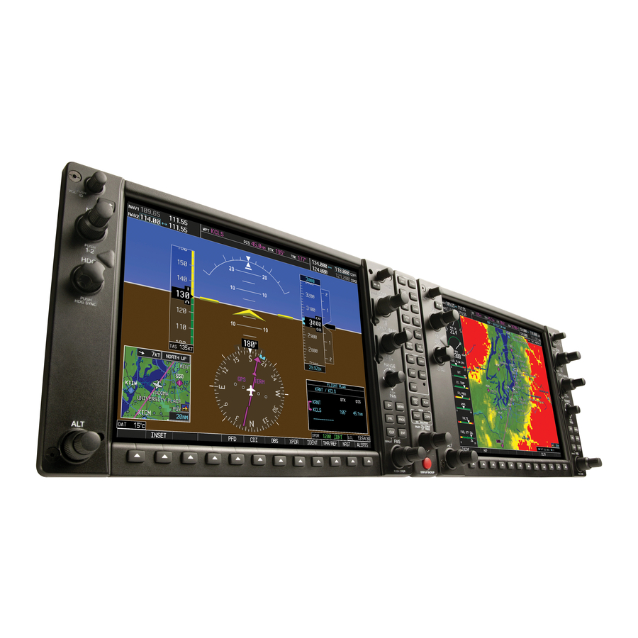
- Page 1 G1000 System Maintenance Manual Diamond DA 40 190-00303-03 January 2007 Revision 6...
- Page 2 Garmin. Garmin hereby grants permission to download a single copy of this manual and of any revision to this manual onto a hard drive or other electronic storage medium to be viewed and...
- Page 3 This Notice is being provided in accordance with California's Proposition 65. If you have any questions or would like additional information, please refer to our web site at www.garmin.com/prop65. CAUTION The GDU 1040s use a lens coated with a special anti-reflective coating that is very sensitive to skin oils, waxes and abrasive cleaners.
- Page 4 This page intentionally left blank. Page ii G1000/DA40 System Maintenance Manual Revision 6 190-00303-03...
-
Page 5: Table Of Contents
TABLE OF CONTENTS PARAGRAPH PAGE INTRODUCTION ......................1-1 ONTENT COPE URPOSE ..........................1-1 RGANIZATION .......................1-2 EFINITIONS BBREVIATIONS ......................1-3 EFERENCE UBLICATIONS ..........................1-3 ISTRIBUTION SYSTEM DESCRIPTION ......................2-1 QUIPMENT ESCRIPTIONS ........................2-8 QUIPMENT OCATIONS ....................2-9 EMOTE VIONICS NCLOSURE ....................2-11 LECTRICAL OWER ISTRIBUTION ....................2-12 IGHTNING TRIKE ROTECTION SPIDER G ........................2-16 ROUNDS... - Page 6 GEA 71 E ....................6-3 NGINE IRFRAME GTX 33 T .........................6-4 RANSPONDER GDC 74A A ....................6-4 OMPUTER GTP 59 OAT P ........................6-4 ROBE GRS 77 AHRS ..........................6-5 GMU 44 M ......................6-5 AGNETOMETER 6.10 & R .............6-6 ONFIGURATION ODULE EMOVAL EPLACEMENT 6.11 GEA 71 B &...
- Page 7 LIST OF ILLUSTRATIONS FIGURE PAGE Figure 2-1. G1000 / DA 40 Panel Installation ..................2-2 Figure 2-2. DA40 Panel (Rear View) .......................2-4 Figure 2-3. GTP 59 OAT Probe........................2-5 Figure 2-4. GRS 77 Mount ........................2-6 Figure 2-5. GMU 44 Installation.......................2-7 Figure 2-6. G1000 in DA 40 Equipment Locations..................2-8 Figure 2-7.
- Page 8 Figure 5-11. GDC 74A Data Paths ......................5-23 Figure 6-1. System Status Page (Configuration Mode) ................6-1 Figure 6-2. Configuration Module Installation ..................6-6 Figure 6-3. GEA Backshell Thermocouple....................6-7 Figure 7-1. G1000 Normal Mode Check ....................7-4 Figure 7-2. G1000 Reversionary Mode Check ..................7-4 Figure 7-3.
-
Page 9: Introduction
Section 2: System Description Provides a complete description of the type design change associated with installing the G1000 integrated cockpit system in the Diamond DA 40. An overview of the G1000 system interface is also provided. Section 3: G1000 Control & Operation Presents basic control and operation information specifically tailored to maintenance practices. -
Page 10: D Efinitions
Definitions/Abbreviations ADI: Attitude Display Indicator AHRS: Attitude Heading Reference System AMM: Airplane Maintenance Manual CDU: Control Display Unit CFR: Code of Federal Regulations EAU: Engine/Airframe Unit EIS: Engine Instrumentation Systems HIRF: High Intensity Radiated Fields HSDB: High-Speed Data Bus (Ethernet) IAU: Integrated Avionics Unit ICS:... -
Page 11: Table 1-1. Required Documents
Distribution This document is to be a permanent aircraft record and is distributed with a new G1000-equipped Diamond DA 40. Revisions to this document will be made by Garmin and will be distributed by Garmin per standard documentation revision procedures. - Page 12 This page intentionally left blank. Page 1-4 G1000/DA40 System Maintenance Manual Revision 6 190-00303-03...
-
Page 13: System Description
2.1.1 GDU 1040 MFD & PFD Two Garmin GDU 1040 CDUs are installed in the Diamond instrument panel. One is configured as a PFD and the other as a MFD (Configuration is determined by wiring harness). Both displays provide control and display of nearly all functions of the G1000 integrated cockpit system. The displays are located side-by-side with the GMA 1347 Audio Panel located in the middle (See Figure 2-1). -
Page 14: Figure 2-1. G1000 / Da 40 Panel Installation
Figure 2-1. G1000 / DA 40 Panel Installation Page 2-2 G1000/DA40 System Maintenance Manual Revision 6 190-00303-03... -
Page 15: Gea 71 Engine/Airframe Unit
2.1.2 GMA 1347 Audio Panel The Garmin GMA 1347 Audio Panel is a digital audio panel with integrated marker beacon receiver. The GMA 1347 provides control of all cockpit intercom/mic systems as well as NAV/COM/ILS audio. The unit also provides display reversion mode control through a large red button. -
Page 16: Figure 2-2. Da40 Panel (Rear View)
Figure 2-2. DA40 Panel (Rear View) Page 2-4 G1000/DA40 System Maintenance Manual Revision 6 190-00303-03... -
Page 17: Figure 2-3. Gtp 59 Oat Probe
2.1.7 OAT Probe The Garmin GTP 59 OAT Probe provides the GDC 74A with air temperature data. The OAT probe is mounted to the bottom starboard side of the DA 40 fuselage as shown in Figure 2-3. Figure 2-3. GTP 59 OAT Probe... -
Page 18: Figure 2-4. Grs 77 Mount
2.1.8 GRS 77 Attitude & Heading Reference System The Garmin GRS 77 AHRS provides attitude and heading information to the G1000 system. The unit is mounted remotely in the baggage compartment, to the starboard side of the remote avionics enclosure (see Figure 2-4 and Figure 2-6). -
Page 19: Figure 2-5. Gmu 44 Installation
2.1.9 GMU 44 Magnetometer The GMU 44 provides horizontal and vertical magnetic field information to the GRS 77 AHRS. This allows heading to be calculated and provides assistance during AHRS alignment. The GMU 44 is mounted beneath the starboard wing as shown in Figure 2-5 and Figure 2-6. Figure 2-5. -
Page 20: Figure 2-6. G1000 In Da 40 Equipment Locations
Equipment Locations GDC 74A GDC 74A Figure 2-6. G1000 in DA 40 Equipment Locations Page 2-8 G1000/DA40 System Maintenance Manual Revision 6 190-00303-03... -
Page 21: Figure 2-7. Remote Avionics Enclosure
Remote Avionics Enclosure A remote avionics enclosure allows LRUs to be inserted vertically, from above. The enclosure is also cooled with an avionics fan and duct assembly as shown in Figure 2-6 and Figure 2-7. The enclosure is installed as shown in Figure 2-7. The assembly is grounded to an existing grounding station using a field- fabricated aluminum ground strap. - Page 22 Figure 2-7. Remote Avionics Enclosure, Cont. Page 2-10 G1000/DA40 System Maintenance Manual Revision 6 190-00303-03...
-
Page 23: Figure 2-8. G1000/Da40 Electrical Distribution
Electrical Power Distribution Distribution of power to the G1000 occurs on three buses: Essential Bus: The ‘Essential’ bus is tied directly to the aircraft battery via the master switch. When the master switch is turned on, power is immediately supplied the ‘Essential’ bus. The ‘Essential’ bus is tied via a relay switch to the ‘Main’... -
Page 24: Figure 2-9. Tvs & Fuse Installation
Lightning Strike Protection The following modifications to the aircraft provide additional protection of G1000 equipment from the effects of lightning strike. 2.5.1 Alternator / Battery Voltage Suppressors & Fuses Two Transient Voltage Suppressors (TVS) are installed behind the instrument panel near the circuit . -
Page 25: Figure 2-10. Lightning Protection Components
2.5.2 GIA / AHRS Lightning Protection The GRS 77 and both GIA 63s are uniquely protected from the effects of lightning. A 0.499Ω resistor, a transient voltage suppressor, and a 3.2 Amp slow-blow fuse are used for each GIA and the AHRS. These components are installed on a field-fabricated aluminum block, which is mounted to the front of the remote avionics enclosure (see Figure 2-7 and Figure 2-10). -
Page 26: Figure 2-12. Component Wiring Diagram
Figure 2-12. Component Wiring Diagram Page 2-14 G1000/DA40 System Maintenance Manual Revision 6 190-00303-03... - Page 27 2.5.3 Lightning Strike Maintenance Proper electrical bonding of all metallic components is critical for the protection against the effects of lighting. Severe corrosion may inhibit a component’s ability to bond to the aircraft’s electrical ground plane. The following summarizes maintenance practices which are implemented to maintain adequate lightning protection for the aircraft.
-
Page 28: Figure 2-13. Spider Ground Installation
SPIDER Grounds Most G1000 connectors employ a SPIDER grounding system to provide necessary ground reference to shielding and/or transducers. A single 16-gauge wire is connected locally to the airframe. Additional ‘spider’ wires, 24-gauge, are used to connect shield grounds. The assembly is fastened directly to the backshell housing with two screws. -
Page 29: Figure 2-14. Map Sensor
Sensor Installations 2.7.1 Manifold Air Pressure A Kulite MAP sensor measures manifold air pressure. The sensor, manifold hose, and adapter fittings are installed as shown in Figure 2-14. Figure 2-14. MAP Sensor 2.7.2 Oil Pressure A Kulite pressure sensor measures oil pressure. The sensor, oil pressure hose, and fittings are installed as shown in Figure 2-15. -
Page 30: Figure 2-16. Oil Temperature Sensor
Figure 2-16. Oil Temperature Sensor 2.7.4 Fuel Pressure A Kulite pressure sensor is used to measure fuel pressure. The sensor, fuel hose, O-rings, and associated fittings are installed as shown in Figure 2-17. Figure 2-17. Fuel Pressure Sensor 2.7.5 Tachometer A tachometer provides engine RPM measurements to the G1000 system. -
Page 31: Figure 2-18. Tachometer Sensor
Figure 2-18. Tachometer Sensor 2.7.6 Fuel Flow A Shadin fuel flow sensor is used to measure fuel flow. The fuel flow sensor/fuel hose assembly is surrounded by a fire-resistant sleeve, as detailed in Figure 2-19 and Figure 2-20. The fuel flow/fire sleeve assembly is mounted to a field-fabricated bracket as shown in Figure 2-21. -
Page 32: Figure 2-20. Fuel Flow Assembled
Figure 2-20. Fuel Flow Assembled Figure 2-21. Fuel Flow Bracket Page 2-20 G1000/DA40 System Maintenance Manual Revision 6 190-00303-03... -
Page 33: Figure 2-22. Cht Probe
2.7.7 Cylinder Head Temperature Thermocouples Four thermocouples are used to measure cylinder head temperatures. A sensor is installed in each cylinder head. An example is shown in Figure 2-22. Figure 2-22. CHT Probe 2.7.8 Exhaust Gas Temperature Thermocouples Four thermocouples are used to measure exhaust gas temperatures. A sensor in installed in each exhaust header primary pipe. -
Page 34: Figure 2-24. Alternator Current Sensor Installation
2.7.9 Alternator Current Sensor A current sensor is used to measure alternator current output. The sensor is installed behind the circuit breaker panel as shown in Figure 2-24. Figure 2-24. Alternator Current Sensor Installation Page 2-22 G1000/DA40 System Maintenance Manual Revision 6 190-00303-03... -
Page 35: Figure 2-25. Flight Instrumentation Interface
G1000 System Communications 2.8.1 Flight Instrumentation The GRS 77 AHRS, GDC 74A Air Data Computer, and GMU 44 Magnetometer are responsible for providing the G1000 system with flight instrumentation. Data consists of aircraft attitude, heading, altitude, airspeed, vertical speed, and outside air temperature information, all displayed on the PFD (data is displayed on the MFD in reversionary mode only). -
Page 36: Figure 2-26. G1000 Engine/Airframe Interface
2.8.2 Engine Indicator System The GEA 71 provides engine/airframe data to the G1000 system. The unit interfaces to transducers shown in Figure 2-25 (see Section 2.1.4). Analog data is received from the transducers and is converted to digital signal by the GEA 71. Digital information is then sent through the primary RS-485 serial path to the #1 GIA 63. -
Page 37: Figure 2-27. G1000 Navigation/Communications
2.8.3 Communications/Navigation Systems The GIA 63 IAUs contain VHF COM, VHF NAV, and GPS receivers. COM and NAV audio is sent via digital audio to the GMA 1347 Audio Panel. GPS information is sent to the GRS 77 AHRS and both displays for processing assistance. The GTX 33 Mode S Transponder communicates with both GIAs. - Page 38 This page intentionally left blank. Page 2-26 G1000/DA40 System Maintenance Manual Revision 6 190-00303-03...
-
Page 39: Figure 3-1. Gdu 1040 Control Interface
G1000 Control & Operation All control and operation of G1000 equipment as normally used in flight occurs through the PFD, MFD and GMA 1347 audio panel. Figure 3-1 identifies various GDU 1040 buttons. Figure 3-2 identifies various GMA 1347 buttons. COM Frequency Toggle Key NAV Frequency... -
Page 40: Figure 3-3. G1000 Softkeys
User Interface 3.1.1 FMS Knob The FMS knob is the primary control for the G1000 system. Operation is similar to the Garmin 400/500 Series units. To cycle through different configuration screens: • To change page groups: Rotate the large FMS knob. -
Page 41: Figure 3-4. Normal Mode
G1000 Normal Mode To start the G1000 system in Normal Mode: 1. Turn on the master switch. The following G1000 equipment is powered on: GDU 1040 PFD & MFD (MFD receives power only if ‘Essential Bus’ switch is OFF) • GRS 77 AHRS •... -
Page 42: Figure 3-5. Mfd Failure Mode
Reversionary Mode Should a display communication or hardware failure occur, the G1000 system automatically enters the reversionary mode. The system reversionary mode forces the remaining display into showing all information related to safe flight. A manual reversionary mode also allows the operator to force the system into reversionary mode in situations where the system does not automatically enter reversionary mode. - Page 43 The G1000/DA 40 SW Loader Card part number defines all files specific to the G1000 system as installed in the DA 40. Refer to Appendix A for approved card part numbers. Approved Loader Card part numbers for the DA 40 can also be found in the Required Equipment List, Garmin P/N 005-00149-28.
- Page 44 3.4.2 Configuration Files A G1000/DA 40 SW Loader Card typically contains the following configuration files: AIRFRAME: This file contains data such as airspeed parameters, engine/airframe sensor • limitations, fuel tank parameters and alerting system settings that tailor a G1000 PFD or MFD to the DA 40.
-
Page 45: Figure 3-7. G1000 Lru Configuration File Storage
3.4.3 Configuration File Storage The G1000 system is designed to store all configuration settings in various places so that the configuration is retained in the aircraft during maintenance of units. Figure 3-7 and Figure 3-8 illustrate where the various configuration files are stored. Figure 3-7. -
Page 46: Figure 3-8. Grs/Gdc Configuration Settings Storage
The GRS 77 and GDC 74A configuration modules function differently than the rest of the system. The GDC 74A’s configuration file is loaded directly to GDC internal memory. A copy of the file is stored in the GDC configuration module. The GRS 77 configuration module does not store any configuration settings. -
Page 47: Figure 3-9. Set>Actv Diagram
In the first example shown in Figure 3-9, the SET columns do not match the ACTIVE columns. The inequality between SET and ACTIVE indicates a configuration mismatch. By pressing the SET>ACTV softkey, this copies the SET column to the LRU unit’s configuration memory. The settings then become the ACTIVE settings for the LRU being configured. -
Page 48: Figure 3-10. Loss Of Communication
When troubleshooting the system, technicians can look for inequalities between SET and ACTIVE columns. Certain problems can be resolved simply by pressing the SET>ACTV softkey, which reloads settings to the specific LRU from the PFD. (Note that this can also be accomplished by reloading the configuration files for the LRU, using the G1000 SW Loader Card. -
Page 49: Figure 3-13. Configuration Page Navigator
Using the FMS knob as described in Section 3.1.1 a user can navigate through different pages and page groups in the Configuration Mode. For complete description and breakdown of each page, refer to the G1000 Configuration manual, Garmin part number 190-00303-04. The following diagram shows the layout and organization of Configuration Mode page groups and pages. - Page 50 This page intentionally left blank. Page 3-12 G1000/DA40 System Maintenance Manual Revision 6 190-00303-03...
-
Page 51: G1000 Continued Airworthiness
G1000 Continued Airworthiness Airworthiness Limitations The G1000 integrated cockpit is airworthy when installed and configured in accordance the STC issued under FAA Project #ST3636WI-A. The Airworthiness Limitations section is FAA-approved and specifies maintenance required under §§ 43.16 and 91.403 of Title 14 of the Code of Federal Regulations, unless an alternative program has been FAA-approved. - Page 52 The remainder of this document is organized in the following fashion: Section 4.3 lists maintenance requirements related to the G1000 system. • Section 6 gives instructions regarding the removal and replacement of G1000 • equipment and parts. Section 7 gives configuration and testing instructions to be accomplished if G1000 •...
-
Page 53: Table 4-1. Required Maintenance
Maintenance Requirements The following table shows systems and items that must undergo tests or checks at specific intervals. If the interval is shown to be in flight time as well as calendar years, the first interval reached should be used as the limit. Table 4-1. -
Page 54: E Lectrical
Refer to Section 2.7.9 for installation drawing. On Condition Sensor Should one or both fuel quantity transducers fail, replace according to instructions in Diamond DA 40 Aircraft Fuel Tank Quantity Maintenance Manual. The new replacement fuel On Condition Sending Units quantity probe(s) must be re-calibrated according to the procedure set forth in Section 4.7. -
Page 55: Table 4-2. 1000 Hour Inspection Procedure
Table 4-2. Replace any damaged parts as required. Inspection may require the temporary removal of a unit or units to gain access to connectors. Follow guidance in Section 6 for equipment removal and replacement. Refer to the Diamond DA 40 Airplane Maintenance Manual for instructions on removing any access panels. - Page 56 Item Description/Procedure Initials Inspect remote avionics fan for dirt accumulation and other damage. Remove excess dirt as required. GIA Avionics Fan Ensure that the fan is operational. The GMU 44 is mounted below the starboard wing. Refer to Figure 2-5 and Figure 2-6 for the following inspection. Remove the three Phillips screws holding the GMU access plate to the wing.
- Page 57 Electrical Bonding Test The airframe bonding test is described in the DA40 AMM in Section 51-80-00 on Page 201. The following bonding test is provided for G1000-equipped DA 40 aircraft as a requirement beyond what is given in Section 51-80-00. 4.6.1 Requirements All G1000 equipment must be installed.
- Page 58 Fuel Tank Probe Re-Calibration The fuel tank quantity probes are calibrated at the aircraft factory to ensure their measuring accuracy. Should either fuel tank probe fail and require replacement, the new probe(s) must be calibrated by performing the following procedure. 1.
- Page 59 7. Press the L RESET softkey. Press ENTER to acknowledge the following prompt: 8. Ensure that the CAL VAL indication for the Left 1 Sub-Tank is stable. 9. Press the L EMPTY softkey. 10. Press the R RESET softkey. Press ENTER to acknowledge the following prompt: 11.
- Page 60 16. Record ‘5 gallon’ CAL VAL indications for both Right 1 and Left 1 Sub-Tanks in the tables above. The CAL VAL values should fall between 4 and 6 gallons as shown in the following examples: a) If both CAL VAL values fall within the specified ranges, the calibration is finished. b) If any CAL VAL value is outside of the specified ranges, perform the full-tank calibration procedure in Section 4.7.1.
- Page 61 The GRS 77 utilizes an Earth magnetic field model which is updated once every five years. The update is expected to be available from Garmin in each of the following years: 2005, 2010, 2015, and every five years thereafter, so long as the GRS 77 remains a Garmin-supported product.
- Page 62 This page intentionally left blank Page 4-12 G1000/DA40 System Maintenance Manual Revision 6 190-00303-03...
-
Page 63: Figure 5-1. System Status Page (Aux Group Normal Mode)
TROUBLESHOOTING This section provides instructions and guidance for G1000 system troubleshooting, as installed in the Diamond Model DA 40. IMPORTANT Sections 6, 7 and 8 provide detailed instructions on equipment removal, replacement, configuration, and return-to-service testing. Anytime a G1000 component or LRU is removed, swapped, or replaced, the technician must follow the procedures given in Sections 6, 7 and 8 to ensure proper operation of the system. -
Page 64: Figure 5-2. Alerts & Annunciations
G1000 Alerting System System Annunciations Annunciation Window Alerts Window Alerts Softkey Annunciation Figure 5-2. Alerts & Annunciations The G1000 Alert System conveys alerts to the pilot using combinations of the following features: Annunciation Window: The Annunciation Window displays abbreviated annunciation text. The Annunciation window is located to the right of the Altitude and Vertical Speed windows on the display. -
Page 65: Figure 5-3. Warning Softkey Annunciation
The G1000/DA 40 Alert System uses three levels: WARNING: This level of alert requires immediate pilot attention. A warning alert is accompanied by an annunciation in the Annunciation Window. Warning alert text appearing in the Annunciation Window is always RED. A warning alert is also accompanied by a flashing WARNING softkey annunciation, as shown in Figure , along with a continuos aural tone. -
Page 66: Figure 5-6. System Annunciations
System Annunciations If data fields become invalid due to an LRU failure, the PFD/MFD typically annunciates the failure with a large red X, as shown in Figure 5-6. No. 1 GIA 63 No. 1 GIA 63 No. 2 GIA 63 No. - Page 67 The following table provides basic troubleshooting guidance for LRU failures: Associated Invalid Data Field Solution LRU(s) • Check configuration settings for GIA1 and the PFD. NAV1 & COM1 Check Ethernet interconnect from GIA1 to the PFD. GIA1 Switch GIA1 and GIA2, to verify location of problem: If problem follows unit, replace defective unit.
- Page 68 Associated Invalid Data Field Solution LRU(s) ATTITUDE FAIL Check GRS ARINC 429 configuration settings for the PFD, MFD, GIA1, and GIA2. GRS 77 Replace defective GRS 77. HDG FAIL Replace the GMU 44 with a known good unit: GRS 77 & GMU 44 If problem persists, replace defective GRS 77.
- Page 69 The following table provides guidance for troubleshooting individual engine/airframe sensor failures. Be sure to also follow previous guidance given for the GEA 71. The technician should troubleshoot to isolate the fault by checking sensor-to-GEA wiring, replacing the suspect sensor, and finally by replacing the GEA 71. Replace one part at a time. Refer to Section 7.4.3 to check for correct operation of the sensors and GEA 71 after any part has been replaced.
- Page 70 DA 40-Specific Alerts The following alerts are configured specifically for the DA 40: WARNING Alerts: Annunciation Alert Message Solution Window • Check alternator current sensor for proper operation. Alternator failed. Battery is If current sensor is OK, troubleshoot alternator & aircraft ALTERNATOR only elec.
- Page 71 MESSAGE ADVISORY Alerts Message Advisory Solution PFD FAN FAIL – The cooling fan for the PFD is Ensure that the CDU FAN and/or AV FAN circuit breakers are inoperative. closed. MFD FAN FAIL – The cooling fan for the MFD is Check cooling fan wiring.
- Page 72 MFD1 COOLING – has poor MFD1 has exceeded its operating Replace the MFD. cooling. Reducing power usage. temperature range. If problem persists contact Garmin. Check PFD Fan for proper operation. PFD1 COOLING – has poor The PFD has exceeded it’s Replace the PFD.
- Page 73 5.5.5 Miscellaneous Alerts Failure Message Cause Solution Check the System Configuration page: Ensure that MFD1 and PFD1 are green. If configuration is not correct, reconfigure the PFD and MFD per instructions in Section A communication error has 7.1.2. XTALK ERROR – A flight display occurred between the MFD and cross talk error has occurred.
-
Page 74: Figure 5-7. Gma 1347 Data Paths
GMA Alerts Failure Message Cause Solution GMA1 SERVICE – GMA1 needs The system has determined that service. Return unit for repair. the GMA 1347 needs service. Replace GMA 1347. GMA1 FAIL – GMA1 in The system has detected a failure inoperative. - Page 75 GIA 63 Troubleshooting 5.7.1 Symptom Recommended Action Check COM antenna and cabling. Switch GIA1 and GIA2, to identify whether the unit or connectors/wiring is at Weak COM transmit power fault (Both GIAs must be configured when swapped, see Section 7.3.2): If problem follows unit, replace defective unit per Section 6.3.
-
Page 76: Gia Alert
GIA Alert Messages 5.8.1 COM Alerts Failure Message Cause Solutions COM1 SERVICE – COM1 needs The system has determined Replace GIA1 according to instructions in service. Return unit for repair. COM1 needs service. Section 6. COM2 SERVICE – COM2 needs The system has determined Replace GIA2 according to instructions in service. - Page 77 COM Related Alerts, Continued Failure Message Cause Solutions Press the COM1 external remote transfer switch again to cycle its operation. Check COM1 external remote transfer switch and wiring. Switch GIA1 and GIA2, to identify whether The COM1 external remote the unit or connectors/wiring is at fault COM1 RMT XFR –...
- Page 78 5.8.2 NAV Alerts Failure Message Cause Solution NAV1 SERVICE – NAV1 needs The system has detected a failure Replace GIA1. service. Return unit for repair. in NAV1 receiver. NAV2 SERVICE – NAV2 needs The system has detected a failure Replace GIA2. service.
- Page 79 5.8.3 Glideslope Alerts Failure Message Cause Solution G/S1 SERVICE – G/S1 needs The system has detected a failure Replace GIA1. service. Return unit for repair. in G/S1 receiver. G/S2 SERVICE – G/S2 needs The system has detected a failure Replace GIA2. service.
- Page 80 Check Avionics Fan for proper operation. GIA1 COOLING – GIA1 over GIA1 has exceeded its operating Replace GIA1. temperature. temperature range. If problem persists contact Garmin. Check Avionics Fan for proper operation. GIA2 COOLING – GIA2 over GIA2 has exceeded its operating Replace GIA2. temperature.
-
Page 81: Figure 5-8. Gea 71 Data Paths
GEA Troubleshooting 5.9.1 GEA Alerts Failure Message Cause Solution MANIFEST – GEA1 software The system has detected an See Section 7 for GEA 71 Software mismatch. Communication incorrect software version loaded Load Procedure. Halted. in GEA 71. GEA1 CONFIG – GEA1 The system has detected a GEA See Section 7 for GEA 71 Configuration configuration error. -
Page 82: Figure 5-9. Gtx 33 Data Paths
5.10 GTX Troubleshooting 5.10.1 GTX Alerts Failure Message Cause Solutions MANIFEST – GTX1 software The system has detected an Reload software. See Section 7 for mismatch. Communication incorrect software version loaded GTX 33 Software Load Procedure. Halted. in GTX 33. XPDR1 CONFIG –... - Page 83 5.11 GRS 77/GMU 44 Troubleshooting 5.11.1 GRS Alerts Failure Message Cause Solutions MANIFEST – GRS1 software The system has detected an • Reload software. See Section 7 for mismatch. Communication incorrect software version loaded GRS 77 Software Load Procedure. Halted. in GRS 77.
-
Page 84: Figure 5-10. Grs 77 Data Paths
5.11.3 GRS Redundant Paths Failure Message Cause Solutions • Check ARINC 429 configuration settings at the GDU and GIA page groups: If configuration is not correct, reconfigure GDU or GIA as described in Section 7. BACKUP PATH – AHRS using The GRS 77 is using a backup Check wiring. -
Page 85: Figure 5-11. Gdc 74A Data Paths
5.12 GDC 74A Troubleshooting 5.12.1 GDC Alerts Failure Message Cause Solutions • MANIFEST – GDC1 software The system has detected an Reload software. See mismatch. Communication incorrect software version loaded Section 7 for GDC 74A Software Halted. in GDC 74A. Load Procedure. - Page 86 This page intentionally left blank. Page 5-24 G1000/DA40 System Maintenance Manual Revision 6 190-00303-03...
-
Page 87: Figure 6-1. System Status Page (Configuration Mode)
G1000 Equipment Removal & Replacement This section describes how to remove and replace G1000 equipment in the Diamond DA 40. After removal and replacement, LRUs must be configured and tested as described in Section 7. CAUTION When removing and/or replacing any G1000 component, always ensure that aircraft power is off. - Page 88 GDU 1040 MFD & PFD Removal: 1. Using a 3/32 hex tool, rotate all four ¼-turn fasteners counter-clockwise until they reach their stops. 2. Carefully remove the display from the panel. 3. While supporting the display, disconnect the connector. Replacement: 1.
- Page 89 GIA 63 Integrated Avionics Units Removal: 1. Remove the baggage compartment cover to gain access to the remote avionics enclosure. 2. Remove the remote avionics enclosure cover. Removal process is identical for GIA #1 or #2. Remove and replace only one GIA 63 at a time. 3.
-
Page 90: Gtx 33 Transponder
GTX 33 Transponder Removal: Remove the baggage compartment floor and compartment to gain access to the remote avionics enclosure. Unlock the GTX 33 handle by loosening the Phillips screw on the handle. Pull the handle upward to unlock the GTX 33. Gently remove the unit from the rack. Replacement: Visually inspect the connectors using a flashlight to ensure there are no bent or damaged pins. -
Page 91: Grs 77 Ahrs
GRS 77 AHRS Removal: 1. Remove baggage compartment floor, then remove the baggage compartment. 2. Disconnect the AHRS connector. 3. Remove the four Phillips thumbscrews with a screwdriver and set them aside. 4. Gently lift the GRS 77 from the mounting plate. (If the mounting plate is removed, the GRS 77 must be re-calibrated. -
Page 92: Configuration Module Removal & Replacement
6.10 Configuration Module Removal & Replacement Figure 6-2. Configuration Module Installation Removal: 1. Disconnect connector from LRU. 2. Remove 2 screws (8) from cover (7) and remove cover. 3. Unplug connector from configuration module (1). 4. Remove configuration module. Replacement: 1. -
Page 93: Gea 71 Backshell Thermocouple Removal & Replacement
6.11 GEA 71 Backshell Thermocouple Removal & Replacement Figure 6-3. GEA Backshell Thermocouple Table 6-1. Thermocouple Kit (011-00981-00) Item # Description Qty. Needed Garmin Part Number 3” Thermocouple, K type 925-L0000-00 Pins #22 AWG 336-00021-00 Screw 211-60234-08 Removal 1. Remove GEA 71 per Section 6.4. - Page 94 This page intentionally left blank. Page 6-8 G1000/DA40 System Maintenance Manual Revision 6 190-00303-03...
-
Page 95: G1000 Equipment Configuration & Testing
G1000 Equipment Configuration & Testing This section provides procedures to be followed after a piece of G1000 equipment is replaced. At the beginning of each LRU section, instructions are given to guide the technician for various removal/replacement scenarios. These instructions define necessary procedures to be followed for situations where original equipment was reinstalled as well as for situations where new equipment (new serial number) is installed. - Page 96 4. Activate the cursor and highlight ‘AIRFRAME’ in the FILE LIST field. 5. Press the LOAD softkey. 6. Select YES and press the ENT key to acknowledge the following prompt: 7. Monitor the status of the upload. When the upload is finished, press the ENT key to acknowledge the following confirmation: 8.
- Page 97 13. At the System Status page, activate the cursor and highlight ‘PFD1’ and ‘MFD1’ in the LRU window. 14. Verify that the part number and version of the software reported matches the data in Appendix A. 15. Continue to the Aviation Database Loading procedure. 7.1.3 Aviation Database Loading 1.
-
Page 98: Figure 7-1. G1000 Normal Mode Check
7.1.4 PFD/MFD Test 1. Allow displays to initialize for ~1 minute. 2. Check that all COM/NAV display fields are valid in the top corners of the display. For PFD: Check that attitude, heading, altitude, airspeed, vertical speed and OAT fields are valid within 2 minutes of power up. -
Page 99: Gma 1347 Audio Panel
GMA 1347 Audio Panel Original GMA 1347 Reinstalled No software/configuration loading or testing is required if the removed GMA 1347 is re-installed. Continue to the final return-to-service checks in Section 8. New GMA 1347 Installed If a new GMA 1347 (new serial number) is installed, the correct software and configuration files must be loaded to the unit. - Page 100 7.2.2 GMA 1347 Configuration 1. Insert the correct G1000/DA 40 SW Loader Card (see Appendix A) into top slot of PFD. 2. Start the G1000 system Configuration mode, if the system is not already in Configuration mode. 3. At the PFD, go to the Configuration Upload page using the FMS knob: 4.
-
Page 101: Figure 7-3. Marker Beacon Symbology
7.2.3 GMA 1347 Test Except for marker beacon operation, an in-aircraft checkout may be performed in the aircraft with known good microphone, headset, and speaker. Intercom System (ICS) Check: 1. Plug in headsets at each ICS position. 2. Ensure that the MAN SQ key is off (no light). 3. -
Page 102: Gia 63 Integrated Avionics Unit
GIA 63 Integrated Avionics Unit Original GIA 63(s) Reinstalled: No software or configuration loading is required if the removed GIA is re-installed in its original position (GIA1 and GIA2 in their original racks). Continue to the return-to-service checks in Section 8. Original GIA 63s Swapped: No software loading is required if the originally installed GIA units are re-installed in opposite positions (GIA1 and GIA2 in opposite unit racks). - Page 103 8. After the files finish loading, press ENT to acknowledge the following prompt: 9. View the SUMMARY field and verify that both GIA1 and GIA2 software loading is complete. 10. Highlight the GPS software file. Ensure that GPS1 and GPS2 appear in the LRU field as shown: 11.
- Page 104 7.3.2 GIA 63 Configuration Loading 1. Insert the correct G1000/DA 40 SW Loader Card (see Appendix A) into top slot of PFD. 2. Start the G1000 system in Configuration mode, if not already in Configuration mode. 3. Go to the Configuration Upload page using the FMS knob: 4.
-
Page 105: Figure 7-4. Gps Signal Status
11. Go to the System Status page. 12. Activate the cursor and highlight each of the following items in the LRU window: -GIA1 -GIA2 -GPS1 -GPS2 13. Check the reported part number/version of each software file and compare to the data in Appendix A. - Page 106 VHF COM Interference Test: This test must be conducted outside. Use of a GPS repeater inside a hangar may result in a failed test. This procedure assumes that the system is currently set to 25 kHz COM channel spacing. Once the signal acquisition test has been completed successfully, perform the following steps: 1.
- Page 107 VOR/LOC/GS Test: Check the VOR, ILS, and Glideslope functions with ramp test equipment. Operate the equipment according to the test equipment manufacturer’s instructions. Adjust the RF signal to a level adequate to perform the test. Select the appropriate HSI source by using the CDI softkey. NOTE The PFD HSI does not show a course deviation bar unless a valid VHF NAV frequency is tuned.
-
Page 108: Gea 71 Engine/Airframe Unit
GEA 71 Engine/Airframe Unit Original GEA 71 Reinstalled No software or configuration loading is required if the removed GEA 71 is re-installed. Continue to the return-to-service checks in Section 8. New GEA 71 Installed If a new GEA 71 (new serial number) is installed, the correct software and configuration files must be loaded to the unit. - Page 109 7.4.2 GEA 71 Configuration Loading 1. Insert the correct G1000/DA 40 SW Loader Card (see Appendix A) into top slot of PFD. 2. Start the G1000 system in Configuration mode, if not already in Configuration mode. 3. At the PFD, go to the Configuration Upload page using the FMS knob: 4.
-
Page 110: Figure 7-5. G1000 Engine/Airframe Indicators
7.4.3 GEA 71 Test All engine/airframe transducers must be checked to ensure proper operation. Restart both displays in normal mode. Figure 7-5. G1000 Engine/Airframe Indicators On the MFD, check the indication for each of the sensor or monitor inputs with the aircraft engine off. Observe the ‘Default’... -
Page 111: Gtx 33 Transponder
GTX 33 Transponder Original GTX 33 is Reinstalled No software or configuration loading is required if the removed GTX 33 is re-installed. Continue to the GTX 33 Test procedure. New GTX 33 is Installed If a new GTX 33 (new serial number) is installed, the correct software and configuration files must be loaded to the unit. - Page 112 7.5.2 GTX 33 Configuration Loading 1. Insert the correct G1000/DA 40 SW Loader Card (see Appendix A) into top slot of PFD. 2. Start the G1000 system in Configuration mode, if not already in Configuration mode. 3. At the PFD, go to the Configuration Upload page using the FMS knob: 4.
- Page 113 12. Select the GTX page group, then select the Transponder Configuration page on the PFD: 13. Ensure that the ‘ADDRESS TYPE’ is ‘US TAIL’ under the ‘SET’ and ‘ACTIVE’ columns. 14. Activate the cursor and highlight the ‘ADDRESS’ field. Use the small/large FMS knobs to enter the aircraft registration number.
- Page 114 7.5.3 GTX 33 Test Operation of the GTX 33 Mode-S transponder is accomplished using the G1000 PFD. Refer to Garmin part number 190-00324-00, G1000 for DA40 Cockpit Reference Guide, for basic operation. Perform a basic operational check on the transponder.
-
Page 115: Gdc 74A Air Data Computer
GDC 74A Air Data Computer Original GDC 74A is Reinstalled No software or configuration loading is required if the removed GDC 74A is re-installed. Continue to the GDC 74A Test procedure. New GDC 74A is Installed If a new GDC 74A (new serial number) is installed, the correct software and configuration files must be loaded to the unit. - Page 116 7.6.2 GDC 74A Configuration Loading 1. Insert the correct G1000/DA 40 SW Loader Card (see Appendix A) into top slot of PFD. 2. Start the G1000 system in Configuration mode, if not already in Configuration mode. 3. At the PFD, go to the Configuration Upload page using the FMS knob: 4.
- Page 117 7.6.3 GDC 74A Test Verification of the altimeter and airspeed must be performed using a pitot/static ramp tester. The static port and altimeter must be verified in accordance with Title 14 of the Code of Federal Regulations (CFR) § 91.411 and Part 43 Appendix E. The PFD must be in Configuration mode and the MFD must be in Reversionary mode for performing the tests as outlined in Part 43 Appendix E.
- Page 118 NOTE The following tests are above and beyond the requirements set forth in Appendix E. Pitot/Static Airspeed Test to simulate air speeds shown in the table below. Command the pitot/static ramp tester 2. Wait for to report that target values have been achieved. the ramp tester 3.
-
Page 119: Grs 77 Ahrs / Gmu 44 Magnetometer
GRS 77 AHRS / GMU 44 Magnetometer Original GRS 77 is Reinstalled If the original GRS 77 was reinstalled, then no software loading is required. Continue to the GRS/GMU Calibration section. New GRS 77 is Installed If the GRS 77 was replaced with a new unit (new serial number) then software must be loaded. Continue to the GRS 77 Software Loading procedure. - Page 120 8. After the files finish loading, press the ENT key to acknowledge the following prompt: 9. Check the SUMMARY field to ensure the load is ‘COMPLETE’. 10. Go to the System Status page. 11. Activate the cursor and highlight ‘GRS1 – GIA1’, then ‘GRS1 – GIA2’, and finally, ‘GRS1 FPGA’...
- Page 121 7.7.2 GMU 44 Software Loading: 1. Insert the correct G1000/DA 40 SW Loader Card (see Appendix A) into top slot of PFD. 2. Start the G1000 system in Configuration mode. 3. Go to the Software Upload page using the FMS knob. 4.
- Page 122 7.7.3 GRS/GMU Calibration GRS/GMU Recalibration Criteria Calibrations Required Procedure A: Procedure B: Procedure C: GRS 77 GRS/GMU Engine Run-up Condition Pitch/Roll Magnetic Vibration Offset Calibration Test None Required. GMU 44 was removed and reinstalled. (no change in serial number) Continue to GRS/GMU Test section. GMU 44 was replaced with new unit.
- Page 123 4. Ensure that the No. 1 GRS 77 is selected in the SELECT GRS UNIT window on the PFD. a) Activate the cursor and highlight the SELECT PROCEDURE window and select PITCH/ROLL OFFSET. b) Press the ENT key. c) Use the cursor to highlight the BEFORE CALIBRATION window. d) Follow the checklist items displayed on the PFD and press the ENT key as each step is completed or confirmed.
- Page 124 7.7.5 Procedure B: GRS/GMU Magnetic Calibration CAUTION CALIBRATION PROCEDURE B MUST BE CARRIED OUT ON A COMPASS ROSE IN ORDER TO GUARANTEE MEASUREMENTS FREE OF ENVIRONMENTAL MAGNETIC DISTURBANCES. ATTEMPTING TO CARRY OUT THIS MANEUVER ON A TYPICAL RAMP AREA MAY NOT YIELD A SUCCESSFUL CALIBRATION.
- Page 125 8. Activate the cursor and highlight the SELECT PROCEDURE window and select MAGNETOMETER. 9. Press the ENT button. 10. Use the cursor to highlight the BEFORE CALIBRATION window. 11. Follow the checklist items displayed on the PFD and press the ENT key as each one is completed or confirmed.
- Page 126 15. Repeat the turn-and-stop process until the PFD advises that a successful calibration is complete. The GRS 77 AHRS then enters its normal operational mode. Press the ENT button on the PFD to conclude this procedure. 7.7.6 Procedure C: Engine Run-Up Vibration Procedure Calibration Procedures A and B are not required prior to this procedure.
- Page 127 8. Initiate the AHRS engine run-up vibration test procedure by performing the following steps: a) Select the ENGINE RUN-UP TEST procedure and press the ENT key. b) Follow the checklist items displayed on the PFD, and press the ENT key as each step is completed or confirmed.
-
Page 128: Software /Configuration Troubleshooting
Software/Configuration Troubleshooting Problem Solutions GDU 1040 MFD or PFD displays do not power up • Ensure that the criteria listed in 7.8.1 are fulfilled for the applicable situation. • Ensure power is present at display connector. • Replace display. Software file load fails: •... - Page 129 7.8.1 System Communication Hierarchy The following criteria must be satisfied to be able to perform these desired operations: Desired Operation Criteria for Success • G1000/DA 40 SW Loader Card must be inserted in Load Software to GDU 1040 MFD or PFD Displays top slot for each display to be loaded.
-
Page 131: System Return To Service Procedure
System Return to Service Procedure This final checkout tests various secondary communications paths to ensure that the paths function correctly. Perform the following steps and verify the results of each test. GPS Failure Test Step Desired Result Single GPS Failure Conditions: GPS Failure –... -
Page 132: Gia Failure Test
GIA Failure Test Step Desired Result Single GIA Failure Conditions: GIA1 Failure – For a GIA1 failure, only the following shall flag invalid: Remove power from GIA1 by pulling COM1/NAV1 field (PFD & MFD). NAV/GPS1 and COM1 breakers. NAV1 CDI loses deviation bar (PFD only). Check for desired results. -
Page 133: Ahrs/Adc Backup Path Test
AHRS/ADC Backup Path Test Step Desired Result Secondary AHRS/ADC path check: The following shall occur on the MFD when power is removed from the PFD and GIA2: Remove power from PFD. MFD switches to reversion mode. Remove power from GIA2. Attitude and Heading remain valid from AHRS. -
Page 134: Flight Test
VOR receiver at the extents of a ground facility’s service volume. (FAA AC 23-8A) Maintenance Records After conducting the function check flight in accordance with the Diamond DA 40 Airplane Maintenance Manual, the aircraft may be returned to service. Record the following information in appropriate aircraft maintenance logs: Part number of the G1000/DA 40 SW Loader Card used to perform software loading or •... -
Page 135: Appendix A Installation Data
Appendix A Installation Data G1000 Equipment List The following table shows all available G1000 LRUs and compatible software versions/part numbers. Any time a software file is changed or reloaded, the part number and version must be checked against the following table for correctness. CODE LOADER SOFTWARE... -
Page 136: Additional Equipment Required
Additional Equipment Required Description Part Number Vendor Tachometer Sensor 494-00024-00 Alternator Current Sensor 494-00025-00 Garmin International 1200 E 151 Street Cylinder Head Temp Sensor 494-00026-01 Olathe, KS 66062 U.S.A. Exhaust Gas Temp Sensor 494-00026-00 TEL: 913-397-8200 Voltage Suppressors 682-00002-00 FAX: 913-3978282... -
Page 137: Parts List
Parts List G1000/DA40 System Maintenance Manual Page A-3 190-00303-03 Revision 6... - Page 138 Page A-4 G1000/DA40 System Maintenance Manual Revision 6 190-00303-03...
-
Page 139: Weight & Balance
Weight & Balance NOTE The GDL 69/69A are shown as provisions only. G1000/DA40 System Maintenance Manual Page A-5 190-00303-03 Revision 6... - Page 140 This page intentionally left blank Page A-6 G1000/DA40 System Maintenance Manual Revision 6 190-00303-03...
-
Page 141: Appendix B G1000 Software/Configuration Procedure
Appendix B G1000 Software/Configuration Procedure This section provides a complete software/configuration procedure for instances where the entire G1000 system software version is to be re-loaded and/or updated. The following diagram depicts an overview of the entire software/configuration sequence for the G1000 system. It should be noted that in some cases, not all LRU software versions are updated at the same time. -
Page 142: System Power Up
System Power Up Apply power to the G1000 by doing the following: 1. Turn on the BATT side master switch. 2. Turn on the ground power unit, if utilized. 3. Turn on the AVIONICS master switch. At this moment, all G1000 equipment is receiving power. B.1.1 System Software Verification Before loading any software files, the existing files are to be checked and verified against aircraft... -
Page 143: Mfd & Pfd Software Load
MFD & PFD Software Load 1. Remove power to the MFD and PFD by pulling the MFD and PFD circuit breakers. 2. Insert the correct G1000/DA 40 Card Loader (see Appendix A) into the MFD top card slot. 3. While holding the ENT key on the MFD, restore power by closing the MFD circuit breaker. 4. -
Page 144: Initial G1000 Configuration
Initial G1000 Configuration 1. At the PFD, go to the Configuration Upload page using the FMS knob. 2. Activate the cursor and highlight ‘AIRFRAME’ in the FILE LIST field. 3. Press the LOAD softkey. 4. Select YES and press the ENT key to acknowledge the following prompt: 5. -
Page 145: Gia Software Load
GIA Software Load 1. Go to the Software Upload page using the FMS knob. 2. Activate the cursor and select the GIA 63 software file. Verify that GIA1 and GIA2 appear in the LRU field as shown: 3. Press the LOAD softkey. 4. - Page 146 8. Highlight the GPS software file. Ensure that GPS1 and GPS2 appear in the LRU field as shown: 9. Press the LOAD softkey. 10. Select YES and press the ENT key to acknowledge the following prompt: 11. The software for GPS1 begins to load. GPS2 software loads immediately after GPS1 software finishes loading.
-
Page 147: Gia Configuration
GIA Configuration 1. Go to the Configuration Upload page using the FMS knob. 2. Activate the cursor and highlight GIA1 in the FILE LIST field. 3. Press the LOAD softkey. 4. Select YES and press ENT to acknowledge the following prompt: 5. -
Page 148: Final Lru Software Load
Final LRU Software Load 1. Go to the Software Upload page using the FMS knob. B.6.1 GMA 1347 Audio Panel Software 1. Highlight the GMA software file. Ensure that both paths to the GMA through GIA1 and GIA 2 appear in the LRU field as shown: 2. - Page 149 B.6.2 GDC 74A Air Data Computer Software 1. Highlight the GDC74 software file. Ensure that GDC to GIA data path appears in the LRU field as shown: 2. Press the LOAD softkey. 3. Select YES and press the ENT key to acknowledge the following prompt: 4.
- Page 150 B.6.3 GRS 77 AHRS Software 1. Highlight the GRS77 software file. Ensure that the GRS to GIA data path appears in the LRU field as shown: 2. Press the LOAD softkey. 3. Select YES and press the ENT key to acknowledge the following prompt: 4.
- Page 151 B.6.4 GMU 44 Magnetometer Software 1. Highlight the GMU44 software file. Ensure that GMU1 appears in the LRU field as shown: 2. Press the LOAD softkey. 3. Select YES and press the ENT key to acknowledge the following prompt: 4. The software for the GMU 44 Magnetometer begins to load. Monitor the upload status as it progresses: 5.
- Page 152 B.6.5 GTX 33 Transponder Software 1. Highlight the GTX33 software file. Ensure that both paths to the GTX 33 through GIA1 and GIA appear in the LRU field as shown: 2. Press the LRU softkey. Select the GTX1 - GIA1 data path to load software. Press the LOAD softkey.
- Page 153 B.6.6 GEA 71 Engine/Airframe Unit Software 1. Highlight the GEA7X software file. Ensure that both paths to the GEA 71 through GIA1 and GIA 2 appear in the LRU field as shown: 2. Press the LRU softkey. Select the GEA - GIA1 data path to load software. Press the LOAD softkey.
-
Page 154: Final Lru Configuration
Final LRU Configuration 1. Go to the Configuration Upload page using the FMS knob. 2. Activate the cursor. 3. Highlight the following LRUs in the FILE LIST field: a) GMA1 Press the LOAD softkey. Press ENT at the START CONFIGURATION UPLOAD prompt. iii. -
Page 155: Software Load Confirmation
Software Load Confirmation 1. Go to the System Status page using the FMS knob. Activate the cursor and highlight the LRU window. 2. Highlight each of the following items in the LRU window and verify that the reported software part number and version matches the information in Appendix A: -MFD1 -PFD1 -GIA1... -
Page 156: Aviation Database Loading
Aviation Database Loading 1. Remove power from the system. 2. Insert an aviation database update SD card into the top slot of the PFD. 3. Turn the G1000 system on. The following prompt is displayed in the upper left corner of the PFD: 4.
Need help?
Do you have a question about the Diamond DA 40 and is the answer not in the manual?
Questions and answers