Motorola DLR1060 User Manual
Hide thumbs
Also See for DLR1060:
- User manual (193 pages) ,
- Quick reference manual (42 pages) ,
- User manual (118 pages)
Table of Contents
Advertisement
Advertisement
Table of Contents

Subscribe to Our Youtube Channel
Related Manuals for Motorola DLR1060


Summary of Contents for Motorola DLR1060
- Page 1 Two-Way Radios User Guide DLR1020, DLR1060 models...
-
Page 3: Table Of Contents
About the Li-Ion Battery ... . . 12 CONTENTS Battery Recycling and Disposal ..13 Installing the Lithium-Ion Contents......1 (Li-Ion) Battery . - Page 4 Radio Status ......36 Motorola Limited Warranty for Advanced Radio Configuration ..37 the United States and Canada .
-
Page 5: Product Safety
For a list of Motorola-approved batteries and PRODUCT SAFETY other accessories, visit the following website which lists approved accessories: PRODUCT SAFETY AND RF www.motorolasolutions.com/DLR EXPOSURE COMPLIANCE Before using this product, read the operating instructions and RF energy awareness information contained in the Product... -
Page 6: Introduction
Thank you for purchasing the Motorola® DLR 8000 West Sunrise Boulevard Series Radio. This radio is a product of Plantation, Florida 33322 Motorola's 80 plus years of experience as a world leader in the designing and PACKAGE CONTENTS manufacturing of communications equipment. - Page 7 For a copy of a large-print version of this user guide or for product-related questions, contact 1-800-448-6686 in the USA 1-800-461-4575 in Canada 1-888-390-6456 on TTY (Text Telephone) For product related information, visit us at: www.motorolasolutions.com/DLR English...
-
Page 8: Fcc Licensing Information
Changes or modifications not expressly approved la FCC / IC pour opérer cette radio et ne devraient by Motorola may void the user’s authority granted pas être faits . Pour se conformer aux exigences by the FCC/IC to operate this radio and should not de la FCC / IC, les ajustements de l'émetteur... -
Page 9: Batteries And Chargers Safety
Use of accessories not recommended by To reduce risk of electric shock, unplug the Motorola may result in risk of fire, electric charger from the AC outlet before attempting shock, or injury. -
Page 10: Operational Safety Guidelines
OPERATIONAL SAFETY located at the bottom of the charger. GUIDELINES • Make sure that the cord is located where it will not be stepped on, tripped over, or subjected to • Turn the radio OFF when charging battery. water, damage, or stress. •... -
Page 11: Radio Overview
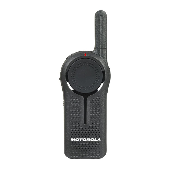
RADIO OVERVIEW PARTS OF THE RADIO Programmable Top Button Antenna Power Button Tx/Rx Audio Accessory Indicator Connector PTT (Push-To- Volume/Up-Down Talk) Button Control Buttons Menu Button Microphone Battery Speaker English... -
Page 12: Power Button
DLR Series comes with a Standard Capacity Microphone Li-Ion battery. Other batteries may be available. Speak clearly into the microphone when For more information, see “Battery Features” sending a message. on page 12. Antenna For models DLR1020 and DLR1060 the antennas are non-removable. English... - Page 13 The radio’s model is shown on the back of the radio and provides the following information: Table 1: DLR Series Radio Specifications Transmit Number of Frequency Model Power Antenna Band Channels (Watts) DLR1020 ISM 900 MHz Non-removable DLR1060 ISM 900 MHz Non-removable English...
-
Page 14: Battery Features
Motorola batteries are designed specifically to in future. be used with a Motorola charger and vice About the Li-Ion Battery versa. Charging in non-Motorola equipment may lead to battery damage and void the The DLR Series radio comes equipped with a battery warranty. -
Page 15: Battery Recycling And Disposal
1-800-8-BATTERY specific requirements and information in your This internet site and telephone number also area. Motorola fully endorses and encourages provides other useful information concerning the recycling of Li-Ion batteries. In the U.S. and recycling options for consumers, businesses Canada, Motorola participates in the and governmental agencies. -
Page 16: Installing The Lithium-Ion (Li-Ion) Battery
Installing the Lithium-Ion (Li-Ion) Battery Slide the latch at the top of the battery door to the unlock position and lift up the battery door at the center recess. Align the battery contacts with the tabs in the battery compartment. Insert the contact side of the battery first, then press the battery down to secure in place. -
Page 17: Removing The Lithium-Ion
Removing the Lithium-Ion (Li-Ion) Battery Turn OFF the radio. Slide the latch at the top of battery door to the unlock position and lift up the battery door at the center recess. Pull on the battery removal tab until battery is disengaged from battery compartment. Pull the battery away from radio. -
Page 18: Holster
Holster Power Supply, Adaptor and Drop-in Tray Charger Insert the radio into the base of the holster at an The radio is equipped with one Drop-in Tray angle. Press the radio against the back of the Charger and one Power Supply with Adaptor. holster until the hooks on the holster are For more information, refer to “Chargers”... -
Page 19: Battery Life Information
When the Battery Save feature is set to ON (enabled by default), the battery life lasts longer. The following table summarizes battery life estimations: Table 2: Li-Ion Battery Life with Tx Power 1 Watt for DLR1020 and DLR1060 Battery Type... -
Page 20: Charging The Battery
Drop-in Tray Charger. Plug the AC Adaptor into a power outlet. Insert the radio into the Drop-in Tray Single Unit Charger with the radio facing the Motorola logo on the charger as shown in the figure above. English... - Page 21 Note: When charging a battery attached to the Table 3: Motorola Authorized Batteries radio, turn the radio OFF to ensure a full charge. See “Operational Safety Guidelines” Part Number Description on page 8 for more information. Charging A Stand-Alone Battery...
-
Page 22: Drop-In Tray Charger Charge Status Indicators
Drop-in Tray Charger Charge Status Indicators Table 4: Charge Status LED Indicator LED Indication Charger State Charger Ready for Use Single Flash Green Waiting to Charge(*) Slow Flash Amber Battery Fault(**) Fast Flash Red Charging Steady Red Charged(***) Steady Green No Battery in Pocket LED Off (*) Battery temperature is too warm or too cold or wrong power voltage is being used. -
Page 23: Drop-In Tray Charger Battery State Of Charge Indications
Drop-in Tray Charger Battery State of Charge Indications Table 5: Battery State of Charge LED Indication Battery State of Charge Battery Low Flash Red 1 Time Battery Medium Flash Amber 2 Times Battery High Flash Green 3 Times If there is NO LED indication: Check if the radio with battery, or the battery alone, is inserted correctly. -
Page 24: Estimated Charging Time
Estimated Charging Time The following table provides the estimated charging time of the battery. For more information, see “Battery” on page 57. Table 6: Battery Estimated Charging Time Estimated Charging Time Charging Solutions Standard Battery Standard ≤ 3.50 Hours English... - Page 25 Charging a Radio and Battery using Place the Multi-Unit Charger on a flat surface. a Multi Unit-Charger - MUC (Optional Insert the power cord plug into the MUC’s dual Accessory) pin connector at the bottom of the MUC. Plug the power cord into an AC outlet. Turn the radio OFF.
-
Page 26: Multi-Unit Charger Charge Status Indicators
Multi-Unit Charger Charge Status Indicators Table 7: Charge Status LED Indicator LED Indication Charger State Charger Ready for Use Single Flash Green Waiting to Charge(*) Slow Flash Amber Battery Fault(**) Fast Flash Red Charging Steady Red Charged(***) Steady Green No Battery in Pocket LED Off (*) Battery temperature is too warm or too cold or wrong power voltage is being used. -
Page 27: Multi-Unit Charger Battery State Of Charge Indications
Multi-Unit Charger Battery State of Charge Indications Table 8: Battery State of Charge LED Indication Battery State of Charge Battery Low Flash Red 1 Time Battery Medium Flash Amber 2 Times Battery High Flash Green 3 Times If there is NO LED indication: Check if the radio with battery or the battery alone, is inserted correctly (refer to step 5 of "Charging a Radio and Battery using a Multi Unit-Charger - MUC (Optional Accessory)"... - Page 28 Notes English...
-
Page 29: Getting Started
volume beeps increment as the volume GETTING STARTED increases. For the following explanations, refer to “Parts Note: Do not hold the radio too close to the ear Of The Radio” on page 9. when the volume is high or when adjusting the volume TURNING RADIO ON/OFF There are 16 increments of volume. -
Page 30: Selecting A Channel
SELECTING A CHANNEL talkgroup when the Programmable Top Button is pressed. To select a channel, press Menu button until the voice announcement “Channel <Number>, Private Direct Call – Enters into Private Direct to change press + or -” is heard. Call mode with a pre-programmed radio user Press (+) or (-) buttons to select the desired channel. -
Page 31: Transmitting And Receiving
TRANSMITTING AND RECEIVING • Press the (+) button to increase the volume, or the (-) button to decrease the volume. • To receive, listen through the speaker. To respond, press the PTT (Push to Talk) and WAIT to hear the Talk Permit Tone (a quick Solid Red double beep) BEFORE you start speaking. -
Page 32: Private Reply Request
Private Reply Request Press button to queue up Privately reply to someone talking to a group by for private reply pressing the Programmable Top Button (while the person is still talking) in order for your Private Reply request to be queued. If your Private Reply request is successfully in queue, the Programmable Top Button starts blinking GREEN. - Page 33 talking). This time window is called "Group Programmable Top Button Hang Time" (check the CPS settings for more LED blinks GREEN when details). If you private reply within this Group queued up Hang Time, you can talk privately to the last user that was transmitting.
-
Page 34: Talking In A Private Mode
To talk, press and hold the PTT button, while in Programmable Top Button LED stays Private Mode. Begin to talk after you hear the solid GREEN while in private mode (either by receiving, transmitting or Private Talk Permit Tone. Release the PTT stand by). -
Page 35: Ending A Private Reply Or Direct Call
Ending a Private Reply Or Direct Call been previously mapped for the Private Direct Call function. Refer to the “Setting the To end a private or direct call: Programmable Top Button Options” on • Long press and hold the Programmable Top page 39 and “Customer Programming Button to end the private or direct call and return Software (CPS)”... - Page 36 There will be tone reminders to alert you that Programmable Top Button you're still in queue (similar to Private Reply). LED blinks when queued up Note: You will not be able to talk to the person privately UNTIL the person on the other end finish the transmission.
-
Page 37: Talk Range
TALK RANGE individual. Receiving radio’s Programmable Top Button TALK RANGE illuminates solid green and the receiver hears a Industrial Multi-Level private tone before voice begins, indicating that they are in a private call. Model Inside steel/ Inside multi- Programmable Top Button LED stays concrete Industrial level buildings buildings... -
Page 38: Radio Status
RADIO STATUS RADIO STATUS LED INDICATION AUDIBLE TONE Channel Busy Not Available Busy Tone Cloning Mode Not Available “Cloning Mode” Cloning In Progress Double Blink Orange Not Available One Green Blink, One Orange Blink, Fatal Error at Power up One Green Blink, then repeat for 4 seconds Low Battery Not Available... -
Page 39: Advanced Radio Configuration
The Programmable Top Button Options ADVANCED RADIO allows you to assign one of the following four CONFIGURATION features to the Programmable Top Button: Advanced Radio Configuration provides you • Private Reply, with the ability to check and configure the • Private Direct Call, following settings from a pre-programmed list •... -
Page 40: Setting Radio Profile Id (Pin)
“programming tone” sounds and you hear the Press the Menu button to hear the voice voice announcement “Programming Mode, announcement “Current Profile ID <####>, to press Menu to continue”. change press (+) or (-)”. Note: The Tx/Rx Indicator LED blinks a steady red Note: User must advance through all 4 digits heartbeat during the Programming Mode. -
Page 41: Setting The Maximum Channels
Setting the Maximum Channels Setting the Programmable Top Button Options While in Programming Mode: While in Programming Mode: Press the Menu button until the voice Press the Menu button until the voice announcement “Max Channels <current announcement “Programmable Button <current setting>, to change press (+) or (-)”... - Page 42 Note: The default level of Microphone Gain is “Normal”. Press the (+) or (-) button to cycle through the 3 levels (Low, Normal and High) of Microphone Gain Available. The voice announces the options the Microphone Gain level selected “<level>”. Press the Menu button to continue to the next programmable feature available.
-
Page 43: Customer Programming
Programming Software (CPS) and the CPS Programming Cable(*). CPS Software is Note: (*) CPS Programming Cable Kit P/N# available for free as web based downloadable HKKN4027_ is an accessory sold separately. Please contact your Motorola software at: point of purchase for more information. www.motorolasolutions.com/DLR English... -
Page 44: Cloning Radios
CLONING RADIOS To clone radios using the MUC, there must be at least two radios: You can clone DLR Series radio profiles from one Source radio to a Target radio by using any • a Source radio (radio which profiles will be cloned one of these 4 methods: or copied from) and •... -
Page 45: Wireless Pin Cloning Radios
• MUC pockets numbers should be read from left to heard. right with the Motorola logo facing front. Place the Source radio in the source pocket that Wireless PIN Cloning Radios pairs with the target pocket you chose in step 1. -
Page 46: Cps And Cloning Cables (Optional Accessory)
CPS and Cloning Cables (Optional Power the Target radio following the sequence Accessory) below: • Press the PTT button and the (-) button • Both CPS and Cloning Cables are made to work simultaneously while turning the radio with DLR Series radios. •... - Page 47 CPS Cable Cloning Cable USB Converter English...
-
Page 48: Cloning Radio Using The Radio To Radio (R2R) Cloning Cable (Optional Accessory)
Cloning Radio using the Radio to Radio Plug one side of the cloning cable mini USB (R2R) Cloning Cable (Optional Accessory) connector to the first SUC and the other end to the second SUC. Note: During the cloning process, no power is being applied to the SUC. - Page 49 Note: This cloning cable is designed to operate cloning process again: only with compatible Motorola SUC Ensure that the batteries on both radios are fully PMLN7139_. charged. When ordering Cloning Cable Kit, please refer Check the cloning cable connection on both to P/N# HKKN4028_.
-
Page 50: Cloning Using The Customer Programming Software (Cps)
Cloning using the Customer Programming Software (CPS) When cloning using this method, you need the Radio to be programmed CPS software, a Drop-In Tray Charger and the CPS Programming Cable. To order the CPS Programming Cable Kit, please refer to P/N# HKKN4028_. USB Ports Information on how to clone using the CPS is CPS Programming Cable... -
Page 51: Troubleshooting
TROUBLESHOOTING Symptom Try This... Recharge or replace the Li-Ion battery. No Power Extreme operating temperatures may affect battery life. Refer to “About the Li-Ion Battery” on page 12 Change settings: select a different PIN profile ID on all radios. Hearing other noises or Make sure radio is at the right frequency and code when transmitting. - Page 52 Symptom Try This... Steel and/or concrete structures, heavy foliage, buildings or vehicles decrease range. Check for clear line of sight to improve transmission. Wearing radio close to body such as in a pocket or on a belt decreases range. Limited talk range Change location of radio.
- Page 53 Symptom Try This... Recharge or replace Li-Ion battery. Low batteries Extreme operating temperatures affect battery life. Refer to “About the Li-Ion Battery” on page 12. Check that the radio/battery is properly inserted and check the battery/charger contacts to ensure that they are clean and charging pin is inserted correctly. Drop-in Charger LED light Refer to “Charging the Battery”...
-
Page 54: Use And Care
USE AND CARE Do not immerse in water Do not use alcohol or Use a soft damp cloth to cleaning solutions clean the exterior If the radio is submerged in water... Turn radio OFF and Dry with soft cloth Do not use radio until completely dry remove batteries English... -
Page 55: Motorola Limited Warranty For The United States And Canada
This limited warranty is a consumer's exclusive Repaired or Replaced. to the consumer, whichever is longer. remedy, and applies as follows to new Motorola Products, Accessories and Software purchased by consumers in the United States, which are accompanied by this written warranty. - Page 56 (c) use of the Products or Accessories for nonconforming or non-Motorola housings, or commercial purposes or subjecting the Product or parts, are excluded form coverage. Accessory to abnormal usage or conditions; or (d) other acts which are not the fault of Motorola, are excluded from coverage. English...
- Page 57 Accordingly, any copyrighted software third parties, that the operation of the software contained in the Motorola products may not be products will be uninterrupted or error free, or that modified, reverse-engineered, distributed, or...
- Page 58 United States of America. The any license under the copyrights, patents, or Governments of the United States of America may patent applications of Motorola or any third party restrict the exportation or re-exportation of this software provider, except for the normal, non- product to certain destinations.
-
Page 59: Accessories
BATTERY ACCESSORIES Part No. Description AUDIO ACCESSORIES HKNN4013_ Li-Ion Battery 1800mAh Part No. Description CABLES HKLN4599_ Earpiece w/PTT, Mic, Slim Plug Part No. Description Dual Pin Surveillance w/PTT, HKLN4601_ Slim Plug HKKN4027_ Business Radio CPS Cable Kit Swivel Earpiece, w/PTT, Slim HKLN4604_ Plug Business Radio Cloning Cable... -
Page 60: Carry Accessories
CARRY ACCESSORIES Part No. Description HKLN4615_ DLR Swivel Clip Holster Kit SOFTWARE APPLICATIONS Part No. Description Customer Programming 82012694001 Software (CPS) English... - Page 62 Schaumburg, IL 60196-1078, U.S.A. http://www.motorolasolutions.com MOTOROLA, MOTO, MOTOROLA SOLUTIONS and the Stylized M logo are trademarks or registered trademarks of Motorola Trademark Holdings, LLC and are used under license. All other trademarks are the property of their respective owners. © 2015 Motorola Solutions, Inc.
Need help?
Do you have a question about the DLR1060 and is the answer not in the manual?
Questions and answers