Table of Contents
Advertisement
Quick Links
Advertisement
Table of Contents

Subscribe to Our Youtube Channel
Related Manuals for Novatel SMART-MR10-RT2


Summary of Contents for Novatel SMART-MR10-RT2
- Page 1 SMART-MR10 User Manual OM-20000130 Rev 0B...
- Page 2 The Bluetooth word mark and logos are registered trademarks owned by Bluetooth SIG, Inc. and any use of such marks by NovAtel Inc. is under license. All other brand names are trademarks of their respective holders. Manufactured and protected under U.S. Patents:...
-
Page 3: Table Of Contents
Table of Contents Software License Terms and Conditions Warranty Notice Foreword 1 Introduction 1.1 SMART-MR10 Features ..................18 1.2 SMART-MR10 Models ..................20 2 Installation and Setup 2.1 Additional Equipment Required ................21 2.1.1 SMART-MR10 Setup................... 21 2.1.2 Installing the PC Utilities................23 2.1.3 Power Supply Requirements ............... - Page 4 Table of Contents 4.3 Convert ......................... 50 4.3.1 RINEX Format..................... 50 4.3.2 Convert4 Command Line Switches............. 52 4.4 Firmware Upgrades ....................53 4.4.1 Upgrading Using the AUTH Command............53 4.4.2 Updating Using the WinLoad Utility ............54 5 Bluetooth® Configuration 5.1 Enable Bluetooth on the SMART-MR10 Receiver..........
- Page 5 Use of MODE Pin....................... 22 SMART-MR10 LED Status Indicators ................ 29 Available CAN Signals on the SMART-MR10 ............31 NovAtel Logs for RINEX Conversion ................. 51 SMART-MR10 Evaluation Cable Pinouts..............69 SMART-MR10 Streamlined Cable Pinouts ..............71 SMART-MR10 Mating Connectors................72 Recommended Fuses ....................
- Page 6 Figures SMART-MR10 Receiver ....................18 SMART-MR10 Connector ....................21 Simplified SMART-MR10 Setup ..................23 SMART-MR10 Universal Mounting Plate (70023085) ............. 25 SMART-MR10 AG GPS 262 Layout Mounting Plate (70023086) ........26 SMART-MR10 Pole Mount (70023087) ................27 Open Configuration Window .................... 34 Basic Differential Setup ....................
-
Page 7: Software License
Agreement for the use, directly, indirectly, by implication or otherwise by Licensee of the name of NovAtel, or of any trade names or nomenclature used by NovAtel, or any other words or combinations of words proprietary to NovAtel, in connection with this Agreement, without the prior written consent of NovAtel. - Page 8 NovAtel. This provision shall survive termination of this Agreement howsoever arising. 6. Warranty: NovAtel does not warrant the contents of the Software or that it will be error free. The Software is furnished "AS IS" and without warranty as to the performance or results you may obtain by using the Software.
- Page 9 Alberta. 10. Customer Support: For Software UPDATES and UPGRADES, and regular customer support, contact the NovAtel GPS Hotline at 1-800-NOVATEL (U.S. or Canada only), or +1-403-295-4900, Fax +1-403-295-4901, email to support@novatel.ca, Web site: http://www.novatel.com or write to: NovAtel Inc.Customer Service Department...
-
Page 10: Terms And Conditions
NovAtel in writing to be confidential and shall not disclose it without NovAtel's prior consent in writing to any third party or use it other than for the operation and maintenance of any Equipment provided. - Page 11 NovAtel shall not be liable to the Buyer by way of indemnity or by reason of any breach of the Order or of statutory duty or by reason of tort (including but not limited to negligence) for any loss of profit, loss of use, loss of production, loss of contracts or for any financing costs or for any indirect or consequential damage whatsoever that may be suffered by the Buyer.
-
Page 12: Warranty
Software Warranty One (1) Year Date of sale shall mean the date of the invoice to the original customer for the product. NovAtel’s responsibility respecting this warranty is solely to product replacement or product repair at an authorized NovAtel location, or in the case of software, provision of a software revision for implementation by the customer. -
Page 13: Notice
(pin 9 or pin 15).] at a point close to the SMART-MR10. WARNING: Changes or modifications to this equipment not expressly approved by NovAtel Inc. could result in violation of Part 15 of the FCC rules and void the user’s authority to operate this equipment. - Page 14 (RSS-210) [IC ID # TBD]. The SMART-MR10 enclosures carry the CE mark. "Hereby, NovAtel Inc. declares that this SMART-MR10 is in compliance with the essential requirements and other relevant provisions of the R&TTE Directive 1999/5/EC and of the EMC Directive 2004/108/EC."...
- Page 15 Model upgrades enable features on the receiver and may be purchased. OEMV Model Upgrades Model upgrades are accomplished through NovAtel authorized dealers. Contact your local NovAtel dealer first for more information. To locate a dealer in your area or if the problem is not resolved, contact NovAtel Inc. directly. WinLoad...
-
Page 16: Foreword
L1+L2, GLONASS L1+L2, and L-band signals, with exceptional flexibility and performance. NovAtel is an industry leader in state-of-the-art Global Navigation Satellite Systems (GNSS) receiver design. We believe that our SMART-MR10 will meet your high expectations, and are working hard to ensure that future products and enhancements maintain that level of satisfaction. - Page 17 For a complete list of hexadecimal, binary and decimal equivalents, please refer to the Unit Conversion section of the GNSS Reference Book available on our Web site at http://www.novatel.com/support/docupdates.htm. This symbol indicates an important statement, caution or warning. See also Section B.1, Syntax Conventions on Page 73 for additional conventions.
-
Page 18: Introduction
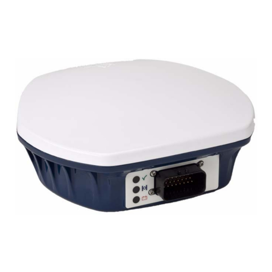
GL1DE • NovAtel ®, RT-20®, RT-2™ and RT-2L For more information about the above, refer to the NovAtel web site at http://www.novatel.com/ support. Once you connect the SMART-MR10 to a vehicle, it begins operating as a fully functional GNSS system. Figure 1 below shows the SMART-MR10 without connecting cables. - Page 19 Introduction Chapter 1 switched to RS422. • Rugged, water and dust tight enclosure, consisting of a cast aluminum base and plastic radome. • Bluetooth • Three (3) daylight viewable status LED indicators. • Range of installation options, including a quick-release mounting plate and a 5m power/data cable with tinned/tagged wires.
-
Page 20: Smart-Mr10 Models
Available models are summarized in Table 1 below. Table 1: SMART-MR10 Controller Models Model Name Firmware Feature SMART-MR10-RT2-G GPS plus GLONASS 1 cm real-time kinematic positions, RT-2 corrections and raw data, code positions and DGPS, OmniSTAR HP/XP/VBS, CDGPS, SBAS, 20 Hz... -
Page 21: Installation And Setup
Chapter 2 Installation and Setup This chapter contains instructions and tips for setting up your SMART-MR10. Additional Equipment Required For the receiver to perform optimally, the following additional equipment is required: • A PC/laptop (user-supplied) • A means of communicating with, and powering, the SMART-MR10 •... -
Page 22: Smart-Mr10 Connector Pin-Out
Chapter 2 Installation and Setup Table 2: SMART-MR10 Connector Pin-Out PWR+ RESERVED PWR- CHASSIS GROUND CAN1- SIGGND1 CAN1+ TXD2 RXD2 TXD1 MODE RTS1/AUXTX RESERVED SIGGND2 RESERVED RESERVED CTS1/AUXRX RESERVED RXD1 RESERVED a. The SMART-MR10 is RS-232/RS-422-selectable through pin 19 MODE, as shown in Table 3. Table 3: Use of MODE Pin MODE Pin Result... -
Page 23: Installing The Pc Utilities
Utilities. These include CDU, a graphical user interface program. Start up the PC/laptop. Insert the accompanying CD in the CD-ROM drive of the computer. You can obtain the latest CDU (and PC utilities) version from the NovAtel Support site at http://www.novatel.com/support/index.htm. SMART-MR10 User Manual Rev 0B... -
Page 24: Power Supply Requirements
If the window does not automatically open when the CD is inserted, select Run from the Start menu and select the Browse button to locate Setup.exe on the CD drive. Install the PC Utilities by advancing through the steps provided in the NovAtel PC Utilities setup program. -
Page 25: Mounting Plates
• Universal mounting plate (NovAtel part number 70023085), shown in Figure 4 on page 25. • Mounting plate with AG GPS 262 layout (NovAtel part number 70023086), shown in Figure 5 on page 26. • Pole-mount (NovAtel part number 70023087), shown in Figure 6 on page 27. -
Page 26: Smart-Mr10 Ag Gps 262 Layout Mounting Plate (70023086)
Chapter 2 Installation and Setup Figure 5: SMART-MR10 AG GPS 262 Layout Mounting Plate (70023086) SMART-MR10 User Manual Rev 0B... -
Page 27: Smart-Mr10 Pole Mount (70023087)
Installation and Setup Chapter 2 INSERT Figure 6: SMART-MR10 Pole Mount (70023087) All measurements are in millimetres unless specified otherwise. SMART-MR10 User Manual Rev 0B... -
Page 28: Mounting The Smart-Mr10
CMOS output; MKI is a 5V-tolerant input. Pin-out information can be found on Page 69. MKI can be used in conjunction with the MARKTIME and MARKPOS logs. For information about these logs, refer to OEMV Family Firmware Reference Manual, available on the NovAtel Support Web site at http://www.novatel.com/support/docupdates.htm. -
Page 29: Smart-Mr10 Led Status Indicators
Installation and Setup Chapter 2 Table 4 shows the meaning of the LED states in the expected sequence after power is applied. Table 4: SMART-MR10 LED Status Indicators Yellow Green Condition Power is not available. (Red indicator may also not be lit if a boot failure has occurred.) Power available but no satellites are being tracked Flashing... -
Page 30: Emulated Radar (Er)
Chapter 2 Installation and Setup distributed in the sky. If it is stuck on blinking yellow, there may be excessive blockage or the unit may be defective. Make sure the unit has an unobstructed view of the sky. Try power cycling the unit. -
Page 31: Available Can Signals On The Smart-Mr10
Installation and Setup Chapter 2 The CAN module is generally not user-interactive. It is activated when a SETCANNAME command is entered, and after a SAVECONFIG, the CAN module is activated immediately on all subsequent start-ups. The module supports the following NMEA2000 Parameter Group Messages (PGN): •... -
Page 32: Operation
Chapter 3 Operation Before operating the SMART-MR10 for the first time, please ensure that you have followed the installation instructions in Chapter 2 Installation and Setup starting on page 21. The following instructions are based on a COM port configuration such as that shown in Figure 8 on page 36. It is assumed that a personal computer (PC), or laptop, is used during initial operation and testing for greater ease and versatility. -
Page 33: Communicating Using A Remote Terminal
Reference Manual for header information. If a persistent error develops, please contact your local NovAtel dealer first. If the problem is still unresolved, please contact NovAtel directly through any of the methods listed in the Customer Service section at the beginning of this manual on page 15. -
Page 34: Communicating With The Receiver Using Cdu
Chapter 3 Operation 3.2.2 Communicating with the Receiver Using CDU Launch the CDU program and select Device | Open from its main menu. The Open Configuration window appears. Figure 7, below, shows an Open Configuration window with three possible configurations already set up. Your configurations may be different or you may have none at all, in which case, the Open Configuration window is empty. -
Page 35: Transmitting And Receiving Corrections
Operation Chapter 3 Commands are typed at the interfacing computing device’s keypad or keyboard, and executed after issuing a carriage return command which is usually the same as pressing the <Enter> key. An example of a response to an input command is the FIX POSITION command, as shown in the following example: [COM2] fix position 51.11635 -114.0383 1048.2 [carriage return] <OK... -
Page 36: Basic Differential Setup
In most cases you need to provide a data link between the base station and rover station (two NovAtel receivers) in order to receive corrections. The application of SBAS corrections to a single receiver are an exception to the base/rover concept. Generally, a link capable of data throughput at a rate of 9600 bits per second, and less than 4.0 s latency, is recommended. -
Page 37: Base Station Configuration
Operation Chapter 3 3.3.1 Base Station Configuration At the base station, enter the following commands: interfacemode port rx_type tx_type [responses] fix position latitude longitude height log port message [trigger [period]] Examples of these commands include the following: RTCA interfacemode com2 none rtca off fix position 51.11358042 -114.04358013 1059.4105 (enter your own lat, lon, hgt) log com2 rtcaobs ontime 1 log com2 rtcaref ontime 10... -
Page 38: Rover Station Configuration
Chapter 3 Operation (for L1/L2 models or cards OEMV1DF, OEMV2G, and OEMV3G) log com2 rtcm1006 ontime 10 log com2 rtcm1033 ontime 10 log com2 rtcm1019 ontime 120 log com2 rtcm1020 ontime 120 CMRPLUS (CMR+) interfacemode com2 none cmr off fix position 51.11358042 -114.04358013 1059.4105 (enter your own lat, lon, hgt) log com2 cmrobs ontime 1 log com2 cmrgloobs ontime 1 log com2 cmrplus ontime 1... -
Page 39: Gps + Glonass Base And Rover Configuration
If you want to mix NovAtel format messages and RTCA, RTCAOBS2, RTCM, RTCMV3, CMR+ or CMR messages on the same port, you can leave the INTERFACEMODE set to NOVATEL and log out variants of the standard correction messages with a NovAtel header. ASCII or binary variants can be requested by simply appending an "A"... -
Page 40: Sbas (Satellite-Based Augmentation Systems)
Operation At the rover station you can leave the INTERFACEMODE default settings (interfacemode com2 novatel novatel). The rover receiver recognizes the default and uses the corrections it receives with a NovAtel header. The PSRDIFFSOURCE and RTKSOURCE commands set the station ID values which identify the base stations from which to accept pseudorange or RTK corrections respectively. - Page 41 EGNOS satellites (via PRNs 120 & 124) should be used with caution. By default NovAtel receivers will not use SBAS signals in test mode. If you wish to use these signals you must issue the following command: sbascontrol enable egnos 0 zerototwo More information on the ESTB can be found at http://www.esa.int/estb.
-
Page 42: Gl1De
“auto” mode, where the filtering parameters are automatically adjusted as vehicle velocity varies between stationary and dynamic states. Refer to the NovAtel white papers at www.novatel.ca/products/whitepapers.htm for more information... -
Page 43: Recommended Configuration
The following commands are recommended to enable pdpfilter enable pdpmode relative auto NovAtel has registered manufactured ID code 305 with J1939. When complete, your configuration can be saved with the SAVECONFIG command. Refer to the OEMV Family Firmware Reference Manual for further details on these commands. -
Page 44: Pc Utilities
The software operates from your PC’s hard drive. You will need to install the software from the CD supplied by NovAtel or from our Web site: Start Microsoft Windows. Place the NovAtel CD in your CD-ROM drive. If the setup utility is not automatically accessible, follow these steps: Select Run from the Start menu. -
Page 45: Cdu
CDU is a 32-bit Windows application. The application provides a graphical user interface (GUI) to allow you to set-up and monitor the operation of the NovAtel receiver by providing a series of windows whose functionality is explained in this section. A help file is included with CDU. To access the file, select Contents from the Help menu. - Page 46 Chapter 4 PC Utilities horizon to directly overhead, respectively. The azimuth is mapped on a compass relative to true North. The colored rings indicate the lowest elevation cut-off angles at which satellites are tracked and can be changed or viewed via the button.
- Page 47 PC Utilities Chapter 4 valid). Normally this represents the latency in the correction data. • The number of satellites used in the solution • The Solution Status • The receiver's date and time (GMT and local) Open this window by selecting Position Window from the View menu or its button in the Window Toolbar.
- Page 48 Chapter 4 PC Utilities subsequent positions, shown with a yellow + marker, are given relative to this initial starting point. The current position is shown with a red + marker. The buttons at the top of the window provide options for controlling the plan display: •...
- Page 49 Refer to the CDU’s online help for more information. • ASCII Messages Window: This window displays ASCII formatted NovAtel logs. To display the ASCII Messages window, select ASCII Messages Window from the View menu or select its button in the Window Toolbar.
-
Page 50: Convert
Chapter 4 PC Utilities Convert Convert is a 32-bit Windows application. It is shown in Figure 9. Convert will accept GPS file formats and convert them to ASCII, Binary or RINEX format. The application also allows the user to screen out particular logs by selecting the desired logs from the list of available logs. This feature is useful for screening particular logs out of large data files in either ASCII or Binary formats. -
Page 51: Novatel Logs For Rinex Conversion
RINEX output files (for example, Company Name, Marker Name and Marker Number). For best results, the NovAtel receiver input data file should contain the logs as in Table 6, NovAtel Logs for RINEX Conversion on page 51. -
Page 52: Convert4 Command Line Switches
Chapter 4 PC Utilities a. Information from this log overrides data entered into the Receiver Number, Type and Version fields using the OBS file button of the RINEX Headers section, see Figure 9 on page 50. 4.3.2 Convert4 Command Line Switches Convert4 supports several command-line switches to facilitate batch processing. -
Page 53: Firmware Upgrades
COM1, and the unit will immediately be ready for operation at a higher level of performance. The first step in upgrading your receiver is to contact your local NovAtel dealer. Your dealer will assist you in selecting the best upgrade option that suits your specific GPS needs. If your needs are still unresolved after seeing your dealer then you can contact NovAtel directly through any of the methods described in the Customer Service section, page 15, at the beginning of this manual. -
Page 54: Updating Using The Winload Utility
NovAtel's FTP site (http://www.novatel.com), or via e-mail (support@novatel.ca). If transferring is not possible, the file can be mailed to you on CD. For more information on how to contact NovAtel Customer Service please see page 15 at the beginning of this manual. -
Page 55: Main Screen Of Winload
PC Utilities Chapter 4 WhatsNew.txt Information on the changes made in the firmware since the last revision XXXX.hex Firmware version upgrade file, where XXXX = program version level (for example, 1001.hex) Using the WinLoad Utility WinLoad is a Windows-based program used to download firmware to OEMV family cards. The main screen is shown in Figure 11 on page 55. -
Page 56: Winload's Open Dialog
Chapter 4 PC Utilities Open a File to Download From the file menu choose Open. Use the Open dialog to browse for your file, see Figure 12, WinLoad’s Open Dialog on page 56. Figure 12: WinLoad’s Open Dialog Once you have selected your file, the name should appear in the main display area and in the title bar, see Figure 13 below. -
Page 57: Com Port Setup
PC Utilities Chapter 4 Figure 14: COM Port Setup Downloading firmware To download firmware follow these steps: Set up the communications port as described in Communications Settings above. Select the file to download, see Open a File to Download on page 56. Make sure the file path and file name are displayed in main display area, see Figure 13, Open File in WinLoad on page 56. -
Page 58: Upgrade Process Complete
Chapter 4 PC Utilities Figure 17: Upgrade Process Complete Close WinLoad. This completes the procedure required to upgrade an OEMV family receiver. SMART-MR10 User Manual Rev 0B... -
Page 59: Bluetooth® Configuration
Chapter 5 Bluetooth® Configuration Bluetooth is a wireless radio communication standard designed for use over short ranges (within 10 m). This chapter describes how to: • Enable Bluetooth on the SMART-MR10 receiver • Set up a PC/laptop with a Bluetooth adaptor •... -
Page 60: Set Up A Pc/Laptop With A Bluetooth Adaptor
Chapter 5 Bluetooth® Configuration Set Up a PC/Laptop with a Bluetooth Adaptor If your PC/laptop is already Bluetooth-equipped and ready, proceed to Section 5.3 on Page 60 With the PC/laptop powered on, install the driver(s) from the disc that came with your Bluetooth adapter. -
Page 61: Communicate With The Smart-Mr10 Using Bluetooth
Bluetooth® Configuration Chapter 5 Figure 22: My Bluetooth Places Window Communicate with the SMART-MR10 Using Bluetooth Double-click the SMART-MR10 device icon in the Entire Bluetooth Neighborhood window, as shown in Figure 22. The PC/laptop searches for available services. If Bluetooth is working properly, a COM port service appears. -
Page 62: Pc/Laptop Com3 Port Assignment
Chapter 5 Bluetooth® Configuration If the code is correct, a new COM dialog opens, showing the PC/laptop COM port that has been assigned to the Bluetooth link. For example, in Figure 24, the PC/laptop port is COM21. Figure 24: PC/Laptop COM3 Port Assignment Open a terminal program (HyperTerminal, for example) and configure it to the serial port specified in the Bluetooth configuration utility. -
Page 63: Stop Communicating With Smart-Mr10 Using Bluetooth
Bluetooth® Configuration Chapter 5 Stop Communicating with SMART-MR10 Using Bluetooth Double-click the Bluetooth icon in the task bar, as shown in Figure 20 on page 60, or select Programs | My Bluetooth Places from the Start menu in Windows. The My Bluetooth Places window opens. -
Page 64: A Technical Specifications
Appendix A Technical Specifications A.1 SMART-MR10 Receiver Performance PERFORMANCE 14 GPS L1, 14 GPS L2, 6 GPS L5 12 GLONASS L1, 12 GLONASS L2 (optional) Channel Configuration 2 SBAS 1 L-band Autonomous (L1) 1.5 m Autonomous (L1/L2) 1.2 m SBAS 0.6 m CDGPS 0.6 m... -
Page 65: Smart-Mr10 Specifications
Appendix A Typical value. Almanac and recent ephemerides saved and approximate time entered. For more information, Please refer to the “SETAPPROXTIME” command in the OEMV Family Firmware Reference Manual found on our Web site at http://www.novatel.com/support/docupdates.htm. A.2 SMART-MR10 Specifications INPUT/OUTPUT CONNECTORS SMART-MR10 COM/ +8 to +36 V DC at 2.5 W (typical while logging) - Page 66 Appendix A Technical Specifications a. When tracking GPS satellites. b. See also the Notice section of this manual starting on Page 13. DIMENSIONS Antenna Phase Centre Notes: 1. All dimensions are in millimetres 2. Mounting holes are labelled according to their size and thread. SMART-MR10 User Manual Rev 0B...
- Page 67 Technical Specifications Appendix A Antenna Phase Centre Note: All dimensions are in millimetres SMART-MR10 User Manual Rev 0B...
- Page 68 Exposed power wires (red for positive and black for negative) are connected to a 12 or 24V vehicular power circuit (or equivalent), which must be protected by a user-supplied 5A fuse (NovAtel recommends an automotive blade-type fuse rated for 5A with an operating voltage of more than 36 V).
-
Page 69: Smart-Mr10 Evaluation Cable Pinouts
Technical Specifications Appendix A Table 7: SMART-MR10 Evaluation Cable Pinouts TYCO COM1 COM2 COM3 TINNED SIGNAL 23-PIN D-SUB D-SUB D-SUB LEAD NAME PWR+ PWR+ PWR- PWR- CAN- CAN- CAN+ CAN+ TXD2 RXD2 TXD1 RTS1/AUXTX/TXD3 SIGGND2 SIGGND2 RESERVED RESERVED RESERVED RESERVED CHASSIS GROUND SIGGND1 SIGGND1... -
Page 70: Smart-Mr10 Streamlined Cable
12 or 24V vehicular power circuit (or equivalent), which must be protected by a user-supplied 5A fuse (NovAtel recommends an automotive blade-type fuse rated for 5A with an operating voltage of more than 36 V). -
Page 71: Smart-Mr10 Streamlined Cable Pinouts
Technical Specifications Appendix A Table 8: SMART-MR10 Streamlined Cable Pinouts TYCO COM1 COM2 TINNED SIGNAL 23-PIN D-SUB D-SUB LEAD NAME PWR+ PWR+ PWR- PWR- RESERVED RESERVED TXD2 RXD2 TXD1 RESERVED SIGGND2 SIGGND2 RESERVED RESERVED RESERVED RESERVED CHASSIS GROUND SIGGND1 SIGGND1 RESERVED RESERVED RESERVED... -
Page 72: Smart-Mr10 Mating Connectors
The connector used in the SMART-MR10 is an “AMPSEAL” dust and water sealed type produced by Tyco. The following part numbers pertain to the mating connector required to make connections to the SMART-MR10. These numbers are provided for information only and are not available from NovAtel as separate parts. -
Page 73: B Commands
Appendix B Commands The SMART-MR10 firmware implements the OEMV family command set, documented in OEMV Family Firmware Reference Manual. For convenience, commonly used SMART-MR10 commands are summarized in Table 11 and documented in this appendix. Table 11: Commonly Used SMART-MR10 Commands in Alphabetical Order ASCII Command Message ID Description... -
Page 74: Btcontrol Enable/Disable Bluetooth
Appendix B Commands Optional parameters are indicated by square brackets ([ ]). For commands that contain optional parameters, the value used if the optional parameter is not specified is given in the syntax table for the command. Data format definitions, as specified in the “Format” field, are detailed in the OEMV Family Firmware Reference Manual. -
Page 75: Com Configure Com Port
Chapter 2 Commands of the OEMV Family Firmware Reference Manual). • Set the interface mode to NovAtel for both input and output (see INTERFACEMODE command in the OEMV Family Firmware Reference Manual). Baud rates higher than 115,200 bps are not supported by standard PC hardware. Special PC hardware may be required for higher rates, including 230400 bps, 460800 bps and 921600 bps. -
Page 76: Com Serial Port Identifiers
Appendix B Commands WARNING!: Use the COM command before using the INTERFACEMODE command on each port. Turn break detection off using the COM command to stop the port from resetting because it is interpreting incoming bits as a break command. Table 12: COM Serial Port Identifiers ASCII Description... -
Page 77: Parity
Commands Appendix B Field ASCII Binary Binary Binary Binary Field Description Type Value Value Format Bytes Offset COM header This field contains the command name or the message header depending on whether the command is abbreviated ASCII, ASCII or binary, respectively. port See Table 12, Port to configure. -
Page 78: Freset Clear Selected Data From Nvm And Reset
Appendix B Commands B.4 FRESET Clear Selected Data from NVM and Reset This command is extended to include SMART-MR10 features. An additional target field, userdata (value = 10), resets only the SMART-MR10 user data NVM, thereby resetting all parameters indicated in this document as “Stored in NVM”... -
Page 79: Log Request Logs From The Receiver
Commands Appendix B B.5 LOG Request Logs from the Receiver Many different types of data can be logged using several different methods of triggering the log events. Every log element can be directed to any combination of the three COM ports and three USB ports. - Page 80 Appendix B Commands Abbreviated ASCII Syntax: Message ID: 1 LOG [port] message [trigger [period [offset [hold]]]] Factory Default: log com1 rxstatuseventa onnew 0 0 hold log com2 rxstatuseventa onnew 0 0 hold log com3 rxstatuseventa onnew 0 0 hold log aux rxstatuseventa onnew 0 0 hold log usb1 rxstatuseventa onnew 0 0 hold log usb2 rxstatuseventa onnew 0 0 hold log usb3 rxstatuseventa onnew 0 0 hold...
- Page 81 Commands Appendix B Field ASCII Field Field Description Type Name Value This field contains the command name or (ASCII) the message header depending on whether header the command is abbreviated ASCII or ASCII respectively. port See Table 16, Output port Enum Detailed Serial Port (default = THISPORT)
-
Page 82: Detailed Serial Port Identifiers
Appendix B Commands Table 16: Detailed Serial Port Identifiers Decimal Port ASCII Port Hex Port Description Name Value Value NO_PORTS No ports specified COM1_ALL All virtual ports for COM port 1 COM2_ALL All virtual ports for COM port 2 COM3_ALL All virtual ports for COM port 3 THISPORT_ALL All virtual ports for the current port... - Page 83 Commands Appendix B Decimal Port ASCII Port Hex Port Description Name Value Value THISPORT_31 Current COM port, virtual port 31 FILE User-specified file destination, 0 FILE_1 User-specified file destination, 1 FILE_31 User-specified file destination, 31 XCOM1 Virtual COM1 port, virtual port 0 XCOM1_1 Virtual COM1 port, virtual port 1 XCOM1_31...
-
Page 84: Pdpfilter Enable, Disable Or Reset The Pdp Filter
Enum A reset clears the filter memory so ENABLE that the pdp filter can start over. RESET Refer also to our application note on Pseudorange/Delta-Phase (PDP), available on our Web site as APN-038 at http://www.novatel.com/support/applicationnotes.htm SMART-MR10 User Manual Rev 0B... -
Page 85: Pdpmode Select The Pdp Mode And Dynamics
Commands Appendix B B.7 PDPMODE Select the PDP mode and dynamics This command allows you to select the mode and dynamics of the PDP filter. You must issue a PDPFILTER enable command before the PDPMODE command. See PDPFILTER Enable, disable or reset the PDP filter starting on page 84. GL1DE If you choose RELATIVE mode ( ) while in WAAS or CDGPS mode:... -
Page 86: Radarcfg Configure The Er Output
Appendix B Commands B.8 RADARCFG Configure the ER output Use this command to configure the Emulated Radar (ER) output. ER is available through the SMART- MR10 multi-cable, see page 69 for pin-out details. Syntax radarcfg switch freq_step update_rate resp_mode threshold Message ID = 8192 Field Data... -
Page 87: Response Modes
Commands Appendix B Table 17: Response Modes Mode Description 2000 2000 ms The time period over which to smooth 1000 1000 ms velocity samples 500 ms (default) Automatically switches between 1000 and 500 ms Performs no smoothing Example 1 to disable radar emulation: radarcfg disable 26.11 1 1 2 Example 2 to set the frequency step to 36.11 Hz/kph, update rate to 1 Hz and no smoothing:... -
Page 88: Reset Performs A Hardware Reset
Appendix B Commands B.9 RESET Performs a hardware reset This command performs a hardware reset. Following a RESET command, the receiver initiates a cold- start boot up. Therefore, the receiver configuration reverts either to the factory default, if no user configuration was saved, or the last SAVECONFIG settings. -
Page 89: Sbascontrol Set Sbas Test Mode And Prn
Commands Appendix B B.10 SBASCONTROL Set SBAS test mode and PRN This command allows you to dictate how the receiver handles Satellite Based Augmentation System (SBAS) corrections. The receiver automatically switches to Pseudorange Differential (RTCM or RTCA) or RTK if the appropriate corrections are received, regardless of the current setting. To enable the position solution corrections, you must issue the SBASCONTROL ENABLE command. - Page 90 Appendix B Commands Factory Default: sbascontrol disable auto 0 none Abbreviated ASCII Example 1: sbascontrol enable waas 0 zerototwo NovAtel's OEMV receivers work with SBAS systems including EGNOS (Europe), MSAS (Japan) and WAAS (North America) System Types ASCII Binary Description NONE Don’t use any SBAS satellites...
-
Page 91: C Logs
Appendix C Logs C.1 Position Logs C.1.1 NMEA Logs The NMEA logs (receiver outputs) supported by the SMART-MR10 are summarized in Chapter 3 of the OEMV Family Firmware Reference Manual in section "NMEA Standard Logs". The available logs include: • GPGGA, which outputs a log of position system fix data and undulation. - Page 92 Configure the remaining fields then click Add. C.1.2 NovAtel Position Logs In addition to NMEA logs, NovAtel supports a range of non-NMEA position logs, described in the OEMV Family Firmware Reference Manual, including: • BESTPOS: This log contains the best available position (GPS and GLONASS if available), computed by the receiver, for example: log bestposa ontime 0.5...
-
Page 93: Other Logs
The SMART-MR10 firmware generates the logs in Table 18, in addition to those of the OEMV Family log set. Refer to the OEMV Family Firmware Reference Manual, which also contains procedures and explanations related to data logging and is available from our Web site at: http://www.novatel.com/support/docupdates.htm Table 18: SMART-MR10 Logs in Alphabetical Order Message ID... - Page 94 Appendix C Logs Binary Binary Field # Field type Data Description Format Bytes Offset RADAR- Log header SIGNAL header sol status Solution status, see Table 20, Solution Status on Enum Page 96 vel type Velocity type, see Table 19, Position or Velocity Enum Type on Page 95 speed...
-
Page 95: Position Or Velocity Type
Logs Appendix C Table 19: Position or Velocity Type Type (binary) Type (ASCII) Description NONE No solution FIXEDPOS Position has been fixed by the FIX POSITION command FIXEDHEIGHT Position has been fixed by the FIX HEIGHT/AUTO command DOPPLER_VELOCITY Velocity computed using instantaneous Doppler SINGLE Single point position PSRDIFF... -
Page 96: Solution Status
Appendix C Logs Table 20: Solution Status Solution Status Description (Binary) (ASCII) SOL_COMPUTED Solution computed INSUFFICIENT_OBS Insufficient observations NO_CONVERGENCE No convergence SINGULARITY Singularity at parameters matrix COV_TRACE Covariance trace exceeds maximum (trace > 1000 m) TEST_DIST Test distance exceeded (maximum of 3 rejections if distance >... -
Page 97: Component Type
Logs Appendix C C.2.2 VERSION HW & SW Versions and Serial Numbers The Component Type of the VERSION log, refer to the OEMV Family Firmware Reference Manual, is extended to include SMART-MR10 information as in Table . Table 21: Component Type ASCII Value Description Binary Value... -
Page 98: D Replacement Parts
Appendix D Replacement Parts The following are a list of the replacement parts available for your NovAtel SMART-MR10 receiver. Should you require assistance, or need to order additional components, please contact your local NovAtel dealer or Customer Service representative. D.1 SMART-MR10... - Page 99 Index cold start accuracy COM command position COM port velocity command ALIGN almanac communication antenna error message internal example specifications in CDU ascii interface AUTH command multiple authorization note AUX port port identifier pre-configure prompt communication base station bidirectional baseline Bluetooth baud rate baud rate, see bps...
- Page 100 Index specifications EGNOS Controller Area Network EGNOS (European SBAS) Convert software e-mail copyright Emulated Radar (ER) operation requirements enable Bluetooth customer interface cable ESTB Customer Service factory default data reset Bluetooth setting collect features – erase filter – format firmware upgrades L-band FRESET command link...
- Page 101 (PDP) MSAS (Japanese SBAS) RADARCFG command NMEA logs RADARSIGNAL log note, logging receiver outputs Notices receiver status NovAtel Inc. relative pseudorange/delta phase NovAtel position logs replacement parts reset FRESET command hardware operation option optionality target outages revision, firmware output...
- Page 102 Index rover station WAAS (Wide Area Augmentation Sys- configuration tem) RTCA Warning RTCM RTCM1819 RTCMV3 voltage warranty antenna Web site satellite – windows in CDU coverage WinLoad SBAS control system type self-test serial cable number port sleep Bluetooth SMART-MR10 models smooth standby mode, PC static mode...
- Page 103 Index SMART-MR10 User Manual Rev 0B...
- Page 104 OM-20000130 Rev 0B 2010/05/12...
Need help?
Do you have a question about the SMART-MR10-RT2 and is the answer not in the manual?
Questions and answers