Table of Contents
Advertisement
Quick Links
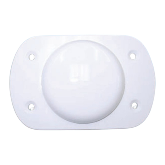
The 42G1215A-XT-1 is an active antenna designed to operate at the GPS L1 and L2 frequencies, 1575.42
and 1227.60 MHz. The antenna is aircraft certified for navigation. This guide provides the information
needed to install and use the antenna.
ADDITIONAL EQUIPMENT REQUIRED
• A device with an antenna input port that both receives the RF signal and provides 2.5 to 24.0 VDC to the
antenna is required to set up the 42G1215A-XT-1. (NovAtel GPS receivers provide the necessary power
through their antenna RF connectors.)
• Coaxial cable with a male TNC connector
INSTALLING THE ANTENNA
Both the input DC power and the output RF signal flow over a single coaxial cable connected to the unit's
TNC female connector.
The antenna is attached to a surface by means of an ARINC-743 Bolt Pattern. Four screws pass through
the housing of the antenna.
Install the antenna as follows:
1. Place the o-ring into groove on the antenna base (o-ring supplied).
User-supplied o-ring grease can be used to hold the o-ring in the groove
during installation.
2. Pre-drill the mounting holes and the connector hole on the surface. Refer to the Mechanical Drawings
section of this guide for details on the ARINC-743 mounting pattern.
42G1215A-XT-1
ANTENNA GUIDE
OM-20000152
Rev 1
December 2013
1
Advertisement
Table of Contents

Related Manuals for Novatel 42G1215A-XT-1


Summary of Contents for Novatel 42G1215A-XT-1
- Page 1 Rev 1 December 2013 The 42G1215A-XT-1 is an active antenna designed to operate at the GPS L1 and L2 frequencies, 1575.42 and 1227.60 MHz. The antenna is aircraft certified for navigation. This guide provides the information needed to install and use the antenna.
- Page 2 6. Attach the other end of the coaxial cable to the antenna input port of the receiving device. The receiv- ing device must be able to provide power as detailed in the SPECIFICATIONS section of this guide. All NovAtel GPS receivers provide the necessary power through their antenna RF connectors.
- Page 3 The graphic above shows examples of where the 42G1215A-XT-1 antenna may be located on an aircraft or vehicle (not to scale). ANTENNA CARE The 42G1215A-XT-1 is designed to withstand the elements, including rain, snow and dust. However, to ensure your antenna performs optimally, keep the radome clean and brush off any ice and snow. In addi- tion, ensure the TNC connector remains clean and dry and replace the dust cap when a cable is not connected.
- Page 4 L1 ELEVATION GAIN PATTERN Max = 4.71 dB L2 ELEVATION GAIN PATTERN Max = 3.36 dB...
- Page 5 SPECIFICATIONS L1:1575.42 ±12 MHz 3 dB pass band (typical) L2:1227.60 ±12 MHz Out-of-band rejection > 40 dBc (±50 MHz) (typical) L1:+4.7 dBicL2:+3.3 dBic Gain at zenith ( = 90°) Gain roll-off (zenith to L1:+6.5 dBL2:+7.1 dB LNA gain (typical) L1: 31dB / L2: 33 dB ±2 dB Polarization Right-hand circular...
- Page 6 MECHANICAL DRAWINGS Dimensions are in inches followed by [mm] HEIGHT...
- Page 7 Please check our website for updates to this manual at www.novatel.com/Downloads/docupdates.html the websites mentioned above. If you need any further advice on this matter, please visit our website at www.novatel.com. Other methods of contacting Customer Service can be found on the last panel of this guide.
- Page 8 (ii) defects, errors or nonconformities in the products due to modifications, alterations, additions or changes not made in accordance with NovAtel’s specifications or authorized by NovAtel, (iii) normal wear and tear, (iv) damage cause by force of nature or act of any third person, (v) ship- ping damage;...
Need help?
Do you have a question about the 42G1215A-XT-1 and is the answer not in the manual?
Questions and answers