Table of Contents
Advertisement
Quick Links
Download this manual
See also:
User Manual
Advertisement
Table of Contents

Related Manuals for molex Brad HarshIO 600 eIP


Summary of Contents for molex Brad HarshIO 600 eIP
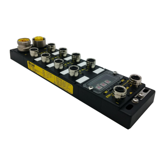
- Page 1 User’s Manual HarshIO 600 eIP IP67 IO-Link Modules for EtherNet/IP Brad™ from Molex Version 1.2 July 31 , 2018 • i • HarshIO 600 eIP IP67 IO-Link Modules for EtherNet/IP...
- Page 2 Although every effort has been made to ensure the accuracy of this document, all information is subject to change without notice. Molex takes no liability for any errors in this document or for direct, indirect, or consequential damage resulting from the use of this manual.
- Page 3 STATEMENT OF LIMITED WARRANTY Brad™ from Molex, manufacturer of HarshIO products, warrants to Buyer that products, except software, manufactured by Brad™ will be free from defects in material and workmanship. Brad™ obligation under this warranty will be limited to replacing the defective parts within one year of the date of purchasing. Products may be returned by Buyer only after permission has been obtained from Brad™.
-
Page 4: Table Of Contents
Table of contents General Safety Instructions ..............6 General information ....................6 Personnel qualifications ..................6 Preventive messages ....................6 Usage compliance ....................6 Device installation and set-up ................. 7 Device operation ..................... 8 Electrical, mechanical and thermal specifications ........... 8 Preventive and corrective maintenance .............. - Page 5 ID Validation & Data Storage Modes – Identical/Compatible with Restore ..52 ID Validation & Data Storage Modes – Identical/Compatible with Backup & Restore ..........................53 EtherNet/IP Object Classes ............... 55 Identity (0x01) ......................55 Message Router (0x02) ..................57 Assembly (0x04) ....................
-
Page 6: General Safety Instructions
1. General Safety Instructions General information The current documentation is intended for persons technically qualified to install, use and service the products described herein. It contains the necessary information for proper use of the products. However, for advanced use of our products, please contact your nearest dealer for additional information. The content of this documentation is not binding and cannot extend or limit warranties. -
Page 7: Device Installation And Set-Up
As a general rule, if all the handling, transportation, and storage recommendations and installation, operation and maintenance instructions are followed, the products will operate correctly without risk for personnel or hardware. Device installation and set-up It is important to follow the rules below when installing and setting up the Brad™ HarshIO. If system installation includes products more than thirty meters away from each other, the basic cabling rules must be closely followed. -
Page 8: Device Operation
Device operation Because Brad™ HarshIO devices are components of a control system, the safety of the entire automated system, including that of the installation and the application, cannot be dealt with in this document. For further information, see IEC 61131-4, describing risk reduction measures for PLC users. See the documentation of the specific products involved for more information on operation safety. -
Page 9: General Description
All Brad™ HarshIO modules, with Micro-Change ® (M12) ports, accept both standard threaded cordsets and the Molex Ultra-Lock™ system. Ultra-Lock™ connection System! The fastest, easiest and most secure connection ever designed. Ultra-Lock™ technology is designed for higher performance and reliability. Discover how the... -
Page 10: Overview
Overview The HarshIO module is consisted of three main parts. • 10 • HarshIO 600 eIP IP67 IO-Link Modules for EtherNet/IP... - Page 11 Power distribution HarshIO EtherNet/IP IO-Link Master modules can be powered up through 4-pole or 5-pole Mini-Change (7/8”) power supply connectors identified by 2 different part numbers. This specificity allows complying with regional power requirements. The HarshIO module integrates 2 power connectors 1x Male and 1x Female for daisy chain installation simplifying the power distribution across the application.
- Page 12 Daisy-chain topology The daisy-chain topology allows you to connect I/O modules or additional equipment in one line, from one device to the next in an optimized way along the production line. When considering the daisy chain topology, note that • If a module, somewhere in the middle of the chain, has the network cable disconnected or power to the module is removed then communications to any module located down the chain will be lost.
- Page 13 Combination of various topologies Combining star and daisy-chain topologies allows you to connect HarshIO modules with mixed HarshIO modules or additional network devices. Ethernet Switch • 13 • HarshIO 600 eIP IP67 IO-Link Modules for EtherNet/IP...
- Page 14 Signal The HarshIO module supports up to 8 I/O ports with each: • 1x Channel with IO-Link Master communication on Pin 4 • 1x Channel with user configurable digital I/O on Pin 2 The IO-Link Master communication channels can behave as a standard digital Input or Output or connect any IO-Link devices such as: •...
-
Page 15: Technical Data
3. Technical Data Dimensions (mm) • 15 • HarshIO 600 eIP IP67 IO-Link Modules for EtherNet/IP... -
Page 16: Electrical Power Data
Electrical Power Data Module 4-pin power version 5-pin power version Product Reference TCIEI-888P-DYU TCIEI-888P-D1U Power Mini Change (7/8”), 4-pin, male, Maximum 8 A Mini Change (7/8”), 5-pin, male, Maximum 8 A Power IN connector Mini Change (7/8”), 4-pin, female, Maximum 8 A Mini Change (7/8”), 5-pin, female, Maximum 8 A Power OUT connector 24 VDC, -20%/+25% (19.2 VDC / 30 VDC) protected against power crossing) - Page 17 Note! The I/O port can supply power from the following pin: • Pin1 1.6 A • Pin 2 2 A • Pin 4 500 mA All current supplied will be returning through Pin3 (L-). Make sure that the total current on Pin3 does not exceed 4 A (M12 standard max current support).
-
Page 18: Ethernet/Ip
EtherNet/IP EtherNet/IP Fieldbus Ethernet connectors 2 x M12, 4-pin, female, D-Coded, shielded IP setting DHCP (based on MAC & on Client_ID), Static IP, Stored IP EtherNet/IP Adapter according specification Vol 1-3.17 (CIP) and Vol 2 – 1.18 (EtherNet/IP) Protocol Data access Implicit messages for I/O data transfer •... -
Page 19: Mechanical And Environmental Data
Mechanical and Environmental Data Mechanical 235 x 60 x 39 mm (9.25" x 2.36” x 1.53") Housing dimensions Housing material PBT VALOX 420 SEO Black 7701 Flammability Standard UL 94 V-0 Corner mounting holes 4 mounting holes, 5 x10 mm Ground stud Yes (allows the continuity of the ground when the module is mounted on the chassis machine) Operating temperature... -
Page 20: System Description
4. System Description Physical description Mounting screw (Functional Earth #0 – FE0) Shield Plate Power OUT (Uo) Power IN (Ui) I/O Connectors Port 0 Port 4 Port 1 Port 5 Plastic label Port 2 Port 6 Port 3 Port 7 3x Rotary switches Ethernet Port (ETH1) Ethernet Port (ETH2) -
Page 21: Power Connectors
Power connectors Pinout and orientation TCIEP-888P-D1U 5 pins Power Connector - Description FE (Functional Earth) 24 VDC (UL - Outputs power supply) 24 VDC (UB - Module & Inputs power supply) LEDs UL indicator UB indicator TCIEP-888P-DYU 4 pins Power Connector - Description 24 VDC (UL - Outputs power supply) 24 VDC (UB - Module &... - Page 22 UB & UL support a power interruption according to EN 60204-1. Note! If you only use digital input devices, there is no need to supply power on UL. UL is only required for Outputs on Pin2 or Extended power supply for Molex IO-Link I/O Hubs. • 22 •...
- Page 23 Protection strategies on electrical faults Multiple electrical faults may occur (intentionally or not) which are: - Overload / Overcurrent - Short Circuit - Under voltage - Over voltage According to the type, protection strategies are applied for Pin 1, Pin 2 and Pin 4 according to the IO configuration and on all the ports or on a single one depending on the type of issue.
- Page 24 LEDs and status bits The table below shows the LEDs state according to power supply voltages applied and the corresponding status bits. LEDs Color State Input Process data - State & Power supply voltages Status bit Voltage not present (UL=0 V) No error If no DO configured Powered and UB not powered...
-
Page 25: Ethernet Connectors And Encoding Switches
Ethernet connectors and encoding switches Pinout and orientation Description Note! Shell of each connector (FE1 & FE2) is connected to its own FE screw tab. Note! M12 Ethernet connector shall be screwed with a torque of 2.0 Nm to ensure a correct sealing to achieve IP67 rating. - Page 26 Networks LEDs The left side bi-color red/green LED is network status indicator (NET) and the right side bi-color red/green LED is internal module status indicator (MOD). MOD indicator NET indicator Color State Meaning No UB power supply or no IP address assigned IP address assigned &...
- Page 27 Use of the rotaries 3 decimal rotary switches are located under the window and oriented as shown below. “x100 x10 x1” labels are printed below of the rotary (PCB silkscreen). x100 Note! The module window shall be screwed with a torque of 0.3 Nm to ensure a correct sealing to achieve IP67 rating and shall be closed during working operation.
- Page 28 HarshIO module gets its IP address, IP mask address and DHCP gateway address according DHCP method based on MAC Mode address. It will send the DHCP request indefinitely until (based on MAC receiving an IP address) HarshIO module gets its IP address, IP mask address and gateway address according DHCP method based on Client DHCP ID=”BRAD_xy”.
-
Page 29: I/O Connectors
Warning! If you change the rotary position while the EtherNet/IP scanner has an I/O connection established, the connection will be closed and the Fail Safe Mode will be applied. A reset command or a power cycle will be required. I/O connectors Pinout and orientation I/O Connector - Description Powered by... - Page 30 Note! M12 accessories (cordsets, plugs …) connected to the module I/O and network connectors shall be screwed with a torque of 2.0 Nm to ensure a correct sealing to achieve IP67 rating. Note! At the module power up and before the first connection with the PLC, Pin #2 & Pin #4 are configured as Digital Input.
- Page 31 Blinking The BLUE led shows the actual IO-Link state: blue IOLSx =3 & IOLDx=1 Blinking at 1 Hz: searching device, wakeup mode IOLSx =0 & IOLDx=1 Blinking at 2 Hz: device found and in state PREOPERATE SO: energized and shorted to ground CSx=1 SO: when overload detected (>500mA) UVUB =1...
-
Page 32: Functional Earth Connections
Functional earth connections The functional earth (FE0) shall always be connected to ground to ensure proper operation of the module. The two functional earth (FE1 & FE2) are not connected to the functional earth (FE0). Functional Earth N°0 (FE0) Functional Earth N°1 (FE1) Functional Earth N°2 (FE2) Note! 3 screw terminals functional earth connections (FE0 / FE1 / FE2) are galvanically... - Page 33 According to its position, the shield plate offers different functional earth connection to ground. Switch Switch • 33 • HarshIO 600 eIP IP67 IO-Link Modules for EtherNet/IP...
-
Page 34: I/O Data Mapping
5. I/O Data mapping I/O messaging HarshIO module supports up to a maximum of 8 I/O connections. Fewer connections allow faster data I/O update rates (RPI value). I/O Connections: HarshIO module supports 2 transport Class 1 I/O connections (Cyclic and Change-Of-State triggers): 1x Exclusive Owner ▪... -
Page 35: Ethernet/Ip Assembly Instances
EtherNet/IP Assembly instances The I/O process data are available through the EtherNet/IP assembly instances. Below the list according to the connection type. Input Output Configuration Data length Data length Data length EDS entry Assembly (bytes) Assembly (bytes) Assembly (bytes) Exclusive Owner Digital I/O &... -
Page 36: Input Process Data Mapping
Input process data mapping Assembly #110 - Digital data + with no IO-Link data Process Input Data (8 bytes) Offset (in byte) DI15 SI14 DI13 SI12 DI11 SI10 OLUL OVUL UVUL OLUB OVUB UVUB CS15 CS14 CS13 CS12 CS11 CS10 IOML6 IOLM4 IOLM2... - Page 37 Assembly #111 - Digital data + with 4 bytes data per IO-Link device Input Process Data (8 bytes) Offset (in byte) DI15 SI14 DI13 SI12 DI11 SI10 OLUL OVUL UVUL OLUB OVUB UVUB CS15 CS14 CS13 CS12 CS11 CS10 IOLM6 IOLM4 IOLM2 IOLM0...
- Page 38 Assembly #112 - Digital data + with 8 bytes data per IO-Link device Input Process Data (8 bytes) Offset (in byte) DI15 SI14 DI13 SI12 DI11 SI10 OLUL OVUL UVUL OLUB OVUB UVUB CS15 CS14 CS13 CS12 CS11 CS10 IOLM6 IOLM4 IOLM2 IOLM0...
-
Page 39: Output Process Data Mapping
Output process data mapping Assembly #121 - Digital data + with 4 bytes data per IO-Link device Output Process Data (4 bytes) Offset (in byte) DO15 SO14 DO13 SO12 DO11 SO10 CSIC14 CSIC12 CSIC10 CSIC8 CSIC6 CSIC4 CSIC2 CSIC0 Offset (in byte) per IO-Link channel IO-Link Process Data (4 bytes) IO-Link Output Process Data (4bytes) SOx: SO - Standard Output data (x = Channel number) –... -
Page 40: Configuration Data Mapping
For Output and IO-Link Process Data information, refer to output assembly #121 assembly #122 Warning! If the IO-Link Output Process Data size configured (ex: 4 bytes) is lower than the IO- Link Output Process Data size of the connected IO-Link device (ex: 32 bytes), the EtherNet/IP connection will be established and the first 4 output bytes of data will be produced. - Page 41 3 = IO-Link Note! “Power Supply” on Pin2 is a 24 voltage applied continuously after the EtherNet/IP connection. It allows to power up the Molex IO-Link hub TEDIO-8D0P-808 and TEDIO- 8B4P-808. DO / SO Fail-Safe Mode This parameter is used for setting the fail-safe value behavior of Digital Output (DO) configured on Pin#2 and of Standard Digital Output (SO) configured on Pin4.
- Page 42 DPP2 Data is an area of 16 Bytes that will be sent in case of DDP2 Enable set from the IO-Link Master to the IO-Link device at each connection. Note! For ease of programming in Studio 5000, Molex provides an AOI (Add-On-Instruction) to use pre-named tags instead of using Generic tags. Please refer to chapter Rockwell Studio 5000.
-
Page 43: Io-Link Features & Behaviors
If the Vendor ID is set, the Device ID must be set as well because both are always checked together (and vice and versa). Example: The vendor ID of Molex IO-Link Hub 16 inputs (TEDIO-8DOP-808) is a 16-bits value (2 bytes) and the Device ID is a 24-bits value (3 bytes) Vendor ID: 0x0127... -
Page 44: Data Storage (Ds)
Bytes Data (Hex) Bytes Data (Hex) 24 (MSB) 01 (MSB) 27 (LSB) Serial Number (S/N) For each IO-Link port, S/N is stored in non-volatile memory into the master and is used for the validation process (identical only). Out of the box, the S/N of the IO-Link Port is empty. At first connection, the S/N of the connected IO-Link Device will be stored and used for ID validation (Identical mode only) each time it is required. - Page 45 a. Data Storage initialization Out of the Box, the HarshIO module is empty with no IO-Link Device DS File. Several methods can be used to upload a DS File into one IO-Link Master Port: Automatic: At first connection with an IO-Link Device, the module will upload (backup) the parameters of the IO-Link device (regardless of the configured Data Storage mode).
-
Page 46: Si With Io-Link
Data Storage “Backup and Restore”: In this mode, the synchronization of the IO-Link device parameters is bidirectional between the IOLM and IOLD. This mode allows to do a backup of the IO-Link device parameters from the IO-Link device to the IO- Link Master or to do a restore of the IO-Link device parameters from the IO-Link Master to the IO-Link device. -
Page 47: Io-Link Events And Errors Codes
In SI mode, you can switch back to IO-Link mode by using the switching (with the CSICx bit=1), In such case, the IO-Link communication starts in operate mode. It means that: The process data are in valid state and accessible for the user. All the other IO-Link feature can be performed (Diagnostic, parametrization…) Warning! The IO-Link device shall support the SI with IO-Link mode. -
Page 48: Io-Link Isdu Access
Rockwell PLC ladder code (TCIEI_AOI & Sample_Ladder_Code.ACD) is available from this link. Please also refer to the chapter IO-Link parameter object You can also use the Molex EIP Tool (Ethernet/IP Tool) available from this link. IO-Link device diagnostic The IO-Link device diagnostic can be accessible from:... -
Page 49: Io-Link Device Replacement
IO-Link Device replacement ID Validation & Data Storage Modes – None (no ID checking) Molex IO-Link hub TEDIO-8B4P-808 Vendor ID: 0x127 Device ID: 0x252980 S/N: 5678 IO-Link communication OK ID Validation – None Molex IO-Link hub TEDIO-8D0P-808 Vendor ID: 0x127... -
Page 50: Id Validation & Data Storage Modes - Compatible
ID Validation & Data Storage Modes Compatible – Molex IO-Link hub TEDIO-8B4P-808 Vendor ID: 0x127 Device ID: 0x252980 S/N: 5678 IO-Link communication ID Validation – Compatible Vendor ID: 0x127 Device ID: 0x252980 Molex IO-Link hub TEDIO-8D0P-808 Vendor ID: 0x127 Device ID: 0x243000... -
Page 51: Id Validation & Data Storage Modes - Identical
ID Validation & Data Storage Modes – Identical Molex IO-Link hub TEDIO-8B4P-808 Vendor ID: 0x127 Device ID: 0x252980 S/N: 5678 IO-Link communication ID Validation – Identical Vendor ID: 0x127 Device ID: 0x252980 Molex IO-Link hub TEDIO-8B4P-808 Vendor ID: 0x127 Device ID: 0x252980... -
Page 52: Id Validation & Data Storage Modes - Identical/Compatible With Restore
ID Validation – identical/Compatible with Restore. The Molex IO-Link hub (Param ABC) is swapped by a Molex IO-Link hub (Param DEF). If the ID validation is successful, the HarshIO module will restore param ABC. Therefore, the param DEF will be overwritten by the param ABC. -
Page 53: Id Validation & Data Storage Modes - Identical/Compatible With Backup & Restore
Backup and Restore. The Molex IO-Link hub (Param ABC) is swapped by a Molex IO-Link hub (Param DEF). If the ID validation is successful, the HarshIO module will restore param ABC. Therefore, the param DEF will be overwritten by the param ABC. - Page 54 ABC. In such case, and to align param, the user will force a restore (Force restore ISDU request) if param ABC must be downloaded to the Molex IO-Link hub or force a backup (Force backup ISDU request) if param GHI must be uploaded and stored into the DS file.
-
Page 55: Ethernet/Ip Object Classes
8. EtherNet/IP Object Classes The following services are accessible by using EtherNet/IP Explicit Messaging. Identity (0x01) This object allows reading the identity of the module. Class Attributes Description Limits Revision Max Instance Number of instances ... - Page 56 Description Values Owned Set to 1 when at least one EO connection is present Configured Set to 1 Minor Recoverable fault Set when UB detect an under voltage Major Recoverable fault Set when Rotary position changes Set when Configuration Control changes (attr3, 0xF5) Set when Interface Configuration changes (attr5, 0xF5) Set when IP address is lost.
-
Page 57: Message Router (0X02)
Message Router (0x02) Class Attributes Description Limits Revision Optional Attribute List Optional Service List Max ID of class attributes Max ID of instance attributes Supported Not Supported Class Services Service Param. -
Page 58: Assembly (0X04)
Assembly (0x04) This object allows to access I/O process data. Class Attributes Description Limits Revision Max Instance Number of instances Supported Not supported Class Services Service Param. Options Get_Attribute_Single Instance Attributes Description Limits ... -
Page 59: Connection Manager (0X06)
Connection Manager (0x06) Class Attributes Description Limits Revision Max Instance Number of instances Supported Not supported Class Services Service Param. Options Get_Attributes_All Get_Attribute_Single Instance Attributes Description Limits Open Requests ... -
Page 60: Tcp/Ip Interface (0Xf5)
TCP/IP Interface (0xF5) Class Attributes Description Limits Revision Max Instance Number of instances Supported Not supported Class Services Service Param. Options Get_Attributes_All Get_Attribute_Single Instance Attributes Description Values NRAM Rotary DHCP Static DHCP Static ... -
Page 61: Ethernet Link (0Xf6)
Ethernet Link (0xF6) Class Attributes Description Limits Revision Max Instance Number of Instance Supported Not supported Class Services Service Param. Options Get_Attributes_All Get_Attribute_Single Instance Attributes Description Values Instance 1 Instance 2 Instance 3 (ETH 1) (ETH 2) Internal Port... -
Page 62: File (0X37)
File (0x37) Class Attributes Description Limits Revision Max Instance Number of Instance Directory Supported Not supported Class Services Service Param. Options Get_Attribute_Single Instance Attributes 101…108 Description 200 (EDS File) (DS File #1…#8) ... -
Page 63: Dlr (0X47)
DLR (0x47) Class Attributes Description Limits Revision Max Instance Supported Not supported Class Services Service Param. Options Get_Attribute_Single Instance Attributes Description Limits Network Topology Network Status Ring Supervisor Status ... -
Page 64: Qos (0X48)
QoS (0x48) Class Attributes Description Limits Revision Max Instance Number of Instance Supported Not supported Class Services Service Param. Options Get_Attribute_Single Instance Attributes Description Limits DSCP Urgent DSCP value for CIP transport class 0/1 Urgent priority messages. -
Page 65: Io-Link (0X310)
IO-Link (0x310) Class Attributes Description of Attr ID Access Rule NV-RAM Name Data Type Semantics of Value Attribute Revision UINT Revision of the Object Max Instance UINT Maximum number of instance of this object Number of instances UINT Number of object instances currently created at this class level of the device. - Page 66 Instance Attributes Attr Access Description of Name Data Type Semantics of Value Rule Attribute IO-Link Status UINT See input assembly as well Validation status / Port Existing or not Data Storage Status IO-Link STRUCT OF Configuration UINT Mode 0: None 1: Compatible 2: Compatible with Backup and Restore 3: Compatible with Restore...
- Page 67 Instance Services Service Service Name Description of Service Code Get_Attribut_All 0x01 Get Attribut Single 0x0E Set Attribut Single 0x10 Learn serial Number Only works when module is in validation identical. The current saved SN is clear 0x4B and the one of the connected IO-Link device is learnt and saved in memory This command shall be sent when no IO-Link device is connected.
- Page 68 Please refer to the specific IO-Link device user’s manual IO-Link device additional error USINT Example: user’s Reading the L+ voltage of the Molex HarshIO IO-Link digital hubs (Refer to the TEDIO-8D0P-808 manual) connected to Port 0 Parameters Description 0x310 Class...
- Page 69 No data are set into the response. Negative Response: Refer to the above chapter Service Read ISDU details Example: Changing the current input filter delay 1ms to 3ms of the Molex HarshIO IO-Link digital hubs (Refer to the user’s manual) connected to Port 0.
-
Page 70: Getting Started
9. Getting started Packaging content Each product packaging includes: • 1x HarshIO 600 EtherNet/IP IO-Link Master module • 9 x plastic labels (for digital channel labeling) • 4 x M12 male closure caps (for sealing unused ports) • Flyer Out of box settings IP address: DHCP Subnet mask:... -
Page 71: Rockwell Studio 5000
4. Apply Power Switch on the power supply module and observe the LEDs status indicator. If the module is correctly wired, then the following LEDs status indicator should be: Color State Module state Fixed green Actuator voltage present Fixed green Logic/Communications/sensor voltage present (Pin 2) DI is not set / D0 is not energized... -
Page 72: Firmware Update
If you need to update the HarshIO module, please go on the support web page and fill the Support Request Form. See Product Support section below. Molex specialists will advise and provide you with the procedure and the latest firmware if needed. • 72 • HarshIO 600 eIP IP67 IO-Link Modules for EtherNet/IP... -
Page 73: Web Server Interface
11. Web Server Interface The web server interface offers the user a convenient and simple method for the diagnosis of HarshIO through a web browser (Internet Explorer, Firefox…). To do so: • Connect your computer to the HarshIO module • Launch you web browser Note! Be careful about your Internet Explorer options;... -
Page 74: Ethernet Information
Ethernet information This page shows the current status of the Ethernet switch ports. EtherNet/IP diagnostic information This page shows the current connection status (in relation with the EtherNet/IP Scanner) of the HarshIO module. • 74 • HarshIO 600 eIP IP67 IO-Link Modules for EtherNet/IP... -
Page 75: Physical Information
The Status of the module could be: • IO connection received (OPERATE) • Connection lost (TIMEOUT) • Connection closed (CLOSE) • No connection (NO_CNX) • • IDLE Need reset: If yes, it means that the module requires a reset via software (using CIP Identity object) or a power cycle Physical information This page shows some power supply diagnostic information and channel status... -
Page 76: Io-Link Channel Diagnostic
IO-Link channel diagnostic This page shows IO-Link information for a selected IO-link channel such as the device identification, configuration and diagnostic (state of the IO-Link communication accessible from the Event List). All the information can be exported into “P=33” type file. Just rename it as html file to read it from any web browser. -
Page 77: Product Support
Your HarshIO 600 identification is located on the backside of the device. Serial Number Module Type MAC address Product Version Web Site To assist users in using the products, Molex provides technical information on its web site: Molex Support and Download They can find particularly: • Downloads center •...
Need help?
Do you have a question about the Brad HarshIO 600 eIP and is the answer not in the manual?
Questions and answers