Table of Contents

Related Manuals for molex BradControl HarshIO 600 eIP


Summary of Contents for molex BradControl HarshIO 600 eIP
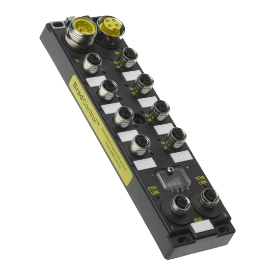
- Page 1 User’s Manual HarshIO 600 eIP IP67 Digital I/O Modules for EtherNet/IP Isolated Grounding and QuickConnect Versions BradControl™ from Molex Version 2.6 March 25 , 2013 i HarshIO 600 eIP IP67 Digital I/O Modules for EtherNet/IP...
- Page 2 Although every effort has been made to ensure the accuracy of this document, all information is subject to change without notice. Molex takes no liability for any errors in this document or for direct, indirect, or consequential damage resulting from the use of this manual.
- Page 3 STATEMENT OF LIMITED WARRANTY BradControl™ from Molex, manufacturer of HarshIO products, warrants to Buyer that products, except software, manufactured by BradControl™ will be free from defects in material and workmanship. BradControl™ obligation under this warranty will be limited to repairing or replacing the defective parts within one year of the date of installation.
-
Page 4: Table Of Contents
Table of contents General Safety Instructions ..............6 General information ....................6 Personnel qualifications ..................6 Preventive messages ....................6 Usage compliance ....................6 Device installation and set-up ................. 7 Device operation ..................... 8 Electrical, mechanical and thermal specifications ........... 8 Preventive and corrective maintenance .............. - Page 5 Configuration using RSLogix 5000 ..........57 ESD File ........................ 57 Commissionning HarshIO eIP in Rockwell Logix 5000 version 20 ....... 58 Commissionning HarshIO eIP in Rockwell Logix 5000 version 17 ....... 74 Web Server Interface ................. 76 IP and Physical information ................... 77 Network Interface information ................
-
Page 6: General Safety Instructions
1. General Safety Instructions General information The current documentation is intended for persons technically qualified to install, use and service the products described herein. It contains the necessary information for proper use of the products. However, for advanced use of our products, please contact your nearest dealer for additional information. The content of this documentation is not binding and cannot extend or limit warranties. -
Page 7: Device Installation And Set-Up
intended as described in the documentation, and with approved products. As a general rule, if all the handling, transportation, and storage recommendations and installation, operation and maintenance instructions are followed, the products will operate correctly without risk for personnel or hardware. -
Page 8: Device Operation
Device operation Because Brad™ HarshIO devices are components of a control system, the safety of the entire automated system, including that of the installation and the application, cannot be dealt with in this document. For further information, see IEC 1131-4, describing risk reduction measures for PLC users. See the documentation of the specific products involved for more information on operation safety. -
Page 9: General Description
® All BradControl™ HarshIO modules with Micro-Change (M12) ports accept both threaded cordsets and Molex Ultra-Lock™ system. Ultra-Lock™ connection System! The fastest, easiest and most secure connection ever designed. Ultra-Lock™ technology is designed for higher performance and reliability. Discover how the push-to-lock technology of the Ultra-Lock connection system can eliminate your downtime, increase your productivity and lower your costs. - Page 10 Part Number Table 4-pin power connector versions SAP No Material No Description IP67 module for EtherNet/IP, 4-pin power supply connector, 112095-5040 TCDEI-8D0P-DYU-G 16 PNP Inputs, Isolated grounding and QuickConnect IP67 module for EtherNet/IP, 4-pin power supply connector, 112095-5041 TCDEI-888P-DYU-G 8 PNP Inputs + 8 Outputs, Isolated grounding and QuickConnect IP67 module for EtherNet/IP, 4-pin power supply connector, 112095-5043...
-
Page 11: System Description
3. System Description Overview HarshIO eIP modules can be used with a protocol compliant scanner as part of control system architecture. The modules’ built-in unmanaged 2-port Ethernet switch allows you to use the network topology that meets your application needs. These topologies include the following: ... - Page 12 Daisy-chain topology You can create a daisy-chain topology by using the module’s embedded switch ports to connect a series of up to 8 HarshIO eIP modules. NOTE: When considering the daisy chain topology, note that: Performing maintenance on any module not physically located at the end of the daisy chain – for example, by removing the network cable, or by cycling power to the module –...
- Page 13 Combination of star and daisy-chain topology Combining star and daisy-chain topology allows you to connect HarshIO eIP modules with mixed HarshIO modules or additional equipments. 13 HarshIO 600 eIP IP67 Digital I/O Modules for EtherNet/IP...
-
Page 14: Typical Application
Typical application This diagram shows you an example of a typical application using in-cabinet PLC controlling HarshIO eIP modules mount on various industrial systems. 14 HarshIO 600 eIP IP67 Digital I/O Modules for EtherNet/IP... -
Page 15: Quick Connect Applications
Quick Connect applications The HarshIO eIP modules are designed to support the new Quick Connect feature according the ODVA specifications which allow to power up, connect an EtherNet/IP scanner and start I/O cyclic data exchange in less than 500 msec. The Quick Connect feature is typically used in robotic application where some I/O devices are mounted on a tool changer. - Page 16 Enabling Quick Connect mode The HarshIO eIP modules can be configured for Quick Connect mode according the 2 methods: 1. Set Byte 9, Bit 0 of the configuration assembly (see chapter I/O Data Mapping). a value of “0” automatically disables Quick Connect sets ETH1 and ETH2 Ethernet ports to autonegociation and Auto-MDIX a value of “1”...
- Page 17 Caution: If method 2 is used, don’t forget to set to “0” the Configuration Assembly data size (see chapter I/O Data Mapping) to avoid overwriting the Quick Connect Attribute during the I/O connection with the EtherNet/IP scanner (Forward Open request). Note: After each change of Quick Connect mode (means enable ...
-
Page 18: Module Characteristics
4. Module Characteristics Hardware characteristics Type 16x INPUTS 16x OUTPUTS TCDEI-8D0P-DYU-G (4-pin power version) TCDEI-80DP-DYU-G (4-pin power version) Product Reference TCDEI-8D0P-D1U-G (5-pin power version) TCDEI-80DP-D1U-G (5-pin power version) Power Mini Change (7/8”), 4-pin or 5-pin, male, stainless steel, Maximum 8 A Power IN connector Mini Change (7/8”), 4-pin or 5-pin, female, stainless steel, Maximum 8 A Power OUT connector... - Page 19 Type 12x INPUTS + 4x OUTPUTS 8x INPUTS + 8x OUTPUTS TCDEI-8B4P-DYU-G (4-pin power version) TCDEI-888P-DYU-G (4-pin power version) Product Reference TCDEI-8B4P-D1U-G (5-pin power version) TCDEI-888P-D1U-G (5-pin power version) Power Mini Change (7/8”), 4-pin or 5-pin, male, stainless steel, Maximum 8 A Power IN connector Mini Change (7/8”), 4-pin or 5-pin, female, stainless steel, Maximum 8 A Power OUT connector...
- Page 20 Fieldbus Ethernet connectors M12, 4-pin, female, D-Coded, stainless steel, shielded IP setting DHCP based on MAC (infinite lease), Static IP EtherNet/IP Adapter according specification Vol 1-3.9 (CIP) and Vol 2 – 1.10 (EtherNet/IP) Protocol Data access Implicit messages for I/O data transfer ...
- Page 21 Mechanical Housing dimension 600 x 220 x 20 mm (2.36"x8.66"x.780") Housing material PBT VALOX 420 SEO Black 7701 Flammability Standard UL 94 V-0 Corner mounting hole 4 mounting holes, 5 x10 mm 1 mounting hole, 4.45 mm Central mounting hole Yes, stainless steel (allows the continuity of the ground when the module is mounted on the chassis Ground stud machine)
-
Page 22: Mechanical Characteristics
Mechanical characteristics Size and dimensions (in mm) 60 , 0 37,1 3 8, 0 4,45 ETH1 ETH2 LINK LINK 2 0 ,0 5x10 3 1 ,5 22 HarshIO 600 eIP IP67 Digital I/O Modules for EtherNet/IP... -
Page 23: Physical I/O Mapping
Physical I/O mapping 16x Inputs (4-pin power connector) 16x Inputs (5-pin power connector) ETH1 ETH2 ETH1 ETH2 LINK LINK LINK LINK 23 HarshIO 600 eIP IP67 Digital I/O Modules for EtherNet/IP... - Page 24 12x Inputs + 4x Outputs (4-pin power connector) 12x Inputs + 4x Outputs (5-pin power connector) ETH1 ETH2 ETH1 ETH2 LINK LINK LINK LINK 24 HarshIO 600 eIP IP67 Digital I/O Modules for EtherNet/IP...
- Page 25 8x Inputs + 8x Outputs (4-pin power connector) 8x Inputs + 8x Outputs (5-pin power connector) ETH1 ETH2 ETH1 ETH2 LINK LINK LINK LINK 25 HarshIO 600 eIP IP67 Digital I/O Modules for EtherNet/IP...
- Page 26 16x Outputs (4-pin power connector) 16x Outputs (5-pin power connector) ETH1 ETH2 ETH1 ETH2 LINK LINK LINK LINK 26 HarshIO 600 eIP IP67 Digital I/O Modules for EtherNet/IP...
-
Page 27: I/O Messaging
I/O messaging The firmware embedded in the HarshIO 600 eIP supports up to a maximum of 8 I/O connections. Fewer connections allow faster data I/O update rates (RPI value). I/O Connections: Module supports 2 Transport Class 1 I/O connections (Cyclic and Change-Of-State triggers): 1x Exclusive Owner ... -
Page 28: I/O Data Mapping
I/O data mapping The I/O process data are available through the EtherNet/IP assemblies: Assembly #103 for Input process data Assembly #104 for Output process data Assembly #106 for Configuration data Note: The data size can be set to “0” if the scanner doesn’t need to send Configuration data at the establishment of the connection (Forward Open request). - Page 29 16 Inputs module versions Byte Bit 15 Bit 14 Bit 13 Bit 12 Bit 11 Bit 10 Bit 9 Bit 8 Bit 7 Bit 6 Bit 5 Bit 4 Bit 3 Bit 2 Bit 1 Bit 0 Offset Input Data (Assembly #103), Size: 8 bytes Diag Data Input Data...
- Page 30 16 Outputs module versions Byte Bit 15 Bit 14 Bit 13 Bit 12 Bit 11 Bit 10 Bit 9 Bit 8 Bit 7 Bit 6 Bit 5 Bit 4 Bit 3 Bit 2 Bit 1 Bit 0 Offset Input Data (Assembly #103), Size: 8 bytes Diag Diag Data...
- Page 31 All Outputs activated have Port Status (CS Ox) bit set to 1 Set to 0, if UL is > 18.1 VDC All Outputs activated are energized All Outputs activated have diagnostic leds to GREEN All Outputs activated have Port Status (CS Ox) bit set to 0 ...
- Page 32 12 Inputs + 4 Outputs module versions Byte Bit 15 Bit 14 Bit 13 Bit 12 Bit 11 Bit 10 Bit 9 Bit 8 Bit 7 Bit 6 Bit 5 Bit 4 Bit 3 Bit 2 Bit 1 Bit 0 Offset Input Data (Assembly #103), Size: 8 bytes Diag...
- Page 33 Diag UL: Diagnostic Output power supply (UL) Set to 1, if UL is < 17.6 VDC All Outputs activated are de-energized All Outputs activated have diagnostic leds to RED All Outputs activated have Port Status (CS Ox) bit set to 1 ...
- Page 34 8 Inputs + 8 Outputs module versions Byte Bit 15 Bit 14 Bit 13 Bit 12 Bit 11 Bit 10 Bit 9 Bit 8 Bit 7 Bit 6 Bit 5 Bit 4 Bit 3 Bit 2 Bit 1 Bit 0 Offset Input Data (Assembly #103), Size: 8 bytes Diag...
- Page 35 Diag UL: Diagnostic Output power supply (UL) Set to 1, if UL is < 17.6 VDC All Outputs activated are de-energized All Outputs activated have diagnostic leds to RED All Outputs activated have Port Status (CS Ox) bit set to 1 ...
-
Page 36: Pin Assignment
Pin assignment 4-pin power supply versions Power IN Wiring Information : Power OUT 1 - 24 VDC (Outputs Power) 4-pole, 7/8 (Mini-Change), Male 4-pole, 7/8 (Mini-Change), Female 2 - 24 VDC (Module & Inputs Power) 3 - 0 V (Ground Module & Inputs Power) 4 - 0 V (Outputs Power) I/O Ports 5-pole, M12 (Micro-Change),... - Page 37 5-pin power supply versions Wiring Information : 1 - 0 V (Outputs Power) Power IN Power OUT 2 - 0 V (Module & Inputs Power) 5-pole, 7/8 (Mini-Change), Male 5-pole, 7/8 (Mini-Change), Female 3 - PE (Protected Earth) 4 - 24 VDC (Module & Inputs Power) 5 - 24 VDC (Outputs Power) Input Ports Output Ports...
-
Page 38: Separate Grounding Wiring For Application Using Safety Relays
Separate grounding wiring for application using safety relays The HarshIO 600 power connector includes a separate grounding isolation between the input/logic ground and the output ground. This feature allows powering the module with 2 distinct power supplies that is commonly used in safety application. Typically in automation application, a system designer is using safety relays (like Rockwell Automation Guard I/O EtherNet/IP Safety Modules [1791ES-IB8XOBV4, 1791ES-IB16], Siemens PM-E F pp DC24V [6ES7 138-4CF42-0AB0], Siemens PM-E F pm DC24V [6ES7 138-4CF03-0AB0]) that regularly perform the... - Page 39 However if the separate grounding for safety is not required by the system designer, the HarshIO modules can operate using a single ground for both logic/input and output. Architecture using a single ground Note, the connection of the common ground (Logic/Input + Output) is made outside the HarshIO module.
-
Page 40: Port Wiring Type
Port wiring type 2 Input channels per port – Twin wired Note: PNP wiring with a 2 wires input sensor Connect pin 1 (24 V) and pin 4 or 2 (signal in) 2 Output channels per port – Twin wired ... -
Page 41: Led Assignment
LED assignment In-coming Bus Power Connector (Ui) Out-coming Bus Power Connector (Uo) Use this connector to power the module. Use this connector to daisy-chain the power to an additional HarshIO eIP module Outputs Power LED (UL) Module & Inputs power LED (UB) Green: Auxiliary Power supplied Green: Auxiliary Power supplied Off: Auxiliary Power not supplied... -
Page 42: Network Ip Address Setting
Network IP address setting The HarshIO 600 eIP is configured in DHCP mode by default. When connecting to a network with a DHCP server, an IP address is automatically assigned to the module. You can stop the DHCP procedure (in case of no DHCP server on the network) by touching the push-buttons located in the Window area of the module . - Page 43 2. Use Molex EtherNet/IP Tools To change the IP settings of the module, you have to use a software tool like Molex EtherNet/IP Tools that manages Explicit Messaging requests to access module CIP objects (0xF5 TCP/IP 0xF6 Ethernet Link) to set parameters like:...
- Page 44 Click on F5 TCP/IP tab and then on Get_Attribute_All. The device parameters are displayed. For example to modify the IP Address parameter, write the new IP and select Set_Attribute button to send the command. 44 HarshIO 600 eIP IP67 Digital I/O Modules for EtherNet/IP...
-
Page 45: Display Information
Display information The 4-digit LED display shows the Ethernet configuration and the global state of the module. Information present into the display: Module information NEED RESET: Means that the module requires a reset via software (using CIP Identity object) or a power cycle ... -
Page 46: Hardware Address (Mac Address)
00.A0.91 X.XX.XX EDS files The EDS files can be downloaded from the Molex website: http://www.molex.com/molex/mysst/DownloadCenter.action Configure the HarshIO 600 eIP via the EDS file. In this EDS file, the HarshIO 600 eIP is implemented as standard device in your system. -
Page 47: Specific Behavior
5. Specific Behavior I/O behavior When the HarshIO 600 eIP is running (Scanner connection in progress) if the module detects a connection lost with the Scanner, the module sets automatically the output process data to 0. The detection of the connection lost with the Scanner is calculated based on the time-out (multiplier x RPI) defined in the I/O connection (Forward_Open request) sent by the scanner. -
Page 48: Ethernet/Ip Object Classes
EtherNet/IP Object Classes The following services are accessible through the use of EtherNet/IP Explicit Messaging. Identity (0x01) This object allows reading the identity of the module. Class Attributes Description Limits 1 Revision 1 Max Instance ... -
Page 49: Message Router (0X02)
Message Router (0x02) Class Attributes Description Limits Revision Optional Attribute List Optional Service List Max ID of class attributes Max ID of instance attributes Supported Not Supported Class Services Service Param. -
Page 50: Assembly (0X04)
Assembly (0x04) This object allows to access I/O process data. Class Attributes Description Limits 2 Revision 199 Max Instance 4 Number of instances Supported Not supported Class Services Service Param. Options Get_Attribute_Single ... -
Page 51: Connection Manager (0X06)
Connection Manager (0x06) Class Attributes Description Limits 1 Revision 1 Max Instance 1 Number of instances Supported Not supported Class Services Service Param. Options Get_Attributes_All Get_Attribute_Single Instance Attributes Description Limits Open Requests ... -
Page 52: Tcp/Ip Interface (0Xf5)
TCP/IP Interface (0xF5) Class Attributes Description Limits 2 Revision 1 Max Instance 1 Number of instances Supported Not supported Class Services Service Param. Options Get_Attributes_All Get_Attribute_Single Instance Attributes Description Limits Status ... -
Page 53: Ethernet Link (0Xf6)
Ethernet Link (0xF6) Class Attributes Description Limits 3 Revision 3 Max Instance 3 Number of Instance Supported Not supported Class Services Service Param. Options Get_Attributes_All Get_Attribute_Single Instance Attributes Description Limits Interface Speed ... -
Page 54: Getting Started
Quantity Manufacturer Devices Programmable controller processor with EtherNet/IP scanner port TCDEI-8D0P-DYU-G TCDEI-888P-DYU-G TCDEI-8B4P-DYU-G TCDEI-80DP-DYU-G HarshIO 600 eIP BradControl from Molex TCDEI-8D0P-D1U-G TCDEI-888P-D1U-G TCDEI-8B4P-D1U-G TCDEI-80DP-D1U-G Network communication From Scanner to HarshIO module EWWA06003Mxy0* M12 Ultra-Lock™ (male D-coded) straight BradControl from Molex... -
Page 55: Getting Started
Getting Started 1. I/O wiring and connect Wire the inputs and/or outputs according to the drawings of chapter "Port wiring type" by using M12/Ultra-Lock (A-code) connectors. Depending on the model reference, the same I/O port supports two I/O channels (2 inputs or 2 outputs) according to I/O assignment. Only one M12/Ultra-Lock (A-code) connector is needed for two I/Os. - Page 56 I/O Status LED State Status Description Recommended action Output not powered and no Output is not powered or input is not None if not used valid input valid Check I/O wire pining Output powered and valid Green – Solid ON Output is powered and input is valid None input...
-
Page 57: Configuration Using Rslogix 5000
Before proceeding to the product commissioning, the HarshIO modules require a description file (also called EDS file) that has to be imported in the Rockwell Automation RSLogix™ 5000 software. The EDS file as well as the product documentation can be downloaded from the Molex web site. http://www.molex.com/molex/mysst/DownloadCenter.action and use option 1 –... -
Page 58: Commissionning Harshio Eip In Rockwell Logix 5000 Version 20
Commissionning HarshIO eIP in Rockwell Logix 5000 version 20 1. Import HarshIO eIP EDS file into Rockwell hardware library To start the commissioning, the first step is to import the HarshIO 600 eIP EDS file into Rockwell hardware library by using Rockwell Automation RSLinx™ software. Start RA RSLinx software. - Page 59 Select Menu Communications/Configure Drivers… Select EtherNet/IP Driver 59 HarshIO 600 eIP IP67 Digital I/O Modules for EtherNet/IP...
- Page 60 Set a name for the Driver. If you have multiple network interfaces in your computer, select the correct one to communicate with the HarshIO eIP module. 60 HarshIO 600 eIP IP67 Digital I/O Modules for EtherNet/IP...
- Page 61 Check that the Driver is running. RSLinx is now browsing the network to detect the EtherNet/IP devices. At this stage, the HarshIO eIP module is detected but appears with an icon representing a question mark because the EDS file is not yet imported. ...
- Page 62 Select the HarshIO module, right-click on mouse and select Upload EDS file from device A new tool is launch. Select Next button. 62 HarshIO 600 eIP IP67 Digital I/O Modules for EtherNet/IP...
- Page 63 The EDS Wizard is checking the EDS file revision in the device. The EDS Wizard is checking integrity of the EDS file. 63 HarshIO 600 eIP IP67 Digital I/O Modules for EtherNet/IP...
- Page 64 The EDS Wizard is checking integrity of the icon file. The EDS Wizard is importing the EDS file and icon in the Rockwell hardware library. 64 HarshIO 600 eIP IP67 Digital I/O Modules for EtherNet/IP...
- Page 65 The EDS Wizard has successfully import the files. RSlinx has registered correctly the EDS file and display the correct icon of the HarshIO eIP module. 65 HarshIO 600 eIP IP67 Digital I/O Modules for EtherNet/IP...
- Page 66 2. Add HarshIO eIP module into Rockwell RSLogix 5000 software Start RSLogix 5000 software. Select the Ethernet node of the EtherNet/IP connectivity channel. Right-click on mouse and select New Module… 66 HarshIO 600 eIP IP67 Digital I/O Modules for EtherNet/IP...
- Page 67 Look and select in the Catalog the HarshIO eIP module. Select the module, right-click on mouse and select Create 67 HarshIO 600 eIP IP67 Digital I/O Modules for EtherNet/IP...
- Page 68 Give a Name and set the module IP address. Note: The IP address can be obtain by looking the scrolling display on the module. 68 HarshIO 600 eIP IP67 Digital I/O Modules for EtherNet/IP...
- Page 69 Select the module RPI, the I/O connection type (Unicast or Multicast) and the exchange mode (Cyclic or Change-of-State) . Note: The HarshIO eIP module supports RPI up to 1ms packet interval. Note: Remember a RPI set at 1ms generate 2000 packets per second (1000x packets from Scanner to HarshIO + 1000x packets from HarshIO to Scanner) ...
- Page 70 The HarshIO module is now configured and in the EtherNet/IP scan list. Download the new project in the controller CPU. Go online and check the HarshIO module communication status. 70 HarshIO 600 eIP IP67 Digital I/O Modules for EtherNet/IP...
- Page 71 3. Modifying HarshIO eIP module parameters in RSLogix 5000 software Go online and double click on HarshIO eIP module. Select Module Info tab to display HarshIO module information. 71 HarshIO 600 eIP IP67 Digital I/O Modules for EtherNet/IP...
- Page 72 Select Internet Protocol tab to setup IP address settings of HarshIO module information. 72 HarshIO 600 eIP IP67 Digital I/O Modules for EtherNet/IP...
- Page 73 Select Port Configuration tab to setup HarshIO Ethernet ports of the integrated 2-port switch. 73 HarshIO 600 eIP IP67 Digital I/O Modules for EtherNet/IP...
-
Page 74: Commissionning Harshio Eip In Rockwell Logix 5000 Version 17
Commissionning HarshIO eIP in Rockwell Logix 5000 version 17 The first step is to add a HarshIO 600 eIP in the configuration of a Rockwell Scanner supporting EtherNet/IP by selecting "ETHERNET-MODULE" (Generic Ethernet Module) device as shown below. 74 HarshIO 600 eIP IP67 Digital I/O Modules for EtherNet/IP... - Page 75 In the configuration of the "ETHERNET-MODULE", set the parameters of the HarshIO 600 eIP with the following properties: Instance numbers Size of each parameter IP address of HarshIO Connection Parameters: Input: Assembly: 103 Size (in 16-bit word): 4 See chapter I/O Data Mapping for input data mapping details.
-
Page 76: Web Server Interface
9. Web Server Interface The web server interface offers the user a convenient and simple method for the diagnosis of HarshIO 600 eIP thru a web browser (Internet Explorer, Firefox, etc…). To do so: Connect your computer to the HarshIO module ... -
Page 77: Ip And Physical Information
IP and Physical information This page shows the main information about the selected HarshIO module. 77 HarshIO 600 eIP IP67 Digital I/O Modules for EtherNet/IP... -
Page 78: Network Interface Information
Network Interface information This page shows the current status of the Ethernet switch ports. 78 HarshIO 600 eIP IP67 Digital I/O Modules for EtherNet/IP... -
Page 79: Ethernet/Ip Information
EtherNet/IP information This page shows the current connexion status (in relation with the EtherNet/IP Scanner) of the HarshIO module. The Status of the module could be: IO connection received (OPERATE) Connection lost (TIMEOUT) Connection closed (CLOSE) No connection (NO_CNX) ... -
Page 80: Earth Connection
10. Earth Connection At least one of the earth connections shown on the schematics must be ground connected to ensure the good operation of the module. Use a plastic stick to press button or wear anti-static equipment. ETH1 ETH2 LINK LINK Figure 9_1 ... - Page 81 If the earth connection is done by one of the Ethernet cable, in order to avoid noise loop it is important to not connect other earth connection of the module to the ground (See Figure 9_2). Ethernet Ethernet Ethernet Switch or PLC Device Device Ethernet...
-
Page 82: Cables And Cordsets
11. Cables and Cordsets BradConnectivity™ is part of Molex as well as BradControl™ and is specialized in the manufacturing of connectors, cordsets and distribution boxes for sensors, actuators and bus network applications. BradConnectivity™ provides a wide range of product references among which: Industrial Ethernet cables ®... - Page 83 Female-to-Male (Straight) Cable option: 03 – Unshielded PVC 10 – Shielded PUR 15 – Shielded PVC ® M12 Single-Ended Cordsets – Order Number Brad Cable option: 03 – Unshielded PVC 05 – Shielded TPE 10 –...
- Page 84 ® M12 Double-Ended Cordsets – Order Number Brad Male to Male Cable option: 03 – Unshielded PVC 04 – Unshielded TPE 05 – Shielded TPE 10 – Shielded PUR 15 – Shielded PVC 84 HarshIO 600 eIP IP67 Digital I/O Modules for EtherNet/IP...
- Page 85 ® M12 Double-Ended Cordsets – Order Number Brad Female to Male Cable option: 03 – Unshielded PVC 15 – Shielded PVC ® ® (M12) Field Attachable Connectors – Order Number Brad Micro-Change 85 HarshIO 600 eIP IP67 Digital I/O Modules for EtherNet/IP...
- Page 86 ® ® (M12) Receptacles – Order Number Brad Micro-Change Female Female 86 HarshIO 600 eIP IP67 Digital I/O Modules for EtherNet/IP...
- Page 87 ® ® (M12) Bulkhead Pass-Through Adapters – Order Number Brad Micro-Change 87 HarshIO 600 eIP IP67 Digital I/O Modules for EtherNet/IP...
-
Page 88: I/O Cables
I/O cables ® Ultra-Lock™ (M12) Single-Ended Cordsets – Order Number Brad Cable option: E03 – Yellow PVC P03 – Black PUR/PVC, 0.34mm² K05 – Yellow TPE flex life (torsion and bending) P02 – Black PUR/PVC, 0.25mm² ... - Page 89 ® Ultra-Lock™ (M12) Field attachable connectors – Order Number Brad 89 HarshIO 600 eIP IP67 Digital I/O Modules for EtherNet/IP...
- Page 90 ® ® (M12) Splitter cordsets – Order Number Brad Ultra-Lock Cable option: E03 – Yellow PVC P03 – Black PUR/PVC, 0.34mm² K05 – Yellow TPE flex life (torsion and bending) 90 HarshIO 600 eIP IP67 Digital I/O Modules for EtherNet/IP...
- Page 91 ® ® (M12) Single-Ended cordsets – Order Number Brad Micro-Change Cable option: E03 – Yellow PVC P03 – Black PUR/PVC K05 – Yellow TPE flex life (torsion and bending) 91 HarshIO 600 eIP IP67 Digital I/O Modules for EtherNet/IP...
- Page 92 ® ® (M12) Double-Ended cordsets – Order Number Brad Micro-Change Cable option: E03 – Yellow PVC P03 – Black PUR/PVC K05 – Yellow TPE flex life (torsion and bending) 92 HarshIO 600 eIP IP67 Digital I/O Modules for EtherNet/IP...
- Page 93 ® Ultra-Lock™ (M12) Field attachable connectors – Order Number Brad 93 HarshIO 600 eIP IP67 Digital I/O Modules for EtherNet/IP...
-
Page 94: Power Supply Cables
Power supply cables ® ® Single-Ended Cordsets – Order Number Brad Mini-Change Male Female 94 HarshIO 600 eIP IP67 Digital I/O Modules for EtherNet/IP... - Page 95 ® ® Double-Ended Cordsets – Order Number Brad Mini-Change 95 HarshIO 600 eIP IP67 Digital I/O Modules for EtherNet/IP...
-
Page 96: Product Support
Your HarshIO 600 identification is located on the backside of the device. Module Type Product Version Serial Number MAC Address Technical Support To assist users in using the products, Molex provides technical information on its web site: Molex Support and Download They can find particularly: Downloads center ... - Page 97 BradControl™ from Molex 41, rue Mazagran 76320 Caudebec-lès-Elbeuf FRANCE 97 HarshIO 600 eIP IP67 Digital I/O Modules for EtherNet/IP...
Need help?
Do you have a question about the BradControl HarshIO 600 eIP and is the answer not in the manual?
Questions and answers