
Related Manuals for molex SST-PB3-REM


Summary of Contents for molex SST-PB3-REM
- Page 1 SST™ Profibus Remote Module SST-PB3-REM User Reference Guide Document Edition: 1.1.4.0 Document #: 715-0106...
- Page 2 1.1.4.0 site ©2014 Molex Inc. Document Edition: 1.1.4.0, Document #: 715-0106, Template Edition: 1.1, Template #: QMS-06-045 Use, duplication or disclosure of this document or any of the information contained herein is subject to the restrictions on page ii of this document.
- Page 3 User Reference Guide COPYRIGHTS and TRADEMARKS This document and its contents are the proprietary and confidential property of Molex Inc. and/or its related companies and may not be used or disclosed to others without the express prior written consent of Molex Inc. and/or its related companies.
- Page 4 User Reference Guide SST-PB3-REM ©2014 Molex Inc. Document Edition: 1.1.4.0, Document #: 715-0106, Template Edition: 1.1, Template #: QMS-06-045 Use, duplication or disclosure of this document or any of the information contained herein is subject to the restrictions on page ii of this document.
-
Page 5: Table Of Contents
Equipment and Tools ......................26 Hardware Features ...................... 27 Introduction ........................28 System LEDs ........................30 Ethernet LEDs ........................33 Setting the IP Address, Rotary Switches ................35 SST-PB3-REM Module Mounting ...................37 Ground Connection......................38 Profibus Connection ......................39 Ethernet Connection ......................41 Power Supply ........................42 Contents ©2014 Molex Inc. - Page 6 Electrical Characteristics ....................44 3.11 Hardware Standards ......................45 3.12 Condition of Use ......................46 Software Features ....................... 47 Introduction ........................48 Configuring SST-PB3-REM as a DP-V0 Master .............49 4.2.1 Communication Path Configuration ................59 4.2.2 Master Parameters Configuration ................61 4.2.3 Device Data Area Configuration ................63 4.2.4...
- Page 7 Registering EDS file via EDS Hardware Installation Tool ........112 Changing the Ethernet Port Configuration of the SST-PB3-REM in RSlinx....117 Configuring the SST-PB3-REM in Studio 5000 V21 using EDS AOP (Add-On-Profile)120 5.5.1 Configuring Remote Module as DP Master only via EDS AOP ......124 5.5.2...
- Page 8 9.2.9 Disable / Enable Slave .....................197 9.2.10 Set Slave Address ....................198 9.2.11 Basic Diagnostics ....................199 Sending an Explicit Message to SST-PB3-REM in RSLogix5000 ........201 RSLogix5000 Ladder Samples ................. 207 10.1 Ladder Sample Overview ....................208 10.2 DP-V0 Master Ladder Sample ..................208 10.3...
-
Page 9: Preface
• Preface ©2014 Molex Inc. Document Edition: 1.1.4.0, Document #: 715-0106, Template Edition: 1.1, Template #: QMS-06-045 Use, duplication or disclosure of this document or any of the information contained herein is subject to the restrictions on page ii of this document. - Page 10 SST-PB3-REM Purpose of this Guide This manual is a user's guide for the SST-PB3-REM Profibus Remote Module. Use this guide if you are responsible for installing, programming or troubleshooting control systems that use Allen-Bradley Logix™ processors with SST-PB3-REM. It is assumed that you have a basic understanding of PLCs and are familiar with Profibus modules and the Profibus network.
- Page 11 RSLogix5000 User-Defined Data Type. Preface ©2014 Molex Inc. Document Edition: 1.1.4.0, Document #: 715-0106, Template Edition: 1.1, Template #: QMS-06-045 Use, duplication or disclosure of this document or any of the information contained herein is subject to the restrictions on page ii of this document.
- Page 12 SST-PB3-REM Preface ©2014 Molex Inc. Document Edition: 1.1.4.0, Document #: 715-0106, Template Edition: 1.1, Template #: QMS-06-045 Use, duplication or disclosure of this document or any of the information contained herein is subject to the restrictions on page ii of this document.
-
Page 13: System Overview
Module States System Overview ©2014 Molex Inc. Document Edition: 1.1.4.0, Document #: 715-0106, Template Edition: 1.1, Template #: QMS-06-045 Use, duplication or disclosure of this document or any of the information contained herein is subject to the restrictions on page ii of this document. -
Page 14: Key Features
User Reference Guide SST-PB3-REM 1.1 Key Features The SST-PB3-REM is a linking device designed to provide Profibus DP-V0 and DP-V1 Master / Slave capability to Rockwell Automation Logix™ systems via EtherNet/IP. Figure 1.1-1: SST™ PB3 Remote Module Typical Application Key features: •... -
Page 15: How It Works
Class-2: MSAC2_Initiate, MSAC2_Read, MSAC2_Write, MSAC2_Abort 1.2 How It Works SST-PB3-REM combines the functionality of an EtherNet/IP Adapter with that of a Profibus Master or/and Slave which enables a controller acting as an EtherNet/IP Scanner to transmit and receive data on the Profibus network. -
Page 16: Ethernet/Ip Assemblies Overview
, Slave Functionality for more details. 1.3 EtherNet/IP Assemblies Overview Internal to the SST-PB3-REM, Profibus data is mapped to EtherNet/IP I/O assemblies. When the module is configured as a Profibus Master, data mapping is automatically handled by the SST™ Profibus Configuration Tool at the time when the configuration is created. Based on the Profibus configuration, the user must configure at least one or up to five Exclusive Owner connections as seen in Table 2.3-1: Exclusive Owner Connections. - Page 17 (**): By default this value should be left at 0. If set to 8, configuration data must match configuration data from the first Exclusive Owner connection. Listen-only connection refers to a connection that is made to an SST-PB3-REM module that is already configured with an Exclusive Owner connection from the main controller. A Listen-only connection allows inputs on an SST-PB3-REM module to be monitored from another controller.
-
Page 18: Profibus To Ethernet/Ip Data Mapping
SST™ Profibus Configuration Tool, for detail on variable naming see section System Overview ©2014 Molex Inc. Document Edition: 1.1.4.0, Document #: 715-0106, Template Edition: 1.1, Template #: QMS-06-045 Use, duplication or disclosure of this document or any of the information contained herein is subject to the restrictions on page ii of this document. -
Page 19: Explicit Messaging Overview
This file may be later imported into an Excel spreadsheet. 1.5 Explicit Messaging Overview SST-PB3-REM supports two types of explicit messages: for retrieving I/O data and general messaging such as DP-V1, diagnostics data etc. Reading and writing I/O data may be useful when the originator does not have implicit messaging capabilities. -
Page 20: Pb3 State
System Overview ©2014 Molex Inc. Document Edition: 1.1.4.0, Document #: 715-0106, Template Edition: 1.1, Template #: QMS-06-045 Use, duplication or disclosure of this document or any of the information contained herein is subject to the restrictions on page ii of this document. -
Page 21: Profibus State
As a Profibus slave, the module is online on Profibus. System Overview ©2014 Molex Inc. Document Edition: 1.1.4.0, Document #: 715-0106, Template Edition: 1.1, Template #: QMS-06-045 Use, duplication or disclosure of this document or any of the information contained herein is subject to the restrictions on page ii of this document. - Page 22 1.6-3: Profibus State Transition Example System Overview ©2014 Molex Inc. Document Edition: 1.1.4.0, Document #: 715-0106, Template Edition: 1.1, Template #: QMS-06-045 Use, duplication or disclosure of this document or any of the information contained herein is subject to the restrictions on page ii of this document.
-
Page 23: Installation
Equipment and Tools Installation ©2014 Molex Inc. Document Edition: 1.1.4.0, Document #: 715-0106, Template Edition: 1.1, Template #: QMS-06-045 Use, duplication or disclosure of this document or any of the information contained herein is subject to the restrictions on page ii of this document. -
Page 24: Introduction
User Reference Guide SST-PB3-REM 2.1 Introduction The CD-ROM included in the SST-PB3-REM module packaging contains the installations for a number of different Rockwell backplane modules. To install the software for the SST-PB3-REM please follow the instructions in section 3.3, Installing the software. - Page 25 SST-PB3-REM User Reference Guide 4. Select SST-PB3-REM from the list. 5. Select SST Profibus Backplane Products Install x.x for Windows and click Install. 6. Click on Next > 7. Read the License agreement and if you agree, click the acceptance and Next >.
-
Page 26: Equipment And Tools
At a minimum, have the following tools and equipment ready: • SST-PB3-REM module • 24V power supply • Profibus cable to connect the SST-PB3-REM to the Profibus network • 2 Profibus DB-9 connectors 1 RJ45 Ethernet cable • SST™ Profibus Configuration Tool •... -
Page 27: Hardware Features
Hardware Features Chapter Sections: • Introduction • System LEDs • Ethernet LEDs • Setting the IP Address, Rotary Switches • SST-PB3-REM Module Mounting • Ground Connection Profibus Connection • Ethernet Connection • Power Supply • Electrical Characteristics • Hardware Standards •... -
Page 28: Introduction
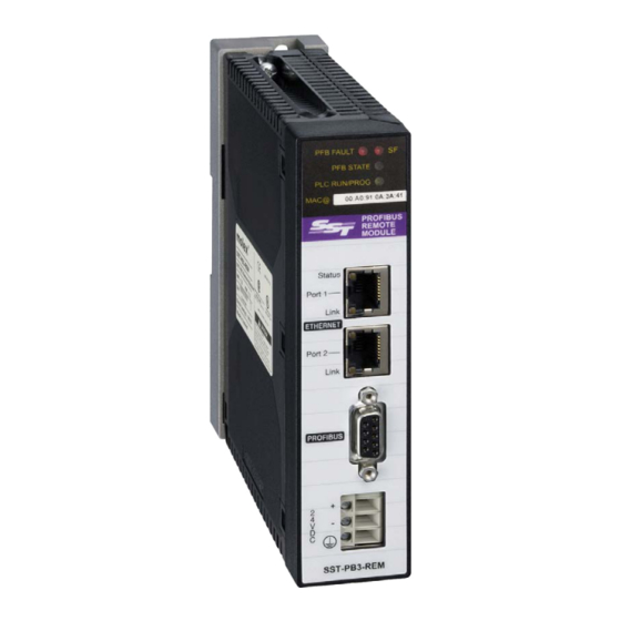
Support plate for fixing the module directly to a DIN rail Hardware Features ©2014 Molex Inc. Document Edition: 1.1.4.0, Document #: 715-0106, Template Edition: 1.1, Template #: QMS-06-045 Use, duplication or disclosure of this document or any of the information contained herein is subject to the restrictions on page ii of this document. - Page 29 Figure 1: Hardware Features ©2014 Molex Inc. Document Edition: 1.1.4.0, Document #: 715-0106, Template Edition: 1.1, Template #: QMS-06-045 Use, duplication or disclosure of this document or any of the information contained herein is subject to the restrictions on page ii of this document.
-
Page 30: System Leds
Hardware Features ©2014 Molex Inc. Document Edition: 1.1.4.0, Document #: 715-0106, Template Edition: 1.1, Template #: QMS-06-045 Use, duplication or disclosure of this document or any of the information contained herein is subject to the restrictions on page ii of this document. - Page 31 Hardware Features ©2014 Molex Inc. Document Edition: 1.1.4.0, Document #: 715-0106, Template Edition: 1.1, Template #: QMS-06-045 Use, duplication or disclosure of this document or any of the information contained herein is subject to the restrictions on page ii of this document.
- Page 32 PLC is RUN mode. Hardware Features ©2014 Molex Inc. Document Edition: 1.1.4.0, Document #: 715-0106, Template Edition: 1.1, Template #: QMS-06-045 Use, duplication or disclosure of this document or any of the information contained herein is subject to the restrictions on page ii of this document.
-
Page 33: Ethernet Leds
LED state changes to 5 Hardware Features ©2014 Molex Inc. Document Edition: 1.1.4.0, Document #: 715-0106, Template Edition: 1.1, Template #: QMS-06-045 Use, duplication or disclosure of this document or any of the information contained herein is subject to the restrictions on page ii of this document. - Page 34 Yellow Hardware Features ©2014 Molex Inc. Document Edition: 1.1.4.0, Document #: 715-0106, Template Edition: 1.1, Template #: QMS-06-045 Use, duplication or disclosure of this document or any of the information contained herein is subject to the restrictions on page ii of this document.
-
Page 35: Setting The Ip Address, Rotary Switches
SST-PB3-REM module. Once the module is mounted, they will no longer be accessible. The primary role of the rotary switches is to define the SST-PB3-REM IP address assignment modes. • DHCP based on MAC address •... - Page 36 Hardware Features ©2014 Molex Inc. Document Edition: 1.1.4.0, Document #: 715-0106, Template Edition: 1.1, Template #: QMS-06-045 Use, duplication or disclosure of this document or any of the information contained herein is subject to the restrictions on page ii of this document.
-
Page 37: Sst-Pb3-Rem Module Mounting
SST-PB3-REM User Reference Guide 3.5 SST-PB3-REM Module Mounting At a glance Using its support plate, the SST-PB3-REM module may be installed as a standalone module on a DIN rail, grid or panel. Support plate Label Meaning Two holes of diameter 5.5 mm (7/32 in) allowing the support plate to be fixed to a panel or to an AM1-PA pre- slotted plate, with a centerline distance of 140 mm (5.51... -
Page 38: Ground Connection
Hardware Features ©2014 Molex Inc. Document Edition: 1.1.4.0, Document #: 715-0106, Template Edition: 1.1, Template #: QMS-06-045 Use, duplication or disclosure of this document or any of the information contained herein is subject to the restrictions on page ii of this document. -
Page 39: Profibus Connection
Not connected Hardware Features ©2014 Molex Inc. Document Edition: 1.1.4.0, Document #: 715-0106, Template Edition: 1.1, Template #: QMS-06-045 Use, duplication or disclosure of this document or any of the information contained herein is subject to the restrictions on page ii of this document. - Page 40 Cable stripping tool. Hardware Features ©2014 Molex Inc. Document Edition: 1.1.4.0, Document #: 715-0106, Template Edition: 1.1, Template #: QMS-06-045 Use, duplication or disclosure of this document or any of the information contained herein is subject to the restrictions on page ii of this document.
-
Page 41: Ethernet Connection
TIA-EIA-568A. Hardware Features ©2014 Molex Inc. Document Edition: 1.1.4.0, Document #: 715-0106, Template Edition: 1.1, Template #: QMS-06-045 Use, duplication or disclosure of this document or any of the information contained herein is subject to the restrictions on page ii of this document. -
Page 42: Power Supply
Connection connected to the SST-PB3-REM chassis. The SST-PB3-REM module must be powered by an external 24VDC industrial power supply unit which must be compliant with the characteristics in section 4.10, Electrical Characteristics. The power supply must be local: cable length < 30 m. - Page 43 (size 0.6 x 3.5 mm). Set Power ON Power-up the power supply module. The SST-PB3-REM module LEDs will light up to indicate that the power is on and the module is booting (approximately 30 s). Hardware Features ©2014 Molex Inc.
-
Page 44: Electrical Characteristics
Hardware Features ©2014 Molex Inc. Document Edition: 1.1.4.0, Document #: 715-0106, Template Edition: 1.1, Template #: QMS-06-045 Use, duplication or disclosure of this document or any of the information contained herein is subject to the restrictions on page ii of this document. -
Page 45: Hardware Standards
Hardware Features ©2014 Molex Inc. Document Edition: 1.1.4.0, Document #: 715-0106, Template Edition: 1.1, Template #: QMS-06-045 Use, duplication or disclosure of this document or any of the information contained herein is subject to the restrictions on page ii of this document. -
Page 46: Condition Of Use
• Relative humidity : 10-95% (non-condensing) Hardware Features ©2014 Molex Inc. Document Edition: 1.1.4.0, Document #: 715-0106, Template Edition: 1.1, Template #: QMS-06-045 Use, duplication or disclosure of this document or any of the information contained herein is subject to the restrictions on page ii of this document. -
Page 47: Software Features
SST-PB3-REM User Reference Guide Software Features Chapter Sections: • Introduction • Configuring SST-PB3-REM as a DP-V0 Master • Online Browsing with DP View • Downloading Configuration • Exported L5X File Contents • Master Status Commands • Connecting to Configured Master •... -
Page 48: Introduction
4.1 Introduction The SST™ Profibus Configuration Tool is the software application used for configuring the Profibus DP-V0 Master functionality of SST-PB3-REM. In addition to configuration, several other features such as retrieving diagnostics information, downloading firmware, etc. will be discussed later in this chapter. -
Page 49: Configuring Sst-Pb3-Rem As A Dp-V0 Master
1. Launch SST™ Profibus Configuration Tool. 2. Select File > New to create a new configuration. 3. Select the SST-PB3-REM Master device in the Device Library. Software Features ©2014 Molex Inc. Document Edition: 1.1.4.0, Document #: 715-0106, Template Edition: 1.1, Template #: QMS-06-045... - Page 50 I/O mapping. Software Features ©2014 Molex Inc. Document Edition: 1.1.4.0, Document #: 715-0106 Template Edition: 1.1, Template #: QMS-06-045 Use, duplication or disclosure of this document or any of the information contained herein is subject to the restrictions on page ii of this document.
- Page 51 4.2.2. Software Features ©2014 Molex Inc. Document Edition: 1.1.4.0, Document #: 715-0106, Template Edition: 1.1, Template #: QMS-06-045 Use, duplication or disclosure of this document or any of the information contained herein is subject to the restrictions on page ii of this document.
- Page 52 * signifies the language Software Features ©2014 Molex Inc. Document Edition: 1.1.4.0, Document #: 715-0106 Template Edition: 1.1, Template #: QMS-06-045 Use, duplication or disclosure of this document or any of the information contained herein is subject to the restrictions on page ii of this document.
- Page 53 The GSD file is added to the Device library (left-most pane). Software Features ©2014 Molex Inc. Document Edition: 1.1.4.0, Document #: 715-0106, Template Edition: 1.1, Template #: QMS-06-045 Use, duplication or disclosure of this document or any of the information contained herein is subject to the restrictions on page ii of this document.
- Page 54 14. Select the Modules tab. Software Features ©2014 Molex Inc. Document Edition: 1.1.4.0, Document #: 715-0106 Template Edition: 1.1, Template #: QMS-06-045 Use, duplication or disclosure of this document or any of the information contained herein is subject to the restrictions on page ii of this document.
- Page 55 (if they exist) see section Software Features ©2014 Molex Inc. Document Edition: 1.1.4.0, Document #: 715-0106, Template Edition: 1.1, Template #: QMS-06-045 Use, duplication or disclosure of this document or any of the information contained herein is subject to the restrictions on page ii of this document.
- Page 56 GSD file. Software Features ©2014 Molex Inc. Document Edition: 1.1.4.0, Document #: 715-0106 Template Edition: 1.1, Template #: QMS-06-045 Use, duplication or disclosure of this document or any of the information contained herein is subject to the restrictions on page ii of this document.
- Page 57 21. Select OK. Software Features ©2014 Molex Inc. Document Edition: 1.1.4.0, Document #: 715-0106, Template Edition: 1.1, Template #: QMS-06-045 Use, duplication or disclosure of this document or any of the information contained herein is subject to the restrictions on page ii of this document.
- Page 58 FMS Devices - indicates whether or not there are any FMS devices on the network. Stay Offline on Error - indicates whether or not the SST-PB3-REM stays offline when Token Error Limit or Response Error Limit is exceeded within 256 token cycles.
-
Page 59: Communication Path Configuration
This section describes how to configure the EtherNet/IP communication path between the application and SST-PB3-REM. As a requirement, the PC running the configuration tool must have one Ethernet adapter on the same physical network and subnet with SST-PB3-REM, unless the module is accessed via CIP path. - Page 60 User Reference Guide SST-PB3-REM Click on List Identity to display all SST-PB3-REM modules present on the network, with their corresponding IP and MAC addresses. To select a module, double click on it, the Browse For Devices window will automatically close and the IP address of the selected module will be set in the Communication Path page.
-
Page 61: Master Parameters Configuration
Profibus will be sent on the EtherNet/IP network. Software Features ©2014 Molex Inc. Document Edition: 1.1.4.0, Document #: 715-0106, Template Edition: 1.1, Template #: QMS-06-045 Use, duplication or disclosure of this document or any of the information contained herein is subject to the restrictions on page ii of this document. - Page 62 Note that this is only a recommendation, choosing the right RPI will ultimately depend on the specific application requirements. 1. If the network baud rate is 12M and Master/Slave mode is enabled on the SST-PB3-REM module, the corresponding checkbox on this page must be checked. The Typical and Minimum Scan Cycles as well as the recommended RPI are increased by 2ms.
-
Page 63: Device Data Area Configuration
SST-PB3-REM User Reference Guide EtherNet/IP scanner and SST-PB3-REM, if the Remote Module detects that this CRC does not match the one calculated on the configuration existing in its flash, the connection is rejected. If the last 4 bytes are left at 0, the I/O CRC check is not performed. - Page 64 3. Click ok. Software Features ©2014 Molex Inc. Document Edition: 1.1.4.0, Document #: 715-0106 Template Edition: 1.1, Template #: QMS-06-045 Use, duplication or disclosure of this document or any of the information contained herein is subject to the restrictions on page ii of this document.
- Page 65 Software Features ©2014 Molex Inc. Document Edition: 1.1.4.0, Document #: 715-0106, Template Edition: 1.1, Template #: QMS-06-045 Use, duplication or disclosure of this document or any of the information contained herein is subject to the restrictions on page ii of this document.
- Page 66 4. Ext.Prms Tab (if it exists) allows setting extended parameters according to the device. Software Features ©2014 Molex Inc. Document Edition: 1.1.4.0, Document #: 715-0106 Template Edition: 1.1, Template #: QMS-06-045 Use, duplication or disclosure of this document or any of the information contained herein is subject to the restrictions on page ii of this document.
-
Page 67: When Using Raw Mode (Manually Assign) For The Rem I/O Mapping Mode)
L5X mapping file will be automatically generated like in tag mode. Software Features ©2014 Molex Inc. Document Edition: 1.1.4.0, Document #: 715-0106, Template Edition: 1.1, Template #: QMS-06-045 Use, duplication or disclosure of this document or any of the information contained herein is subject to the restrictions on page ii of this document. -
Page 68: Device Standard Parameters Configuration
Freeze Mode: Is used to control when input data is read from device. Input data from device Software Features ©2014 Molex Inc. Document Edition: 1.1.4.0, Document #: 715-0106 Template Edition: 1.1, Template #: QMS-06-045 Use, duplication or disclosure of this document or any of the information contained herein is subject to the restrictions on page ii of this document. -
Page 69: Device Extended Parameters Configuration
Selecting the Defaults button sets all the parameters back to their default values. Software Features ©2014 Molex Inc. Document Edition: 1.1.4.0, Document #: 715-0106, Template Edition: 1.1, Template #: QMS-06-045 Use, duplication or disclosure of this document or any of the information contained herein is subject to the restrictions on page ii of this document. -
Page 70: Device Dp-V1 Configuration
Profibus network. Software Features ©2014 Molex Inc. Document Edition: 1.1.4.0, Document #: 715-0106 Template Edition: 1.1, Template #: QMS-06-045 Use, duplication or disclosure of this document or any of the information contained herein is subject to the restrictions on page ii of this document. -
Page 71: Online Browsing With Dp View
Software Features ©2014 Molex Inc. Document Edition: 1.1.4.0, Document #: 715-0106, Template Edition: 1.1, Template #: QMS-06-045 Use, duplication or disclosure of this document or any of the information contained herein is subject to the restrictions on page ii of this document. - Page 72 Software Features ©2014 Molex Inc. Document Edition: 1.1.4.0, Document #: 715-0106 Template Edition: 1.1, Template #: QMS-06-045 Use, duplication or disclosure of this document or any of the information contained herein is subject to the restrictions on page ii of this document.
-
Page 73: Downloading Configuration
NO. Software Features ©2014 Molex Inc. Document Edition: 1.1.4.0, Document #: 715-0106, Template Edition: 1.1, Template #: QMS-06-045 Use, duplication or disclosure of this document or any of the information contained herein is subject to the restrictions on page ii of this document. - Page 74 L5X file will appear. Software Features ©2014 Molex Inc. Document Edition: 1.1.4.0, Document #: 715-0106 Template Edition: 1.1, Template #: QMS-06-045 Use, duplication or disclosure of this document or any of the information contained herein is subject to the restrictions on page ii of this document.
-
Page 75: Uploading Configuration
RSLogix5000. 5. The Master status now changes to the Configured Program state. The SST-PB3-REM is now configured and ready to go to RUN mode 6. Right-click on the Master and select Disconnect from the shortcut menu to disconnect the module from the configuration tool. - Page 76 This may be done if the Slave GSD files are not available and the Slave IDs need to be determined in order to find the slave GSD files. The slave GSD filename will contain the Slave ID. For example, for the SST-PB3-REM slave ID is 0x0D10 and the GSD filename is ssti0D10.gse.
-
Page 77: Exported L5X File Contents
The master configuration UDT is a collection of structures (lower level UDTs) corresponding to the Profibus devices present in the configuration. The highest level UDT name is the SST-PB3-REM master name defined in the configuration tool, for example, the default name set by the application for the first master (a configuration may contain multiple masters) is SST_PB3_REM_MASTER. -
Page 78: Aois
5.7. Software Features ©2014 Molex Inc. Document Edition: 1.1.4.0, Document #: 715-0106 Template Edition: 1.1, Template #: QMS-06-045 Use, duplication or disclosure of this document or any of the information contained herein is subject to the restrictions on page ii of this document. - Page 79 SST Profibus Configuration Tool, adjacent to the master name. Possible states: 1. Disconnected – the configuration tool is not connected to SST-PB3-REM via Ethernet. 2. Configuration Mismatch – the configuration loaded in the application does not match the one present in the module’s flash memory.
-
Page 80: Commands
Get Offset Listing option in the master context and Edit menus. The option is available when a valid SST-PB3-REM master configuration is present in the Network view. It does not require a connection to the Remote Module. Get Offset Listing provides a table of the Profibus I/O mappings within the EtherNet/IP assemblies. -
Page 81: Save L5X File
Available from the tool bar, or Save L5X File option in the master context and Edit menus. The option is available when a valid SST-PB3-REM master configuration is present in the Network view. It does not require a connection to the Remote Module. -
Page 82: Upload Configuration From Flash
Upload Configuration from Flash option in the master context and Edit menus. The option is available when the configuration tool is connected to SST-PB3-REM, a configuration exists in the module’s flash, the controller state is Program or Off. Upload Configuration from Flash uploads the configuration from the module’s flash to the PC. -
Page 83: Erase Configuration
Erase Configuration option in the master context and Edit menus. The option is available when the configuration tool is connected to SST-PB3-REM, a configuration exists in the module’s flash, the controller state is Off and the Profibus state of the module is Offline. -
Page 84: Get/Set Ip Address
Get/Set IP Address option in the master context and Edit menus. The option is available when the configuration tool is connected to SST-PB3-REM. Get/Set IP Address allows viewing and altering of the EtherNet/IP TCP/IP Interface and Ethernet Link objects’ settings. -
Page 85: Module Diagnostics
4.7.10 Module Diagnostics Available in the master context and Edit menu, Diagnostics option. The option is available when the configuration tool is connected to SST-PB3-REM. There are two diagnostics pages: Basic Diagnostics – basic information about the Remote Module. - Page 86 User Reference Guide SST-PB3-REM SST-PB3-REM Identification section lists general information about the Remote Module. Rotary Switches section: • Upper Rotary Value – setting of the upper rotary switch located at the rear of the module and it is a value ranging from 0x0 to 0x0F.
- Page 87 PROG. • PB3 State may be one of the following: o MASTER – SST-PB3-REM is configured as a Profibus master. o NO CONF – no Profibus master configuration present in module’s flash. SST-PB3-REM Status section: •...
- Page 88 Last Denied Connection Error may be one of the following: Software Features ©2014 Molex Inc. Document Edition: 1.1.4.0, Document #: 715-0106 Template Edition: 1.1, Template #: QMS-06-045 Use, duplication or disclosure of this document or any of the information contained herein is subject to the restrictions on page ii of this document.
-
Page 89: Export Binary
Export Binary option in the master context and Edit menus. The option is available when there is a valid Profibus network configuration in the Network view and allows exporting a SST-PB3-REM Profibus master configuration file (*.cfg) from the configuration tool on the PC. - Page 90 4. Browse for configuration file (*.Cfg) and select Open. Software Features ©2014 Molex Inc. Document Edition: 1.1.4.0, Document #: 715-0106 Template Edition: 1.1, Template #: QMS-06-045 Use, duplication or disclosure of this document or any of the information contained herein is subject to the restrictions on page ii of this document.
- Page 91 User Reference Guide 5. Import Wizard is displayed. 6. Select SST-PB3-REM. 7. Select the Next > or Finish >> button. If there are multiple GSD files for the same slave in the configuration, select the Next > button and follow the process to assign the correct GSD file to the slave.
-
Page 92: Device I/O Data
500 ms and 250 ms. 4.8 Connecting to Configured Master 1. Start a new configuration project, drag and drop the SST-PB3-REM master from Device Library view into the Network view. Alternatively open an existing configuration. 2. Connect to the master. -
Page 93: Diagnosing Slave Errors
GSD is being used for the slave device. Software Features ©2014 Molex Inc. Document Edition: 1.1.4.0, Document #: 715-0106, Template Edition: 1.1, Template #: QMS-06-045 Use, duplication or disclosure of this document or any of the information contained herein is subject to the restrictions on page ii of this document. -
Page 94: Configuration Data Fault
Ext. Prms. tab under the slave/module’s properties. Software Features ©2014 Molex Inc. Document Edition: 1.1.4.0, Document #: 715-0106 Template Edition: 1.1, Template #: QMS-06-045 Use, duplication or disclosure of this document or any of the information contained herein is subject to the restrictions on page ii of this document. -
Page 95: Static Diagnostics
The GSD file may be incorrect. Software Features ©2014 Molex Inc. Document Edition: 1.1.4.0, Document #: 715-0106, Template Edition: 1.1, Template #: QMS-06-045 Use, duplication or disclosure of this document or any of the information contained herein is subject to the restrictions on page ii of this document. - Page 96 SST-PB3-REM Software Features ©2014 Molex Inc. Document Edition: 1.1.4.0, Document #: 715-0106 Template Edition: 1.1, Template #: QMS-06-045 Use, duplication or disclosure of this document or any of the information contained herein is subject to the restrictions on page ii of this document.
-
Page 97: Configuring The Sst-Pb3-Rem Profibus Master In Rslogix5000
• Registering SST-PB3-REM EDS file • Changing the Ethernet Port Configuration of the SST-PB3-REM in RSlinx • Configuring the SST-PB3-REM via EDS AOP (Add-on-Profile) in Studio 5000 Version • • Importing the L5X File into RSLogix5000 • Using Provided AOIs •... -
Page 98: Rslogix5000 Configuration Overview
Bus, a 1768-ENBT can be used. Once the Ethernet port is configured, an Ethernet Bridge can be configured using the IP address configured on the SST-PB3-REM. Lastly, up to 4 Generic CIP connections can be configured using the specified assembly numbers for each connection (see section 1.3,... - Page 99 SST-PB3-REM User Reference Guide 5. Select ETHERNET-BRIDGE in Select Module Dialog box 6. Enter the Name for the Ethernet Bridge and enter the IP address for the SST-PB3-REM. Configuring and Programming the DP Master ©2014 Molex Inc. Document Edition: 1.1.4.0, Document #: 715-0106, Template Edition: 1.1, Template #: QMS-06-045...
- Page 100 Module…. to begin configuring the CIP connections Configuring and Programming the DP Master ©2014 Molex Inc. Document Edition: 1.1.4.0, Document #: 715-0106, Template Edition: 1.1, Template #: QMS-06-045 Use, duplication or disclosure of this document or any of the information contained herein is subject to the restrictions on page ii of this document.
- Page 101 EtherNet/IP Assemblies. Configuring and Programming the DP Master ©2014 Molex Inc. Document Edition: 1.1.4.0, Document #: 715-0106, Template Edition: 1.1, Template #: QMS-06-045 Use, duplication or disclosure of this document or any of the information contained herein is subject to the restrictions on page ii of this document.
- Page 102 Tool, master Parameters. Configuring and Programming the DP Master ©2014 Molex Inc. Document Edition: 1.1.4.0, Document #: 715-0106, Template Edition: 1.1, Template #: QMS-06-045 Use, duplication or disclosure of this document or any of the information contained herein is subject to the restrictions on page ii of this document.
- Page 103 Owner connection. Configuring and Programming the DP Master ©2014 Molex Inc. Document Edition: 1.1.4.0, Document #: 715-0106, Template Edition: 1.1, Template #: QMS-06-045 Use, duplication or disclosure of this document or any of the information contained herein is subject to the restrictions on page ii of this document.
- Page 104 Master Properties, Parameters tab. Configuring and Programming the DP Master ©2014 Molex Inc. Document Edition: 1.1.4.0, Document #: 715-0106, Template Edition: 1.1, Template #: QMS-06-045 Use, duplication or disclosure of this document or any of the information contained herein is subject to the restrictions on page ii of this document.
- Page 105 User Reference Guide Configuring and Programming the DP Master ©2014 Molex Inc. Document Edition: 1.1.4.0, Document #: 715-0106, Template Edition: 1.1, Template #: QMS-06-045 Use, duplication or disclosure of this document or any of the information contained herein is subject to the restrictions on page ii of this document.
-
Page 106: Registering Sst-Pb3-Rem Eds File
RSlinx as below then the EDS file can be uploaded from module into RSlinx. The other way to register the EDS file is to use Rockwell's EDS hardware Installation Tool. This tool can be used when browsing for the SST-PB3-REM on the Ethernet network is not possible. - Page 107 6. Select the Next button. Configuring and Programming the DP Master ©2014 Molex Inc. Document Edition: 1.1.4.0, Document #: 715-0106, Template Edition: 1.1, Template #: QMS-06-045 Use, duplication or disclosure of this document or any of the information contained herein is subject to the restrictions on page ii of this document.
- Page 108 SST-PB3-REM Configuring and Programming the DP Master ©2014 Molex Inc. Document Edition: 1.1.4.0, Document #: 715-0106, Template Edition: 1.1, Template #: QMS-06-045 Use, duplication or disclosure of this document or any of the information contained herein is subject to the restrictions on page ii of this document.
- Page 109 8. Select the Next button. Configuring and Programming the DP Master ©2014 Molex Inc. Document Edition: 1.1.4.0, Document #: 715-0106, Template Edition: 1.1, Template #: QMS-06-045 Use, duplication or disclosure of this document or any of the information contained herein is subject to the restrictions on page ii of this document.
- Page 110 10. Select the Finish button. Configuring and Programming the DP Master ©2014 Molex Inc. Document Edition: 1.1.4.0, Document #: 715-0106, Template Edition: 1.1, Template #: QMS-06-045 Use, duplication or disclosure of this document or any of the information contained herein is subject to the restrictions on page ii of this document.
- Page 111 SST-PB3-REM User Reference Guide The SST-PB3-REM EDS is now registered. To begin configuring the SST-PB3- REM, see section 6.4, Configuring the SST-PB3-REM in Studio 5000 V21 using EDS AOP (Add-On-Profile). Configuring and Programming the DP Master ©2014 Molex Inc. Document Edition: 1.1.4.0, Document #: 715-0106, Template Edition: 1.1, Template #: QMS-06-045...
-
Page 112: Registering Eds File Via Eds Hardware Installation Tool
2. Rockwell’s EDS Wizard dialog window will appear. Configuring and Programming the DP Master ©2014 Molex Inc. Document Edition: 1.1.4.0, Document #: 715-0106, Template Edition: 1.1, Template #: QMS-06-045 Use, duplication or disclosure of this document or any of the information contained herein is subject to the restrictions on page ii of this document. - Page 113 4. Select “Register an EDS file(s).” and click on Next button. Configuring and Programming the DP Master ©2014 Molex Inc. Document Edition: 1.1.4.0, Document #: 715-0106, Template Edition: 1.1, Template #: QMS-06-045 Use, duplication or disclosure of this document or any of the information contained herein is subject to the restrictions on page ii of this document.
- Page 114 6. Select Next button. Configuring and Programming the DP Master ©2014 Molex Inc. Document Edition: 1.1.4.0, Document #: 715-0106, Template Edition: 1.1, Template #: QMS-06-045 Use, duplication or disclosure of this document or any of the information contained herein is subject to the restrictions on page ii of this document.
- Page 115 8. Select Next button. Configuring and Programming the DP Master ©2014 Molex Inc. Document Edition: 1.1.4.0, Document #: 715-0106, Template Edition: 1.1, Template #: QMS-06-045 Use, duplication or disclosure of this document or any of the information contained herein is subject to the restrictions on page ii of this document.
- Page 116 9. Select Finish button Configuring and Programming the DP Master ©2014 Molex Inc. Document Edition: 1.1.4.0, Document #: 715-0106, Template Edition: 1.1, Template #: QMS-06-045 Use, duplication or disclosure of this document or any of the information contained herein is subject to the restrictions on page ii of this document.
-
Page 117: Changing The Ethernet Port Configuration Of The Sst-Pb3-Rem In Rslinx
The EDS file must be registered before the Ethernet port configuration can be changed. 1. Select the SST-PB3-REM that appears in RSlinx as below. 2. Right-Click on the SST-PB3-REM appears under the Ethernet/IP Driver as below. 3. Select Module Configuration. If this option does not appear do the following: Configuring and Programming the DP Master ©2014 Molex Inc. - Page 118 4. The following screen should appear. Configuring and Programming the DP Master ©2014 Molex Inc. Document Edition: 1.1.4.0, Document #: 715-0106, Template Edition: 1.1, Template #: QMS-06-045 Use, duplication or disclosure of this document or any of the information contained herein is subject to the restrictions on page ii of this document.
- Page 119 Configuring and Programming the DP Master ©2014 Molex Inc. Document Edition: 1.1.4.0, Document #: 715-0106, Template Edition: 1.1, Template #: QMS-06-045 Use, duplication or disclosure of this document or any of the information contained herein is subject to the restrictions on page ii of this document.
-
Page 120: Configuring The Sst-Pb3-Rem In Studio 5000 V21 Using Eds Aop (Add-On-Profile)120
5.5 Configuring the SST-PB3-REM in Studio 5000 V21 using EDS AOP (Add-On-Profile) Note To use the EDS AOP for the SST-PB3-REM Remote Module, Studio 5000 Version 21 or higher is required. 1. Under the Ethernet/IP module as below highlight Ethernet and select New Module…... - Page 121 4. The New Module dialog window is displayed. Configuring and Programming the DP Master ©2014 Molex Inc. Document Edition: 1.1.4.0, Document #: 715-0106, Template Edition: 1.1, Template #: QMS-06-045 Use, duplication or disclosure of this document or any of the information contained herein is subject to the restrictions on page ii of this document.
- Page 122 User Reference Guide SST-PB3-REM 5. Enter a Name for module and enter the IP address of the SST-PB3-REM module. Configuring and Programming the DP Master ©2014 Molex Inc. Document Edition: 1.1.4.0, Document #: 715-0106, Template Edition: 1.1, Template #: QMS-06-045...
- Page 123 6. Select the Change button… to add more Exclusive Owner connections. By default, the SST-PB3-REM is preconfigured with one Exclusive Owner connection. If configuring a DP Master only proceed to the following section. For configuring as DP Slave only see section 5.5.2,...
-
Page 124: Configuring Remote Module As Dp Master Only Via Eds Aop
Exclusive Owner to add more Exclusive owner connections. Up to 5 exclusive owner connections can be configured. If you require status information add the Status – Input Only connection. When the SST-PB3-REM is configured as a Profibus Master, the 1 Exclusive Owner connection must always be for the first connection configured as below. - Page 125 5. Now go to the configuration tab. Configuring and Programming the DP Master ©2014 Molex Inc. Document Edition: 1.1.4.0, Document #: 715-0106, Template Edition: 1.1, Template #: QMS-06-045 Use, duplication or disclosure of this document or any of the information contained herein is subject to the restrictions on page ii of this document.
- Page 126 CRC in example below. Configuring and Programming the DP Master ©2014 Molex Inc. Document Edition: 1.1.4.0, Document #: 715-0106, Template Edition: 1.1, Template #: QMS-06-045 Use, duplication or disclosure of this document or any of the information contained herein is subject to the restrictions on page ii of this document.
-
Page 127: Configuring Remote Module As Slave Only Via Eds Aop
2. Add “Slave Only- Excusive Owner” Connection as below. Configuring and Programming the DP Master ©2014 Molex Inc. Document Edition: 1.1.4.0, Document #: 715-0106, Template Edition: 1.1, Template #: QMS-06-045 Use, duplication or disclosure of this document or any of the information contained herein is subject to the restrictions on page ii of this document. - Page 128 4. Click on OK button. Configuring and Programming the DP Master ©2014 Molex Inc. Document Edition: 1.1.4.0, Document #: 715-0106, Template Edition: 1.1, Template #: QMS-06-045 Use, duplication or disclosure of this document or any of the information contained herein is subject to the restrictions on page ii of this document.
- Page 129 5. Click on Configuration tab to configure the slave parameters. Configuring and Programming the DP Master ©2014 Molex Inc. Document Edition: 1.1.4.0, Document #: 715-0106, Template Edition: 1.1, Template #: QMS-06-045 Use, duplication or disclosure of this document or any of the information contained herein is subject to the restrictions on page ii of this document.
-
Page 130: Configuring The Remote Module As Master And Slave Via Eds Aop
Exclusive Owner connection (Last connection). Configuring and Programming the DP Master ©2014 Molex Inc. Document Edition: 1.1.4.0, Document #: 715-0106, Template Edition: 1.1, Template #: QMS-06-045 Use, duplication or disclosure of this document or any of the information contained herein is subject to the restrictions on page ii of this document. - Page 131 SST-PB3-REM User Reference Guide The example below shows the SST-PB3-REM configured with 4 EO connections and the Slave Exclusive Owner connection 2. Click OK button to return to the New Module dialog and select the Connection tab. Configuring and Programming the DP Master ©2014 Molex Inc.
- Page 132 Profibus Master and Slave configuration. Configuring and Programming the DP Master ©2014 Molex Inc. Document Edition: 1.1.4.0, Document #: 715-0106, Template Edition: 1.1, Template #: QMS-06-045 Use, duplication or disclosure of this document or any of the information contained herein is subject to the restrictions on page ii of this document.
- Page 133 Master Properties on the Parameters tab where it displays I/O CRC in bottom right corner. Note When the SST-PB3-REM is configured as a Master and Slave, the SST- PB3-REM will use the Master Station address and the Master configured baud rate settings for the slave operation.
-
Page 134: Configuring The Rpis For All Configured Connections
5ms and Input type is changed from Unicast to Multicast. Configuring and Programming the DP Master ©2014 Molex Inc. Document Edition: 1.1.4.0, Document #: 715-0106, Template Edition: 1.1, Template #: QMS-06-045 Use, duplication or disclosure of this document or any of the information contained herein is subject to the restrictions on page ii of this document. -
Page 135: Selecting The Module Info Tab
This Dialog will display Identification information, status and configuration status. Configuring and Programming the DP Master ©2014 Molex Inc. Document Edition: 1.1.4.0, Document #: 715-0106, Template Edition: 1.1, Template #: QMS-06-045 Use, duplication or disclosure of this document or any of the information contained herein is subject to the restrictions on page ii of this document. -
Page 136: Configuring The Ip Settings And Configuration Via Eds Aop
1. While online, select the Internet Protocol tab to enable configuring IP setting manually or obtain IP settings automatically using DHCP. 2. Change the IP Address of the SST-PB3-REM if required under IP Settings Configuration. Note The Lower rotary switch on the back of module has to be in C position in order to change the Ethernet configuration port settings and store in flash. -
Page 137: Selecting The Port Configuration Tab In Eds Aop
100MB Full/Half is available Configuring and Programming the DP Master ©2014 Molex Inc. Document Edition: 1.1.4.0, Document #: 715-0106, Template Edition: 1.1, Template #: QMS-06-045 Use, duplication or disclosure of this document or any of the information contained herein is subject to the restrictions on page ii of this document. - Page 138 3. Select Close. SST-PB3-REM is now configured as below. After adding SST-PB3-REM to the I/O Configuration, the following tags for the SST-PB3-REM will be created and can be found under Controller tags. These will be the tags to reference if using Raw (Manual) data mode.
-
Page 139: Importing The L5X File Into Rslogix5000
2. Browse for L5X file. Configuring and Programming the DP Master ©2014 Molex Inc. Document Edition: 1.1.4.0, Document #: 715-0106, Template Edition: 1.1, Template #: QMS-06-045 Use, duplication or disclosure of this document or any of the information contained herein is subject to the restrictions on page ii of this document. - Page 140 4. Import Configuration Dialog is displayed. Configuring and Programming the DP Master ©2014 Molex Inc. Document Edition: 1.1.4.0, Document #: 715-0106, Template Edition: 1.1, Template #: QMS-06-045 Use, duplication or disclosure of this document or any of the information contained herein is subject to the restrictions on page ii of this document.
- Page 141 OK button in the Import Configuration Dialog box. Configuring and Programming the DP Master ©2014 Molex Inc. Document Edition: 1.1.4.0, Document #: 715-0106, Template Edition: 1.1, Template #: QMS-06-045 Use, duplication or disclosure of this document or any of the information contained herein is subject to the restrictions on page ii of this document.
- Page 142 8. Click on Add-On-Instructions underneath References. Configuring and Programming the DP Master ©2014 Molex Inc. Document Edition: 1.1.4.0, Document #: 715-0106, Template Edition: 1.1, Template #: QMS-06-045 Use, duplication or disclosure of this document or any of the information contained herein is subject to the restrictions on page ii of this document.
- Page 143 10. Next select Data Types. Configuring and Programming the DP Master ©2014 Molex Inc. Document Edition: 1.1.4.0, Document #: 715-0106, Template Edition: 1.1, Template #: QMS-06-045 Use, duplication or disclosure of this document or any of the information contained herein is subject to the restrictions on page ii of this document.
- Page 144 Change the Operation for both devices to Overwrite. The dialog be similar to below. Configuring and Programming the DP Master ©2014 Molex Inc. Document Edition: 1.1.4.0, Document #: 715-0106, Template Edition: 1.1, Template #: QMS-06-045 Use, duplication or disclosure of this document or any of the information contained herein is subject to the restrictions on page ii of this document.
- Page 145 UDT. Configuring and Programming the DP Master ©2014 Molex Inc. Document Edition: 1.1.4.0, Document #: 715-0106, Template Edition: 1.1, Template #: QMS-06-045 Use, duplication or disclosure of this document or any of the information contained herein is subject to the restrictions on page ii of this document.
-
Page 146: Using Provided Aois
CMP_SSTPB3_REM_MASTER Parameter and selecting New Tag… Configuring and Programming the DP Master ©2014 Molex Inc. Document Edition: 1.1.4.0, Document #: 715-0106, Template Edition: 1.1, Template #: QMS-06-045 Use, duplication or disclosure of this document or any of the information contained herein is subject to the restrictions on page ii of this document. - Page 147 IO_MAPPING_CRC and selecting New Tag… Configuring and Programming the DP Master ©2014 Molex Inc. Document Edition: 1.1.4.0, Document #: 715-0106, Template Edition: 1.1, Template #: QMS-06-045 Use, duplication or disclosure of this document or any of the information contained herein is subject to the restrictions on page ii of this document.
- Page 148 Profibus configuration in the SST™ Profibus Configuration Tool. Double-click on SST-PB3-REM Master in your configuration and go to Parameters tab and the I/O CRC value will be in right bottom corner as in screenshot below.
- Page 149 11. Go to the instruction toolbar and select Add-On. 12. Select CPS_SST_PB3_REM_MASTER from the instruction toolbar. In this example, only 1 Exclusive Owner connection has been defined for the SST-PB3-REM which is why only 2 I/O assembly parameters are displayed for this AOI. The number of I/O assembly parameters will equal the number of Exclusive Owner connections multiplied by two.
- Page 150 14. New Tag Dialog box will appear. Enter Name for tag and select OK. Configuring and Programming the DP Master ©2014 Molex Inc. Document Edition: 1.1.4.0, Document #: 715-0106, Template Edition: 1.1, Template #: QMS-06-045 Use, duplication or disclosure of this document or any of the information contained herein is subject to the restrictions on page ii of this document.
- Page 151 16. Specify the output assembly for Assembly_121 parameter and hit Enter Key. Configuring and Programming the DP Master ©2014 Molex Inc. Document Edition: 1.1.4.0, Document #: 715-0106, Template Edition: 1.1, Template #: QMS-06-045 Use, duplication or disclosure of this document or any of the information contained herein is subject to the restrictions on page ii of this document.
- Page 152 User Reference Guide SST-PB3-REM 17. Create a UDT tag for SST-PB3-REM by right-clicking on right side of PB3_REM parameter and selecting New Tag… 18. Enter Name for tag and hit OK. Configuring and Programming the DP Master ©2014 Molex Inc.
- Page 153 20. Enter name for tag and hit OK. Configuring and Programming the DP Master ©2014 Molex Inc. Document Edition: 1.1.4.0, Document #: 715-0106, Template Edition: 1.1, Template #: QMS-06-045 Use, duplication or disclosure of this document or any of the information contained herein is subject to the restrictions on page ii of this document.
- Page 154 SST-PB3-REM Configuring and Programming the DP Master ©2014 Molex Inc. Document Edition: 1.1.4.0, Document #: 715-0106, Template Edition: 1.1, Template #: QMS-06-045 Use, duplication or disclosure of this document or any of the information contained herein is subject to the restrictions on page ii of this document.
- Page 155 Master must be online. Configuring and Programming the DP Master ©2014 Molex Inc. Document Edition: 1.1.4.0, Document #: 715-0106, Template Edition: 1.1, Template #: QMS-06-045 Use, duplication or disclosure of this document or any of the information contained herein is subject to the restrictions on page ii of this document.
-
Page 156: Plc Connection Error Codes
1 are valid) Configuring and Programming the DP Master ©2014 Molex Inc. Document Edition: 1.1.4.0, Document #: 715-0106, Template Edition: 1.1, Template #: QMS-06-045 Use, duplication or disclosure of this document or any of the information contained herein is subject to the restrictions on page ii of this document. -
Page 157: Ethernet/Ip Assemblies
Making Changes to the Configuration Assembly Ethernet/IP Assemblies ©2014 Molex Inc. Document Edition: 1.1.4.0, Document #: 715-0106, Template Edition: 1.1, Template #: QMS-06-045 Use, duplication or disclosure of this document or any of the information contained herein is subject to the restrictions on page ii of this document. -
Page 158: Exclusive Owner
PFB_STOP_BUS has been processed Ethernet/IP Assemblies ©2014 Molex Inc. Document Edition: 1.1.4.0, Document #: 715-0106, Template Edition: 1.1, Template #: QMS-06-045 Use, duplication or disclosure of this document or any of the information contained herein is subject to the restrictions on page ii of this document. - Page 159 UNSYNC command is sent. Ethernet/IP Assemblies ©2014 Molex Inc. Document Edition: 1.1.4.0, Document #: 715-0106, Template Edition: 1.1, Template #: QMS-06-045 Use, duplication or disclosure of this document or any of the information contained herein is subject to the restrictions on page ii of this document.
-
Page 160: Configuration Assemblies
There are two configuration assembly instances supported by SST-PB3-REM: 131 (size 0 or 8 bytes) when the module operates in Master or Master/Slave mode and 132 (size 6 bytes) when the module operates in Slave only mode. -
Page 161: Input Only
6.2 Input Only In addition to Exclusive Owner connections, the SST-PB3-REM also supports an Input-only connection for retrieving status information (assembly instance 161). In RSLogix5000 this connection is automatically opened, along with the Exclusive Owner connection, when the user selects Data…... - Page 162 BYTE [16] Ethernet/IP Assemblies ©2014 Molex Inc. Document Edition: 1.1.4.0, Document #: 715-0106, Template Edition: 1.1, Template #: QMS-06-045 Use, duplication or disclosure of this document or any of the information contained herein is subject to the restrictions on page ii of this document.
- Page 163 BYTE Ethernet/IP Assemblies ©2014 Molex Inc. Document Edition: 1.1.4.0, Document #: 715-0106, Template Edition: 1.1, Template #: QMS-06-045 Use, duplication or disclosure of this document or any of the information contained herein is subject to the restrictions on page ii of this document.
- Page 164 BYTE PLC_OFF PLC_PROG PLC_RUN PFBState Profibus state : BYTE PFB_OFFLINE PFB_STOP PFB_OPERATE. PFB_CLEAR PFB_SLAVE PB3Mode SST-PB3-REM state : BYTE PB3_MASTER PLC_NO_CONF PB3_SLAVE Port1_AutoNegociate (*) (0=no, 1=yes) BYTE Port1_CurrentSpeed (*) no link BYTE 10 Mbps 100 : 100 Mbps Port1_CurrentDuplex (*)
-
Page 165: Making Changes To The Configuration Assembly
7. Put the controller into RUN. Ethernet/IP Assemblies ©2014 Molex Inc. Document Edition: 1.1.4.0, Document #: 715-0106, Template Edition: 1.1, Template #: QMS-06-045 Use, duplication or disclosure of this document or any of the information contained herein is subject to the restrictions on page ii of this document. - Page 166 SST-PB3-REM Ethernet/IP Assemblies ©2014 Molex Inc. Document Edition: 1.1.4.0, Document #: 715-0106, Template Edition: 1.1, Template #: QMS-06-045 Use, duplication or disclosure of this document or any of the information contained herein is subject to the restrictions on page ii of this document.
-
Page 167: System Diagnostics
Diagnostic Counters System Diagnostics ©2014 Molex Inc. Document Edition: 1.1.4.0, Document #: 715-0106, Template Edition: 1.1, Template #: QMS-06-045 Use, duplication or disclosure of this document or any of the information contained herein is subject to the restrictions on page ii of this document. -
Page 168: Profibus Status Register
SST-PB3-REM 7.1 Profibus Status Register The first 16-bit INT in the SST-PB3-REM status UDT (see 5.5.1, Master Configuration UDT) is the module Status register (PfbStatus). The following tables show possible status register values. Table 7.1-1: PfbStatus (Raw data byte offset = 0) -
Page 169: Firmware Version Number
7.1.1 Firmware Version Number The version number of the SST-PB3-REM firmware is stored in status area offset 1. For example, if the Word corresponding to the value is 0122h, then the firmware is version 1.22. 7.1.2 DP Master Live List and Diagnostics List There are two Slave Status tables available in the Status assembly 131 for PB3-REM. - Page 170 PfbDiagList [15] System Diagnostics ©2014 Molex Inc. Document Edition: 1.1.4.0, Document #: 715-0106, Template Edition: 1.1, Template #: QMS-06-045 Use, duplication or disclosure of this document or any of the information contained herein is subject to the restrictions on page ii of this document.
- Page 171 SST-PB3-REM User Reference Guide Table 7.1-5: Live Slave List (Raw Data Addressing) The SST-PB3-REM has been named PB3_REM_R and status connection is using CIP ID 0 in this addressing example. Raw Data Address PB3_REM_R:0:S.DATA[52] PB3_REM_R:0:S.DATA[53] PB3_REM_R:0:S.DATA[54] PB3_REM_R:0:S.DATA[55] PB3_REM_R:0:S.DATA[56] PB3_REM_R:0:S.DATA[57] PB3_REM_R:0:S.DATA[58] PB3_REM_R:0:S.DATA[59]...
- Page 172 For each device, the two bits must be interpreted as follows: System Diagnostics ©2014 Molex Inc. Document Edition: 1.1.4.0, Document #: 715-0106, Template Edition: 1.1, Template #: QMS-06-045 Use, duplication or disclosure of this document or any of the information contained herein is subject to the restrictions on page ii of this document.
-
Page 173: Reading The Slave Diagnostics
Configuration check data for the slave was incorrect System Diagnostics ©2014 Molex Inc. Document Edition: 1.1.4.0, Document #: 715-0106, Template Edition: 1.1, Template #: QMS-06-045 Use, duplication or disclosure of this document or any of the information contained herein is subject to the restrictions on page ii of this document. -
Page 174: Diagnostic Counters
The DP slave is returning more diagnostic information than the DP Master can enter in its diagnostic buffer Reserved6 – Reserved SlaveReserved0 7.2 Diagnostic Counters The SST-PB3-REM maintains a variety of diagnostic counters to indicate: • General statistics on messages sent and received • The state of the master •... - Page 175 System Diagnostics ©2014 Molex Inc. Document Edition: 1.1.4.0, Document #: 715-0106, Template Edition: 1.1, Template #: QMS-06-045 Use, duplication or disclosure of this document or any of the information contained herein is subject to the restrictions on page ii of this document.
-
Page 176: General Statistics
• The ErrMasReConfig counter is the number of times a DP slave went offline and had to be reconfigured, that is, the SST-PB3-REM was actively updating a node and got a faulty message. •... -
Page 177: Aspc2 Profibus Controller Statistics
This register counts double token errors. These errors may occur when more than one node thinks it has the token or there are wiring errors, duplicate nodes, and so on. The SST-PB3-REM withdraws to the “not hold token” state (decides it doesn't have the token) and waits until it gets the token passed to it again. - Page 178 PB3-REM is going online, the module increments the errStn counter and stays offline. The ErrPasTok Counter This register increments when the SST-PB3-REM is unable to pass the token. This is usually caused by bad wiring (shorted) or other hardware problems. The module tries to pass the token, fails to hear its own token pass message, and puts itself offline.
-
Page 179: Slave Functionality
Slave Configuration Slave Functionality ©2014 Molex Inc. Document Edition: 1.1.4.0, Document #: 715-0106, Template Edition: 1.1, Template #: QMS-06-045 Use, duplication or disclosure of this document or any of the information contained herein is subject to the restrictions on page ii of this document. -
Page 180: Dp Slave Features
Profibus network, the user should observe the available CPU rate. If it drops below 10%, the user should consider increasing the scan cycle time of the Master scanning the SST-PB3-REM Slave. The available CPU rate may be retrieved either from the SST™ Profibus... -
Page 181: Slave Configuration
8.3 Slave Configuration To operate the SST-PB3-REM module in Master/Slave mode, in addition to the Exclusive Owner connections necessary to map the Profibus Master configuration, the user must also configure the slave Exclusive Owner connection, see Table 1.3-1: Exclusive Owner Connections. - Page 182 Profibus Configuration Tool (this will only take the master configuration into account). When SST-PB3-REM operates in Slave only mode the Slave only Exclusive Owner connection should be established, as seen in Table 2.3-1: Exclusive Owner Connections, The slave parameters are configured via configuration assembly 132 of size 6, as follows: Table 8.3-2: DP Slave Configuration Assembly 132...
-
Page 183: Explicit Messaging
General Overview of Explicit Messaging • DP-V1 Explicit Messaging • Sending an Explicit Message to SST-PB3-REM in RSLogix5000 Explicit Messaging ©2014 Molex Inc. Document Edition: 1.1.4.0, Document #: 715-0106, Template Edition: 1.1, Template #: QMS-06-045 Use, duplication or disclosure of this document or any of the information contained herein is subject to the restrictions on page ii of this document. -
Page 184: General Overview Of Explicit Messaging
9.1.1 Sending Explicit Messages to the DP-V1 Object DP-V1 Object (Class Number 0x64, Instance 1, Attribute 0) – Allows the SST-PB3-REM to act on a Profibus network as a DP-V1 Class 1 & Class 2 master. The following explicit messages can be used to access this object. -
Page 185: Sending Explicit Messages To The Command Object
Explicit Messaging ©2014 Molex Inc. Document Edition: 1.1.4.0, Document #: 715-0106, Template Edition: 1.1, Template #: QMS-06-045 Use, duplication or disclosure of this document or any of the information contained herein is subject to the restrictions on page ii of this document. -
Page 186: Sending Explicit Messages To The Basic Diagnostics Object
Service Name Service Description Code Get_Attribute_All 0x01 Read the current state of SST-PB3-REM (see section 4.8.10, Module Diagnostics). 9.2 DP-V1 Explicit Messaging 9.2.1 DP-V1 Class 1 Read Command This command reads data from a DP-V1 slave using Slot_Number and Index parameters. - Page 187 No space left on command queue Explicit Messaging ©2014 Molex Inc. Document Edition: 1.1.4.0, Document #: 715-0106, Template Edition: 1.1, Template #: QMS-06-045 Use, duplication or disclosure of this document or any of the information contained herein is subject to the restrictions on page ii of this document.
-
Page 188: Dp-V1 Class 1 Write Command
DP-V1 errors (see extended error code) Explicit Messaging ©2014 Molex Inc. Document Edition: 1.1.4.0, Document #: 715-0106, Template Edition: 1.1, Template #: QMS-06-045 Use, duplication or disclosure of this document or any of the information contained herein is subject to the restrictions on page ii of this document. -
Page 189: Dp-V1 Initiate Command
Length Explicit Messaging ©2014 Molex Inc. Document Edition: 1.1.4.0, Document #: 715-0106, Template Edition: 1.1, Template #: QMS-06-045 Use, duplication or disclosure of this document or any of the information contained herein is subject to the restrictions on page ii of this document. - Page 190 MAC Address Explicit Messaging ©2014 Molex Inc. Document Edition: 1.1.4.0, Document #: 715-0106, Template Edition: 1.1, Template #: QMS-06-045 Use, duplication or disclosure of this document or any of the information contained herein is subject to the restrictions on page ii of this document.
- Page 191 No space left on command queue Explicit Messaging ©2014 Molex Inc. Document Edition: 1.1.4.0, Document #: 715-0106, Template Edition: 1.1, Template #: QMS-06-045 Use, duplication or disclosure of this document or any of the information contained herein is subject to the restrictions on page ii of this document.
-
Page 192: Dp-V1 Class 2 Abort Command
No space left on command queue Explicit Messaging ©2014 Molex Inc. Document Edition: 1.1.4.0, Document #: 715-0106, Template Edition: 1.1, Template #: QMS-06-045 Use, duplication or disclosure of this document or any of the information contained herein is subject to the restrictions on page ii of this document. -
Page 193: Dp-V1 Class 2 Read Command
FDL error (see extended error code) Explicit Messaging ©2014 Molex Inc. Document Edition: 1.1.4.0, Document #: 715-0106, Template Edition: 1.1, Template #: QMS-06-045 Use, duplication or disclosure of this document or any of the information contained herein is subject to the restrictions on page ii of this document. -
Page 194: Dp-V1 Class 2 Write Command
SINT[3] Explicit Messaging ©2014 Molex Inc. Document Edition: 1.1.4.0, Document #: 715-0106, Template Edition: 1.1, Template #: QMS-06-045 Use, duplication or disclosure of this document or any of the information contained herein is subject to the restrictions on page ii of this document. -
Page 195: Extended Error Code
Noise at SM command, problems with wiring, termination, etc. Explicit Messaging ©2014 Molex Inc. Document Edition: 1.1.4.0, Document #: 715-0106, Template Edition: 1.1, Template #: QMS-06-045 Use, duplication or disclosure of this document or any of the information contained herein is subject to the restrictions on page ii of this document. -
Page 196: Get Slave Diagnostics
13 to 15 User specific 9.2.8 Get Slave Diagnostics Send this explicit message to the SST-PB3-REM to retrieve diagnostic data for a specific slave. In RSLogix5000 a MSG instruction of the CIP generic message type should be used. Message Format: •... -
Page 197: Disable / Enable Slave
Object Explicit Messaging ©2014 Molex Inc. Document Edition: 1.1.4.0, Document #: 715-0106, Template Edition: 1.1, Template #: QMS-06-045 Use, duplication or disclosure of this document or any of the information contained herein is subject to the restrictions on page ii of this document. -
Page 198: Set Slave Address
0x9f – FDL Error Table Explicit Messaging ©2014 Molex Inc. Document Edition: 1.1.4.0, Document #: 715-0106, Template Edition: 1.1, Template #: QMS-06-045 Use, duplication or disclosure of this document or any of the information contained herein is subject to the restrictions on page ii of this document. -
Page 199: Basic Diagnostics
9.2.11 Basic Diagnostics Send this explicit message to the Diagnostic Object (Basic diagnostic) to get the current state of the SST-PB3-REM In RSLogix5000 a MSG instruction of the CIP generic message type should be used. Table 9.2-34: CIP Generic Message Parameters... - Page 200 Free space. Explicit Messaging ©2014 Molex Inc. Document Edition: 1.1.4.0, Document #: 715-0106, Template Edition: 1.1, Template #: QMS-06-045 Use, duplication or disclosure of this document or any of the information contained herein is subject to the restrictions on page ii of this document.
-
Page 201: Sending An Explicit Message To Sst-Pb3-Rem In Rslogix5000
SST-PB3-REM User Reference Guide 9.3 Sending an Explicit Message to SST-PB3-REM in RSLogix5000 This chapter describes how to create a Generic CIP Message for sending an Explicit Message to SST-PB3-REM in RSLogix5000 software. Note There is limit to the number of MSG (cache connection) instructions that may be left opened (cached) in RSLogix5000, see online help to find the limitations. - Page 202 4. Select Configure button as highlighted below in MSG instruction. Explicit Messaging ©2014 Molex Inc. Document Edition: 1.1.4.0, Document #: 715-0106, Template Edition: 1.1, Template #: QMS-06-045 Use, duplication or disclosure of this document or any of the information contained herein is subject to the restrictions on page ii of this document.
- Page 203 Explicit Messaging ©2014 Molex Inc. Document Edition: 1.1.4.0, Document #: 715-0106, Template Edition: 1.1, Template #: QMS-06-045 Use, duplication or disclosure of this document or any of the information contained herein is subject to the restrictions on page ii of this document.
- Page 204 User Reference Guide SST-PB3-REM 8. Select the Ethernet Bridge that was setup for SST-PB3-REM. 9. Click OK to return to the Communications Dialog box. 10. Under the Communication tab, select Connected to indicate whether the message should be sent as connected or unconnected.
- Page 205 Get_Slave_Diagnostic. Explicit Messaging ©2014 Molex Inc. Document Edition: 1.1.4.0, Document #: 715-0106, Template Edition: 1.1, Template #: QMS-06-045 Use, duplication or disclosure of this document or any of the information contained herein is subject to the restrictions on page ii of this document.
- Page 206 SST-PB3-REM Explicit Messaging ©2014 Molex Inc. Document Edition: 1.1.4.0, Document #: 715-0106, Template Edition: 1.1, Template #: QMS-06-045 Use, duplication or disclosure of this document or any of the information contained herein is subject to the restrictions on page ii of this document.
-
Page 207: Rslogix5000 Ladder Samples
DP-V1 Class 1 and Class 2 Master Ladder Sample RSLogix5000 Ladder Samples ©2014 Molex Inc. Document Edition: 1.1.4.0, Document #: 715-0106, Template Edition: 1.1, Template #: QMS-06-045 Use, duplication or disclosure of this document or any of the information contained herein is subject to the restrictions on page ii of this document. -
Page 208: Ladder Sample Overview
UDT. RSLogix5000 Ladder Samples ©2014 Molex Inc. Document Edition: 1.1.4.0, Document #: 715-0106, Template Edition: 1.1, Template #: QMS-06-045 Use, duplication or disclosure of this document or any of the information contained herein is subject to the restrictions on page ii of this document. -
Page 209: Troubleshooting
Troubleshooting Troubleshooting ©2014 Molex Inc. Document Edition: 1.1.4.0, Document #: 715-0106, Template Edition: 1.1, Template #: QMS-06-045 Use, duplication or disclosure of this document or any of the information contained herein is subject to the restrictions on page ii of this document. -
Page 210: Troubleshooting
ACTION: If Rockwell software is installed, BOOTP-DHCP Server can be used to assign an IP Address. When the MAC ID of the SST-PB3-REM appears, select it and assign an IP address. b. Duplicate IP Address has been detected on network. The SF LED will remain solid RED and a reboot of module is required. - Page 211 ACTION: a) Open the Profibus master configuration in the SST Profibus Configuration Tool. b) Double-Click on the SST-PB3-REM Master. c) Go to Parameters tab to view the configured Ethernet/IP connections. d) Compare the configured Ethernet/IP connections with the connections configured on Controller to make sure they match.
- Page 212 RUN. Troubleshooting ©2014 Molex Inc. Document Edition: 1.1.4.0, Document #: 715-0106, Template Edition: 1.1, Template #: QMS-06-045 Use, duplication or disclosure of this document or any of the information contained herein is subject to the restrictions on page ii of this document.
-
Page 213: Technical Specifications
Technical Specifications Technical Specifications ©2014 Molex Inc. Document Edition: 1.1.4.0, Document #: 715-0106, Template Edition: 1.1, Template #: QMS-06-045 Use, duplication or disclosure of this document or any of the information contained herein is subject to the restrictions on page ii of this document. - Page 214 • ASPC2 LAN controller EtherNet/IP 5 CIP connections. Interface SST-PB3-REM supports I/O data up to a maximum of 1996 input bytes and 1980 output bytes if configured with 10 I/O assemblies (5 CIP connections). 500 bytes Status. DP-V1 Class 1 & Class 2 Master via Explicit Messaging.
-
Page 215: Ce Compliance
CE Compliance CE Compliance ©2014 Molex Inc. Document Edition: 1.1.4.0, Document #: 715-0106, Template Edition: 1.1, Template #: QMS-06-045 Use, duplication or disclosure of this document or any of the information contained herein is subject to the restrictions on page ii of this document. - Page 216 Hardware Guide for selection of cable types. CE Compliance ©2014 Molex Inc. Document Edition: 1.1.4.0, Document #: 715-0106, Template Edition: 1.1, Template #: QMS-06-045 Use, duplication or disclosure of this document or any of the information contained herein is subject to the restrictions on page ii of this document.
-
Page 217: Warranty And Support
Getting Help Warranty and Support ©2014 Molex Inc. Document Edition: 1.1.4.0, Document #: 715-0106, Template Edition: 1.1, Template #: QMS-06-045 Use, duplication or disclosure of this document or any of the information contained herein is subject to the restrictions on page ii of this document. -
Page 218: Warranty
Input to Controllers. 14.3 Technical Support Please ensure that you have the following information readily available before calling for Technical Support: • SST-PB3-REM type and serial number • Computer's make, model, CPU speed and hardware configuration • Operating system type and version •... -
Page 219: Getting Help
SST-PB3-REM User Reference Guide 14.4 Getting Help Technical support is available during regular business hours by telephone, fax or email. The Molex web site contains useful information that can be accessed by clicking the link below: Molex Support and Download •...
Need help?
Do you have a question about the SST-PB3-REM and is the answer not in the manual?
Questions and answers