Advertisement
Installation Instructions
Original Instructions
440G-LZ Guard Locking Safety Switch
Catalog Numbers 440G-LZS21SJLJ, 440G-LZS21SJRJ, 440G-LZS21SPLA, 440G-LZS21SPLB, 440G-LZS21SPLH, 440G-LZS21SPRA, 440G-LZS21SPRB,
440G-LZS21SPRH, 440G-LZS21STLA, 440G-LZS21STLB, 440G-LZS21STLH, 440G-LZS21STRA, 440G-LZS21STRB, 440G-LZS21STRH, 440G-LZS21UJLJ,
440G-LZS21UJRJ, 440G-LZS21UPLA, 440G-LZS21UPLB, 440G-LZS21UPLH, 440G-LZS21UPRA, 440G-LZS21UPRB, 440G-LZS21UPRH, 440G-LZS21UTLA,
440G-LZS21UTLB, 440G-LZS21UTLH, 440G-LZS21UTRA, 440G-LZS21UTRB, 440G-LZS21UTRH
ATTENTION: Read this document and the documents that are listed
in the Additional Resources section about installation,
configuration, and operation of this equipment before you install,
configure, operate, or maintain this product. Users are required to
familiarize themselves with installation and wiring instructions,
and requirements of all applicable codes, laws, and standards.
Activities including installation, adjustments, putting into service,
use, assembly, disassembly, and maintenance are required to be
carried out by suitably trained personnel in accordance with
applicable code of practice.
If this equipment is used in a manner not specified by the
manufacturer, the protection provided by the equipment may be
impaired.
Topic
Summary of Changes
Added required minimum distance between switches and detail for 5-
pin quick-disconnect models.
Additional Resources
The QR code on the switch provides a link to publication
440G-UM001A-EN-P.
Resource
440G-LZ Guard Locking Switch User Manual,
publication
440G-UM001A-EN-P
Industrial Automation Wiring and Grounding
Guidelines, publication
Product Certifications website,
www.rockwellautomation.com/products/
certification
You can view or download publications at
www.rockwellautomation.com/literature/. To order paper copies of
technical documentation, contact your local Allen-Bradley distributor
or Rockwell Automation sales representative.
Page
Introduction
1
1
1
ATTENTION: Do not attempt to install this device unless the
2
installation instructions have been studied and understood. This
document acts as a guide for a typical installation and is available in
2
some languages at www.rockwellautomation.com/literature.
3
Select the publication language and type 440G-LZ in the search
4
field. A user manual is also available, publication
440G-UM001A-EN-P.
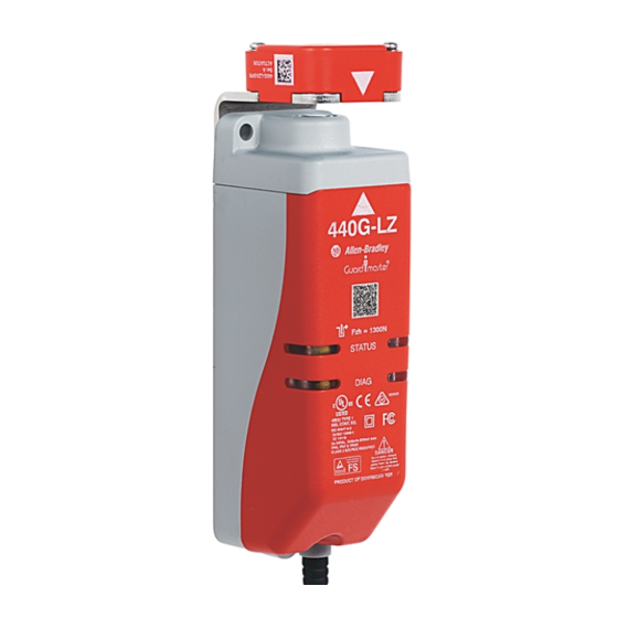
Figure 1 - Assembly Overview
Locking bolt
QR Code
Switch body
Description
Provides general guidelines for installing a
Rockwell Automation guard locking switch.
Provides general guidelines for installing a
1770-4.1
Rockwell Automation industrial system.
http://
Provides declarations of conformity,
certificates, and other certification details.
http://
Actuator
Actuator mounting
bracket
Alignment
guide
Advertisement
Table of Contents

Related Manuals for Allen-Bradley Guardmaster 440G-LZS21SJLJ


Summary of Contents for Allen-Bradley Guardmaster 440G-LZS21SJLJ
-
Page 1: Table Of Contents
You can view or download publications at http:// impaired. www.rockwellautomation.com/literature/. To order paper copies of technical documentation, contact your local Allen-Bradley distributor or Rockwell Automation sales representative. Topic Page Introduction Summary of Changes... -
Page 2: Mounting
440G-LZ Guard Locking Safety Switch Installation Considerations This 440G-LZ Guard Locking switch is for use on guards that are engineered to be rigid without sag. A separately mounted latch (for Figure 4 - Orientation of Assembled Switch example, magnetic, mechanical) and mechanical stop is required. Installation must be in accordance with these instructions and must be carried out by qualified personnel. -
Page 3: Auxiliary/Manual Release
440G-LZ Guard Locking Safety Switch Auxiliary/Manual Release Figure 7 - Actuator Alignment (Three Methods) 1. By setting gap “G” Operation of the auxiliary release causes a fault condition. 2.5 mm (0.09 in.) To reset the switch, cycle the power. [0…5 mm (0…0.19 in.)] Figure 8 - Manual Release Operation [mm (in.)] 2. -
Page 4: Connections
440G-LZ Guard Locking Safety Switch Connections Figure 10 - Eight-pin Micro (M12) or Cable Version Five-pin Micro (M12) 3 Lock Command 2 24V DC+ 8 Safety A+ Keyway 1 Aux 4 Safety B+ 7 0V 5 Safety A 6 Safety B Color Function Color... - Page 5 440G-LZ Guard Locking Safety Switch Specifications IEC 60947-5-3, IEC 60947-5-1, IEC 61508, EN ISO 13849-1, IEC Standards Operating Characteristics (continued) 62061, ISO 14119, UL 508 Safety classification: Guard door sensing Impulse withstand voltage Uimp PLe Category 4 per ISO 13849-1, SIL 3 per IEC 61508 and IEC 62061 1 kV and lock monitoring (IEC 60947-1)
- Page 6 Rockwell Automation maintains current product environmental information on its website at http://www.rockwellautomation.com/rockwellautomation/about-us/sustainability-ethics/product-environmental-compliance.page. Allen-Bradley, ArmorBlock, Rockwell Automation, Rockwell Software, and SensaGuard are trademarks of Rockwell Automation, Inc. Trademarks not belonging to Rockwell Automation are property of their respective companies. Rockwell Otomasyon Ticaret A.Ş., Kar Plaza İş Merkezi E Blok Kat:6 34752 İçerenköy, İstanbul, Tel: +90 (216) 5698400...
Need help?
Do you have a question about the Guardmaster 440G-LZS21SJLJ and is the answer not in the manual?
Questions and answers