Table of Contents
Advertisement
Quick Links
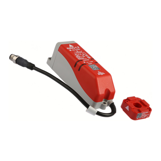
440G-LZ Guard Locking Switch
Installation Instructions
Original instructions in English
ATTENTION: Read this document and the documents
listed in the Additional Resources section about
installation, configuration and operation of this equipment
before you install, configure, operate or maintain this
product. Users are required to familiarize themselves with
installation and wiring instructions in addition to
requirements of all applicable codes, laws, and standards.
Activities including installation, adjustments, putting into
service, use, assembly, disassembly, and maintenance are
required to be carried out by suitably trained personnel in
accordance with applicable code of practice.
If this equipment is used in a manner not specified by the
manufacturer, the protection provided by the equipment
may be impaired.
Additional Resources
The QR Code on the switch provides a link to the 440G-LZ Guard Locking Switch User Manual
(440G-UM001A-EN-P).
Resource
440G-LZ Guard Locking Switch User Manual
Industrial Automation Wiring and Grounding Guidelines,
publication
1770-4.1
Product Certifications website,
http://
www.rockwellautomation.com/products/certification
You can view or download publications at http://www.rockwellautomation.com/literature/. To
order paper copies of technical documentation, contact your local Allen-Bradley distributor or
Rockwell Automation sales representative.
Introduction
ATTENTION: Do not attempt to install this device unless
the installation instructions have been studied and
understood. This document acts as a guide for a typical
installation and is available in some languages at
www.rockwellautomation.com/literature. Select the
publication language and type "440G-LZ" in the search
field. A full user manual is also available.
Locking bolt
QR Code
Switch body
Rockwell Automation 440G-IN011B-EN-P — June 2015
Description
440G-UM001A-EN-P
Provides general guidelines for installing
a Rockwell Automation industrial system.
Provides declarations of conformity,
certificates, and other certification
details.
Actuator
Actuator mounting
bracket
Alignment
guide
This 440G-LZ Guard Locking switch is for use on guards that are engineered so as to be rigid
without sag. A separately mounted latch (e.g. magnetic, mechanical) and mechanical stop is
required.
Installation must be in accordance with these instructions and must be carried out by qualified
personnel.
ATTENTION: After installation, ensure that there is no
possibility of lifting the actuator over the extended locking
bolt. Adherence to the recommended maintenance
instructions forms part of the warranty.
This device is intended to be part of the safety-related control system of a machine. Before
installation, a risk assessment must be performed to determine whether the specifications of
this device are suitable for all foreseeable operational and environmental characteristics of the
application. Refer to the Specifications for certification information and ratings.
Use appropriate screws, bolts, or nuts fitted by tools to mount the switch and actuators to avoid
the risk of tampering. Do not over torque the mounting hardware.
Mounting
Switch body
3 x M5
ATTENTION: For the switch, actuator and actuator
mounting bracket:
• Only use the designated mounting holes.
• Never drill or use to support other structures such as
conduit, cable ways, or other hardware.
Installation Considerations
Orientation of assembled switch
Actuator
For proper installation, a mini-
mum of two fasteners must be
used, at least one of which
must be fitted to the top row of
holes, closest to the bend in
the actuator mounting bracket.
2 x M5/M6 CSK
Advertisement
Table of Contents

Related Manuals for Allen-Bradley 440G-LZ


Summary of Contents for Allen-Bradley 440G-LZ
-
Page 1: Installation Instructions
Installation Instructions Original instructions in English This 440G-LZ Guard Locking switch is for use on guards that are engineered so as to be rigid without sag. A separately mounted latch (e.g. magnetic, mechanical) and mechanical stop is ATTENTION: Read this document and the documents required. - Page 2 2 440G-LZ Guard Locking Switch Actuator setting ATTENTION: After installation, ensure that there Four directions of is no possibility of lifting the approach. actuator over the extended locking bolt. ATTENTION: After installation, ensure that there...
- Page 3 440G-LZ Guard Locking Switch 3 Dimensions [mm (in.)] Connections 9.525 (0.37) dia. 3 Lock Command 2 24V DC+ (0.37) 8 Safety A+ Keyway 1 Aux (1.29) 22.5 4 Safety B+ (0.88) 7 0V 5 Safety A 2 x 5.5 134.5 (5.29)
-
Page 4: Specifications
10 Cable M12 8-pin Allen-Bradley and Rockwell Automation are trademarks of Rockwell Automation, Inc. Trademarks not belonging to Rockwell Automation are property of their respective companies. Publication 440G-IN011B-EN-P — June 2015 Copyright © 2015 Rockwell Automation, Inc. All rights reserved. Printed in the USA.
Need help?
Do you have a question about the 440G-LZ and is the answer not in the manual?
Questions and answers