Table of Contents
Advertisement
Quick Links
Installation Instructions
Original Instructions
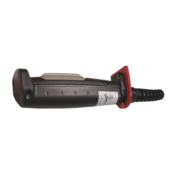
440J-N Enabling Switch
Catalog Numbers 440J-N21TNPM, 440J-N21TNPM-NP, 440J-N2NTNPM-NE
Precautions for Safety
Turn off the power to the grip switch before installation, removal,
wiring, maintenance, and inspection. Use correct size wires to meet
voltage and current requirements. Tighten the terminal screws to the
recommended tightening torque.
Purpose:
This grip switch is a device for enabling a machine (robot, and forth)
when teaching the machine in a hazardous area manually. Configure
the enabling system so that the machine can operate when the switch is
in position two.
ATTENTION: Do not defeat, tamper, remove, or bypass this unit.
Severe injury to personnel could result.
Applicable Wire Size in Terminal
<Direct wiring>: 0.14...1.5 mm
Wire Grip Switch according to IEC60204-1
IMPORTANT
When using a stranded wire, make sure the terminals are not
short-circuited.
40 (1.57)
27 (1.06)
Recommended ferrules (Phoenix™ Contact)
2
2
(0.005...0.06 in.
) X1pc
Also, do not solder the core wires.
Use copper Wire 60/75°C (140/
167°F) only (UL 508).
6 (0.24)
Type
AI0.5-8WH
AI0.75-8GY
AI1.0-8RD
AI1.5-8BK
Mounting Bracket (option)
50
20
(1.97)
(0.79)
33
(1.30)
81
(3.19)
Connector (one connector included with enabling switch)
M20 x 1.5 (0.06)
13 (0.51)
max.
Torque Settings
Applicable Wires
2
0.34...0.5 mm
(0.013...0.019 in.)
2
0.5...0.75 mm
(0.019...0.029 in.)
2
0.75...1.0 mm
(0.029...0.039 in.)
2
1.0...1.5 mm
(0.039...0.059 in.)
3.0 (0.12)
2-∅5.3 (0.21)
86
(3.39)
440J-A00N
4.0 ± 0.3 N•m
4.0 ± 0.3 N•m
1.2 ± 0.1 N•m
0.5 - 0.6 N•m
Advertisement
Table of Contents

Related Manuals for Allen-Bradley 440J-N Series


Summary of Contents for Allen-Bradley 440J-N Series
- Page 1 Installation Instructions Original Instructions 440J-N Enabling Switch Catalog Numbers 440J-N21TNPM, 440J-N21TNPM-NP, 440J-N2NTNPM-NE Precautions for Safety 6 (0.24) Turn off the power to the grip switch before installation, removal, Type Applicable Wires wiring, maintenance, and inspection. Use correct size wires to meet AI0.5-8WH 0.34…0.5 mm (0.013…0.019 in.)
- Page 2 One example of the circuit; safety relay module, MSR127RP Pushbutton switch: 1 N.O. contact (Terminal 7-8) manufactured by Allen-Bradley® Guardmaster®. Note: Use the monitoring device (safety relay module) providing it has the capacity to detect a cross short circuit. Wire the channels 1 and 2 of...
- Page 3 440J-N Enabling Switch Technical Specifications Attribute Value Conforming to standards IEC 60947-5-1, EN 60947-5-1, GS-ET-22, JISC8201-5-1, UL 508 (UL Listed), CSA C22.2 No. 14 (cUL Listed) Certifications CE Marked for all applicable directives, cULus, TÜV SUD Contact configuration 3-position switch Two contacts Auxiliary contacts 1 N.C.
- Page 4 /overview.page You can view or download publications at http://www.rockwellautomation.com/global/literature-library/ overview.page. To order paper copies of technical documentation, contact your local Allen-Bradley distributor or Rockwell Automation sales representative. Rockwell Automation maintains current product environmental information on its website at http://www.rockwellautomation.com/rockwellautomation/about-us/sustainability-ethics/product-environmental-compliance.page.
Need help?
Do you have a question about the 440J-N Series and is the answer not in the manual?
Questions and answers