Table of Contents
Advertisement
Quick Links
Advertisement
Table of Contents

Subscribe to Our Youtube Channel
Related Manuals for Kanardia Nesis III


Summary of Contents for Kanardia Nesis III
- Page 1 Nesis III — Installation Manual Kanardia d.o.o. January 2019 © Kanardia d.o.o.
- Page 3 In short, the license gives you right to copy, reproduce and modify this document if: ˆ you cite Kanardia d.o.o. as the author of the original work, ˆ you distribute the resulting work only under the same or similar license to this one.
- Page 4 Nesis III — Installation Manual Rev. Date Description Jan 2019 Complete manual rework. © Kanardia 2018...
-
Page 5: Table Of Contents
Nesis III — Installation Manual CONTENTS Contents 1 Introduction 1.1 Icons Used Trough the Manual ....1.2 Warnings ...... - Page 6 Nesis III — Installation Manual CONTENTS 7 USB 7.1 USB Memory Stick ......31 7.2 WiFi Module ......31 7.3 USB Cable As Charger .
- Page 7 Nesis III — Installation Manual CONTENTS 11 Service Settings 11.1 Layout ....... . 53 11.2 Parameters .
- Page 8 Nesis III — Installation Manual CONTENTS 16 Autopilot 17 Special 18 CAN Devices 18.1 Indu Layout Change ......76 18.2 Enable/Disable Magnetic Heading .
-
Page 9: Introduction
Nesis III — Installation Manual 1. Introduction Introduction First of all we would like to thank you for purchasing our product. Nesis is a complex instrument and we strongly recommend reading the manuals before installation. You may be also interested in reading: ˆ... -
Page 10: Minimal System
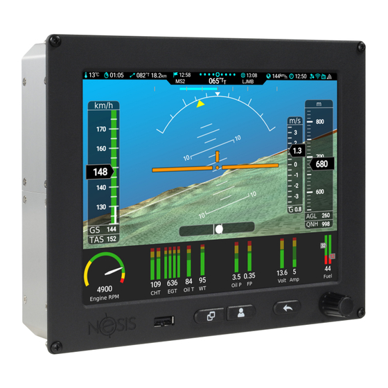
Minimal System Nesis minimal system consists of two components: Nesis III display and DAQU (engine management box). They are sold together as a kit. This manual starts with the installation instructions for the minimal system and then adds separate sections for optional components. -
Page 11: Main Display Dimensions
Cut your instrument panel according to your Nesis display size using cut-out dimensions and cut-out templates. The cut-out drawing can be downloaded from our web page: www.kanardia.eu/support/manuals/, search for the Nesis III Cutout.pdf or for Nesis III Cutout.dxf. Please note that the © Kanardia 2018... - Page 12 Nesis III — Installation Manual 2.3 The Cutout 23.4 41.3 16.9 Figure 1: Nesis side view with dimensions. cutout tolerance was already added to the green cutout line. Figure 4 illus- trates the cutout dimension. Some mounting notes: ˆ The display is mounted from front.
- Page 13 Nesis III — Installation Manual 2.3 The Cutout 210.3 Figure 2: Back view with dimensions. Figure 3: Nesis top view. is necessary, because some printers or PDF rendering software may slightly adjust the document size, producing wrong cut-out dimensions. If possible, make a cutout with a CNC equipment. You can use the dxf file to program the CNC.
-
Page 14: Mounting Procedure
Nesis III — Installation Manual 2.4 Mounting Procedure Green line is coutout line. A tolerance of 0.4 mm was already added. No extra tolerance is needed. Dashed line represents bezel outer contoure. 211,1 Drill 3.5 mm hole to fit M3 screw. -
Page 15: Fixation With Supplied M3 Nut And Lock Washer
Nesis III — Installation Manual 2.4 Mounting Procedure 2.4.1 Fixation with Supplied M3 nut and Lock Washer This is the most straightforward method of fixation. Figure 5 shows an ex- ample. Figure 5: An example of fixation using supplied M3 nut and lock washer. -
Page 16: Fixation With Threaded Rivet Nut Insert
Nesis III — Installation Manual 2.4 Mounting Procedure Once pressed, the nut shall not turn when Nesis is removed and this makes servicing easier. The hole size needs to be as accurate as possible. It is recommended to do a few tests on a scrap part first. -
Page 17: Fixation With Spacer Stud And Epoxy
Nesis III — Installation Manual 2.4 Mounting Procedure Figure 7: Example of rivnuts inserts. Left: a rivnut before compressing. Right: a compressed rivnut. – instrument panel, – rivnut. 2.4.4 Fixation with Spacer Stud and Epoxy As another alternative, a M3 nut can be epoxied to the back of the instrument panel. -
Page 18: Power Installation
Nesis III — Installation Manual 3. Power Installation Figure 8: Example of spacer stud fixed with epoxy: – spacer stud, – panel surface sanded with 60 grid sandpaper, – spacer stud sanded with dremel tool, coat removed, – spacer stud fixed with epoxy mixed with cotton flox. -
Page 19: Circuit Breaker
, which protects against voltage spikes. A coil in relays without this diode may cause spikes that exceed 100 V and they propagate on the system bus. Such spikes may cause permanent damage on Kanardia equipment and other avionics. Backup Battery This backup battery solution works only on 12V systems. - Page 20 Nesis III — Installation Manual 3.3 Backup Battery if there is no voltage on the system bus, backup power is used. UPSU will switch between both sources automatically. UPSU also charges the backup battery when system voltage is high enough (13V or more).
-
Page 21: Gnss Antenna Installation
Nesis III — Installation Manual 4. GNSS Antenna Installation The following table shows approximate elapsed backup times that were ob- tained from 1.2 Ah 12 V battery for some typical configurations. Longer elapsed time can be achieved by using a battery with larger capacity (2 Ah, 2.7 Ah, 3.4 Ah, . - Page 22 Nesis III — Installation Manual 4. GNSS Antenna Installation ˆ The mouning location shall be level, clean and flat. ˆ Try to avoid other transmitting antennas – the location shall be at least 1 m away. ˆ Avoid placing it next to other active GNSS antennas as they may cause interference.
-
Page 23: Gnss Signal Check
Nesis III — Installation Manual 4.1 GNSS Signal Check GNSS Signal Check Nesis can show the GNSS satellite constellation and quality of the reception. This is accessible under the Info icon. 1. Select Options on the main menu. 2. Select the Info icon. -
Page 24: Outside Air Temperature Sensor
Nesis III — Installation Manual 5. Outside Air Temperature Sensor HDOP, VDOP and PDOP values indicates quality of the solution. The meaning of the DOP values is given in Tablet:gnss-dop. In general, HDOP shall be always be less than 5. - Page 25 Nesis III — Installation Manual 5.2 Connection OAT information is required to calculate the true airspeed from the indi- cated airspeed and altitude, as well as to provide the outside air temperature information. In order to provide accurate measurements, the OAT probe must be installed...
-
Page 26: Connection
Nesis III — Installation Manual 5.2 Connection Figure 15: Inserting the OAT probe (left), cap is in place, tighten the internal nut, slide the insulation shrink sleeve (right). 4 … 1 1 … 4 Figure 16: Designation of the pins. -
Page 27: Audio And Video
Nesis III — Installation Manual 6. Audio and Video Audio and Video Nesis can be connected to the audio system (audio out) and video (video in). These two have nothing in common – audio and video are not associated. Audio connection is used to allow Nesis to send out some audio messages, mostly warnings, which can be then heard in the headset. -
Page 28: Funke Atr833
Nesis III — Installation Manual 6.1 Audio Connection Trig TY91/TY92 - 25 pin D-SUB Mono 3.5mm Jack SIGNAL Figure 17: Schematic for connecting Nesis audio to Trig TY91/TY92 radio station. 6.1.2 Funke ATR833 Audio output of the Nesis must be connected to the external audio input on Funke ATR833 radio station. -
Page 29: Dittel Krt2
Nesis III — Installation Manual 6.1 Audio Connection The Funke ATR833 radio station must be configured to accept audio from Nesis. Please follow this steps to configure external audio input on Funke ATR833 radio: ˆ press button SET for at least 5 seconds to enter setup, ˆ... -
Page 30: Video Connection
Nesis III — Installation Manual 6.2 Video Connection ˆ EXT00 - external input always off, ˆ EXT01 - external input always on, ˆ EXT02 - use threshold for enabling external audio - minimum volume, ˆ ˆ EXT09 - use threshold for enabling external audio - maximum volume. -
Page 31: Usb Memory Stick
Nesis III — Installation Manual 7.1 USB Memory Stick Figure 20: An example of video input format selection. USB Memory Stick On order to transfer data between the memory stick and Nesis, the memory stick must meet the following requirements: ˆ... -
Page 32: Usb Cable As Tethering
No actions are required on the Nesis side. Nesis has two CAN bus port. The CAN bus is the main communication bus between Kanardia devices. The CAN bus is a very robust vehicle bus. The communication is message based and connected devices communicate without the host computer. -
Page 33: Connector And Plug
Nesis III — Installation Manual 8.1 Connector and Plug Connector and Plug We are using standard Ethernet computer cable with RJ45 connector on each side. Communication leads are central twisted pair leads – pins 4 and 5, while other pins are used as a power supply for connected devices. -
Page 34: T-Junction
120 Ω Figure 23: CAN line/bus topology principle used by Kanardia Most of the Kanardia devices have two CAN bus ports that allow devices to be daisy-chained to each other. Main bus enter in one port and exits in the other. -
Page 35: Terminator Plug
Nesis III — Installation Manual 9. Service Port main bus Daqu 120 Ω Nesis Airu Nesis master Figure 25: Topology of Nesis basic kit – Daqu also serves as a bus terminator. Because the main bus is very short, second terminator is not really needed. -
Page 36: Port 1 - Auxiliary Rs-232
Nesis III — Installation Manual 9.2 Port 1 – Auxiliary RS-232 Figure 27: Service port D-SUB male with designated pins. Description Autopilot disengage button input. Terminal RX (RS-232) Terminal TX (RS-232) 12 V output, max 200 mA GND – ground... -
Page 37: Autopilot Disengage
Nesis III — Installation Manual 9.3 Autopilot Disengage port. Figure 29 shows the connection schematic. If Nesis and device are both connected to the same power source, the GND connection may be omitted. Aux - RX Device TX Aux - TX... -
Page 38: Rs-232 Ports
Nesis III — Installation Manual 10. RS-232 Ports Optocoupler inside Alarm +12 V Max load 50 mA Figure 31: Alarm switch schematics with the load on the line. Figure 32 illustract solution for a larger load. This load must be connected via relay and the circuit must be protected with a flyback diode. -
Page 39: Pinout
Nesis III — Installation Manual 10.1 Pinout Port 1 – is auxiliary port on the service connector. All these ports are inde- pendent. The names used are merely suggestions. RS-232 PORT 1 RS-232 RS-232 RS-232 PORT 2 PORT 3 PORT 4 Figure 33: RS-232 ports at the back side of the Nesis. - Page 40 Nesis III — Installation Manual 10.2 Configuration Description +12V out – used to power some device. Not used. Not used. RX – receive data. Connect with TX on device. TX – send data. Connect with RX on device. GND – ground.
-
Page 41: Connection Details
Nesis III — Installation Manual 10.3 Connection Details Radio Trig the port is connected with a Trig TY91/TY92 radios. Trig’s slightly modified SL40 protocol adapted for 8.33 kHz channel spacing will be used for communication. Flarm compatible device the port is connected with a Power Flarm, TRX 1500, or some other Flarm compatible device. -
Page 42: Funke Atr 833 Radio
Nesis III — Installation Manual 10.3 Connection Details KRT2 - 15 pin D-SUB TX-PC RJ12 - 6 pin Not used 4 ... RX RX-PC 5 ... TX 6 ... GND Figure 35: Schematic connection for KRT2 and Nesis RS-232 port. -
Page 43: Funke Trt800H Transponder
Nesis III — Installation Manual 10.3 Connection Details ATR833 - 25 pin D-SUB RJ12 - 6 pin Not used DATA RX 4 ... RX 5 ... TX DATA TX 6 ... GND Figure 36: Schematic connection for ATR-833 and Nesis RS-232 port. -
Page 44: Trig Tt21/Tt22 Transponder
Nesis III — Installation Manual 10.3 Connection Details Connect according to Figure 38, brown lead (RXD) from pin 12 on transpon- der with TX lead from RJ12 connector. Connect also GND from RJ12 with one of the grounds on transponder (shield of the cable or blue lead from pin 9). -
Page 45: Power Flarm
Nesis III — Installation Manual 10.3 Connection Details TT21/TT22 - 25 pin D-SUB RJ12 - 6 pin Not used 4 ... GND 5 ... GPS Position in (RX) 5 ... TX 6 ... GND Figure 39: Schematic connection for the Trig TT21/TT22 transponder. - Page 46 Nesis III — Installation Manual 10.3 Connection Details KTX2 - 15 pin D-SUB 2 ... TX RS-232 RJ12 - 6 pin Not used 4 ... RX 13 ... RX RS-232 5 ... TX Figure 40: Schematic connection for the TQ KTX2 transponder.
-
Page 47: Trx 1500
Nesis III — Installation Manual 10.3 Connection Details 10.3.8 TRX 1500 Please read the TRX-1500A User and Installation Manual before any con- nection is made to Nesis. The manual can be obtained from the https: //www.air-avionics.com/ web site. Open the Support menu and then se- lect Old &... - Page 48 Nesis III — Installation Manual 10.3 Connection Details The schematic assumes that Nesis will be connected on port 3 and optional display on port 2. Some displays require 12 V for their operation. In this case Pin 11 shall be also connected with the display connector.
-
Page 49: Air Traffic At1
Nesis III — Installation Manual 10.3 Connection Details Figure 44: TRX 1500 port 2 settings page. Port is connected to display. Figure 45: TRX 1500 port 3 settings page. Port is connected to Nesis. 10.3.9 AIR Traffic AT1 Please read the AIR Traffic Installation Manual before any connection is made to Nesis. - Page 50 Nesis III — Installation Manual 10.3 Connection Details Connection AT1 has a D-SUB26 HD connector on its back side. This is a multi purpose connector and several devices may use it. Schematics shown on Figure 46 shows only connections required to connect data port 3 on AT1 with Nesis.
- Page 51 Nesis III — Installation Manual 10.3 Connection Details Figure 47: Home page of the AT1 device. RS-232 data port 3 was not set yet. Nesis will connect to data port 3. Default protocol for port 3 is Garmin TIS protocol. This must be changed. At the same time we also recommend using higher baud rate.
-
Page 52: Flarm Eagle
Nesis III — Installation Manual 10.3 Connection Details B/Flarm options on Nesis will result in Flarm info is not available message. This does not mean that AT1 device is not working properly. Figure 48: Data port 3 settings required for the communication with Nesis. -
Page 53: Service Settings
Nesis III — Installation Manual 11. Service Settings RJ12 - 6 pin RJ12 - 6 pin 1 ... +12 V 6 ... GND 5 ... RX (Data in) 4 ... TX (Data out) 4 ... RX 5 ... TX 1 ... +12V 6 ... - Page 54 Nesis III — Installation Manual 11.1 Layout Figure 50: Nesis screen layout configuration window example. ˆ AHRS + MAP shows AHRS window on the top and small moving map at the bottom. ˆ AHRS + HSI shows AHRS window on the top and HSI indicator below.
-
Page 55: Parameters
Nesis III — Installation Manual 11.2 Parameters 11.2 Parameters The Parameters window is used to set and tune name, range and color limits for different parameters used by Nesis. Figure 51 shows the options. Figure 51: Various options for parameter settings. -
Page 56: Parameter Editing
Nesis III — Installation Manual 11.2 Parameters Select a layout and Nesis will erase/reset all existing parameters and load parameters from the layout instead. If selected layout does not have any parameters defined, the command is ignored. 11.2.1 Parameter Editing Selection of an item from the Edit section starts parameter editing. -
Page 57: Flap Settings
Nesis III — Installation Manual 11.3 Flap Settings Tiny defines a tiny version of parameter name. It must remain tiny, one or two letter max. It is used where short name does not fit. Color bands define the parameter scale color marking limits. Illustration of the parameter limits is given in the right part of the window. -
Page 58: Trim Sensitivity
Nesis III — Installation Manual 11.4 Trim Sensitivity Time of travel defines approximate time of flap from 0 to 100%. This value is used with combination of flap position sensor to detect the flap move- ment and also to prevent sporadic flap movement messages. -
Page 59: Serial Ports
Nesis III — Installation Manual 11.6 Serial Ports Only these two formats are supported. Please check which format is producing your camera and set it accordingly. 11.6 Serial Ports Nesis has several serial (RS-232) multi purpose ports at the back. Please refer to the section 10 starting on page 38 for details. -
Page 60: Restore
Nesis III — Installation Manual 11.9 Restore 11.9 Restore This command restores backup files from a USB memory stick. The files must be create with a backup process first. The files are expected to be located in Nesis-Backup folder. If only one such folder exists on the USB memory stick, then restore process is automatic. -
Page 61: Yaw Misalignment
Nesis III — Installation Manual 12.1 Yaw Misalignment Figure 55: AHRS Leveling window. 12.1 Yaw Misalignment When the instrument panel is perfectly flat and perpendicular to the airplane x-axis (longitudinal axis) than there is no yaw misalignment and the correction angle is zero. -
Page 62: Roll And Pitch Adjustment
Nesis III — Installation Manual 12.2 Roll and Pitch Adjustment Yaw correction affects the roll and pitch correction as well. Hence it is im- portant to set yaw before roll and pitch adjustments are made. 12.2 Roll and Pitch Adjustment Once yaw correction is known (in most cases it is zero), roll and pitch can be adjusted automatically. -
Page 63: Engine Model
Nesis III — Installation Manual 13.1 Engine Model Figure 57: An example window for engine and sensors. 13.1 Engine Model Engine model shall be selected first. This tells Daqu if this is a classical engine or it has some kind of ECU (Rotax iS, UL-Power, D-Motor, . . . ). For some engines it also tells which software fuel flow calculation models shall be used... -
Page 64: Channels
Nesis III — Installation Manual 13.3 Channels Engine FF-Model Generic engine (any engine) ž Rotax 582 65 HP ž Rotax 912 80 HP ž Rotax 912 100 HP ž Rotax 914 ˆ ˆ Rotax 912 iS ˆ ˆ Rotax 915 iS ž... -
Page 65: Channel Editing
Nesis III — Installation Manual 13.3 Channels Figure 58: An action window example. Channel was already edited hence the offset option is also shown. Reset clears all the channel data and set the channel as not used. Min/Max is used to define the sensor limits, required for some functions like trim and flap. - Page 66 Nesis III — Installation Manual 13.3 Channels Figure 59: An example of channel Z editing. Z is typically used for the engine RPM. Filter defines a low level filtering. This is a low pass filter time constant. A larger value means that more time is needed for a measurement to react on some sensor change.
-
Page 67: Min/Max
Nesis III — Installation Manual 13.3 Channels Figure 60: An example of channel D editing. Certain sensors require addi- tional value, which defines the sensor range. Figure 61: An example of channel A editing. An EGT sensor is connected to the channel. -
Page 68: Offset
Nesis III — Installation Manual 14. Tank Nose holds the value of the pitch trim sensor when trim is at the full forward – nose down position. The value can be entered manually. Tail holds the value of the pitch trim sensor when trim is the full backward position –... -
Page 69: Fuel Level Sensors
Nesis III — Installation Manual 14.1 Fuel Level Sensors 14.1 Fuel Level Sensors After the fuel level sensor channel has been set for certain fuel tank, the tank must be calibrated properly. In principle, this is similar to the Min/Max procedure for trim sensors. -
Page 70: User Shape
Nesis III — Installation Manual 14.1 Fuel Level Sensors Figure 65: An example of linear fuel tank. Typically, the tank is completely drained and a value shown by the fuel level sensor is copied to the Empty. Then, the tank is filled with fuel and the sensor value is copied to the Full. - Page 71 Nesis III — Installation Manual 14.1 Fuel Level Sensors can’t reach the true low fuel point. Select the Add point item and set the Fuel Quantity value to zero (b) First point was added. (a) Starting situation. Figure 66: Editing tank measurement points.
-
Page 72: Predefined Shapes
Nesis III — Installation Manual 14.1 Fuel Level Sensors were needed for a sensor to react. So, the real tank capacity is 46 liters, but Nesis will show values between 0 and 42. Figure 67b shows the final situation. The dark blue color line on the chart shows tank non-linearity. -
Page 73: Simulated Fuel Tank
Nesis III — Installation Manual 14.2 Simulated Fuel Tank 4. Close the window. The tank shape has now been defined and scaled to the min and max sensor position. Predefined shapes also support the Edit option, where individual points can be adjusted. -
Page 74: 15 Offset
Nesis III — Installation Manual 15. Offset Offset Some sensors and counters may require occasional adjustment. The offset window allow adjustment for static and dynamic pressure sensors, CO sensor, fuel flow correction and time counters adjustments. Please make sure that Nesis is running for at least 10 min before any sensor adjustments are made. -
Page 75: Autopilot
Nesis III — Installation Manual 16. Autopilot where fuel flow is computed from engine RPM and manifold pressure for a known engine. Increasing the factor will also increase the calculated fuel consumption. Use software based fuel flow with great care. The indications may be incorrect and this indication will also impact the software based fuel tank, range and endurance, when used. -
Page 76: Can Devices
file with the isb extension. 1. The new LCD layout file for some specific devices is typically obtained from Kanardia customer support as an email attachment. 2. The file is copied to an USB memory stick. -
Page 77: Joyu
Nesis III — Installation Manual 19. Joyu Joyu Joyu has a pretty complex system of push buttons, rotation/push wheel and direction stick. To each of these some special function can be assigned. Furthermore, one Joyu can be used to command several devices connected to the same CAN bus. -
Page 78: Configuration
Nesis III — Installation Manual 19.2 Configuration ˆ Emsis Wheel . . . same as pushing up/down arrow..same as the OK button. Cancel . . . same as pushing the Cancel/Back button. Pager . . . same as pushing the page switching button. - Page 79 Nesis III — Installation Manual 19.2 Configuration Figure 72: Joyu button 1 was assigned to Nesis with serial number 100 with the autopilot menu action. 3. The process is repeated for all buttons. Some of the buttons can remain unused.
- Page 80 Nesis III — Installation Manual 19.2 Configuration Figure 74: Final situation – three different devices are commanded with one Joyu. © Kanardia 2018...
Need help?
Do you have a question about the Nesis III and is the answer not in the manual?
Questions and answers