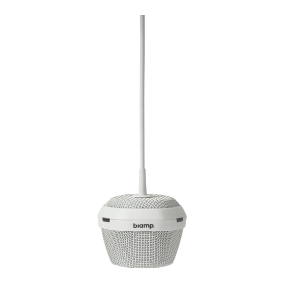
Summary of Contents for Biamp Tesira TCM-1
- Page 1 TCM-1 Beamtracking™ Ceiling Microphone TCM-1A Beamtracking™ Ceiling Microphone with Amplifier TCM-1EX Beamtracking™ Expansion Ceiling Microphone OPERATION MANUAL APRIL 2018...
- Page 2 The TCM-1 microphone actively tracks and intelligently mixes conversations from around the table, allowing far-end conference participants to experience the conversation naturally. The Tesira TCM-1 comes with its own digital signal processing module for beamtracking, and each plenum box comes with an additional RJ-45 connector for daisy-chain connections.
- Page 3 Tesira Help File. For device specifications and microphone polar pattern please consult the datasheet. The Tesira TCM-1, TCM-1A and TCM-1EX do not connect with Telecom Network Voltage (TNV) circuitry and are considered Network Environment Zero devices...
- Page 4 TCM-1 & TCM-1A FRONT PANEL Figure 1 TCM-1A Figure 2 TCM-1 1. AVB/Control Facilitates connection to the Tesira AVB network for audio transmission and control. This RJ-45 port may either be connected directly to the Tesira AVB port (via a PoE+ injector) for a single device system, or via a PoE+ network switch in a multi-device AVB system.
- Page 5 TCM-1 & TCM-1A FRONT PANEL 4. Amp LED (TCM-1A only) A multi-color LED provides information about the status of the amplifier. Status LED Indicator No power Powered Green Solid Amplifier limiter engaged Yellow Solid Amplifier is in Locate mode (triggered from the software) Green Flashing Amplifier has Major Alarm condition Red Flashing...
- Page 6 TCM-1EX FRONT PANEL Figure 3 TCM-1EX 1. Mic (IN) Allows for connection of a single additional TCM-1EX expander microphone unit in a daisy-chain topology, with a maximum of 2 TCM-1EX units per TCM-1 or TCM-1A. Use of this RJ-45 port is optional and will depend on the number of additional microphones required to cover the acoustic space.
- Page 7 Unit is in Locate mode (triggered from the software) Green Flashing Microphone is Muted Red Solid Unit has a Major Alarm condition Red Flashing 2. Biamp Logo Defines the front of the microphone when looking at the Azimuth Angle in the software.
- Page 8 TCM-1, TCM-1A & TCM-1EX WIRING TOPOLOGIES Example Topologies Figure 5 TCM-1A with 2x TCM-1EX Figure 6 TCM-1 with 2x TCM-1EX NOTE: The TCM-1 and TCM-1A cannot be daisy-chained together.
- Page 9 TCM-1, TCM-1A & TCM-1EX WIRING TOPOLOGIES Example Topologies – Amplifier Speaker Wiring Figure 7 Amplifier speaker wiring (TCM-1A only) All speaker wiring connections require Class 2 wiring and should be made by qualified personnel with the amplifier power removed. Channel Assignment & Power Ratings The amplifier can be configured in either single channel or two channel mode in the Tesira software.
- Page 10 TCM-1, TCM-1A & TCM-1EX INTERNAL CONNECTIONS Internal Connections The TCM-1, TCM-1A and TCM-1EX include a folded metal enclosure (plenum) designed for permanent installation on a ceiling or other horizontal surface, above a ceiling tile, or on a vertical surface. The devices are passively cooled and do not have ventilation ports.
- Page 11 TCM-1, TCM-1A & TCM-1EX INSTALLATION Mounting & Installation General Mounting and Installation Notes • The maximum distance between an Ethernet switch and a TCM-1 or TCM-1A plenum box is 330 feet (100 meters). • The maximum distance between daisy-chained TCM plenum boxes is 33 feet (10 meters). •...
- Page 12 TCM-1, TCM-1A & TCM-1EX INSTALLATION Installation Option – Ceiling Mounting NOTE: the plenum cover must be removed for this installation option. No tools are required. 1. Attach the plenum cover to the ceiling with hardware through the keyed mounting holes. 2.
- Page 13 TCM-1, TCM-1A & TCM-1EX INSTALLATION Installation Option – Vertical Mounting NOTE: the plenum cover must be removed for this installation option. No tools are required. 1. Attach the plenum to the vertical surface with hardware through the keyed mounting holes. 2.
- Page 14 TCM-1, TCM-1A & TCM-1EX INSTALLATION Seismic Cable (optional) An optional seismic cable is available for the TCM-1, TCM-1A and the TCM-1EX. 1. To install the seismic cable, locate the holes in the plenum as identified by the arrows. Holes to accommodate the cable are in similar locations for all TCM models.
- Page 15 5. Make sure the ends of the lock mechanism are in the locked position (out) as indicated by the blue arrows. Figure 16 Lock Mechanism Orientation Visit www.biamp.com to obtain firmware and software updates related to this product. To speak with an Applications Engineer, please call 1.503.641.7287 or email...
- Page 16 This equipment is not user serviceable. If trouble is experienced with this equipment, for repair or warranty information, please contact Biamp Systems Corporation, phone number 503.641.7287. If the equipment is causing harm to the telephone network, the telephone company may request that you disconnect the equipment until the problem is resolved.


Need help?
Do you have a question about the Tesira TCM-1 and is the answer not in the manual?
Questions and answers