Table of Contents
Advertisement
INSTALLATION
& OPERATION
MANUAL
3990 SERIES SIRENS
PATENT
PENDING
RLS
I M P O R TA N T:
SIRENS AND CONTROLS
C o n t e n t s :
Introduction .....................................................................2
Standard Features ........................................................2
Unpacking & Pre-Installation......................................4
Installation & Mounting ................................................4
Set-Up and Adjustment ...............................................8
Operation ...................................................................... 1 0
M a i n t e n a n c e ................................................................ 1 5
Troubleshooting .......................................................... 1 6
Wiring Diagram ........................................................... 1 8
Diagnostic Function ................................................... 1 9
O p t i o n s .......................................................................... 1 9
Specifications .............................................................. 1 9
Parts List ....................................................................... 2 1
Warranty ........................................................................ 2 8
Read all instructions and warnings before installing and using.
INSTALLER
This manual must be delivered to the end user
of this equipment.
SERIES
Advertisement
Table of Contents

Subscribe to Our Youtube Channel
Related Manuals for Code 3 RLS 3997


Summary of Contents for Code 3 RLS 3997
-
Page 1: Table Of Contents
INSTALLATION & OPERATION MANUAL 3990 SERIES SIRENS PATENT PENDING SERIES SIRENS AND CONTROLS C o n t e n t s : Introduction ..............2 Standard Features ............2 Unpacking & Pre-Installation........4 Installation & Mounting ..........4 Set-Up and Adjustment ..........8 Operation ..............1 0 M a i n t e n a n c e .............. -
Page 2: Introduction
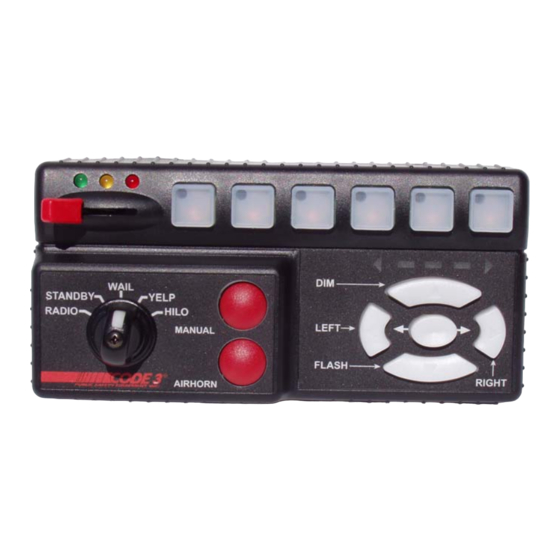
Mastercom siren with microprocessor based circuitry and MOSFET technology. All of the original features are available along with many new added features that are not available on any other Code 3 siren such as; Park Kill, Instant "ON", Adj. Backlighting, " Scroll " Mode and more. - Page 3 3999/3999R Switch A Switch C Switch B - Primary Tones: Wail, Yelp, Hi-Lo, Air Horn 3-Level Switch D - Secondary Tones: HyperYelp, HyperLo Lighting Switch E - 6 auxiliary lighting controls S w i t c h Switch F - Integral Arrow Stik Control - NIGHTPROBE Spotlight controller optionally available...
-
Page 4: Unpacking & Pre-Installation
Status LED - An indicator LED, visible on the front of the remote siren amplifier indicates that the unit is on when lighted. Radio Rebroadcast - Broadcast Two-way radio reception over siren speakers. These inputs are transformer coupled to prevent loading of the radio. Remote Siren Switching - The siren accepts either a positive or a ground (earth) signal, usually from the vehicle's horn switch (or other user supplied switch), to remotely activate the MANUAL or AIR HORN functions. - Page 5 convenience to the operator should be the prime consideration when mounting the siren and controls NOTE: Setups and adjustments will be made in subsequent steps, depending upon the model and options purchased, that may require access to the rear area of the unit. Plan the installation and wiring accordingly. Amplifier Connections Siren Amplifier Connector - As a standard feature, the Siren and Auxiliary sections of your unit...
-
Page 6: Warranty 2
- Connect to the device or circuit that is to be activated by the InterClear feature. The InterClear circuit is internally current limited at 1 Amp. Should your application require higher currents, use the InterClear Power Booster Kit (# INTBS), available from your Code 3 supplier. 1/4" Male Quick-Connect Printed Circuit Board Terminals +12V - Connect to a positive +12 volt DC source. - Page 7 Terminal Plugs - Rear Panel- (See Wiring Diagram page 16) I M P O R T A N T ! Remember auxiliary outputs A,B,D,E,F can supply a maximum of 20 Amps each for a combined total of 30 Amps. Install appropriate fuses in each output wire as close to the siren as possible.
-
Page 8: Setup And Adjustment
NOTE: LEVEL 1, LEVEL 2, LEVEL 3, switch progressively. Switch position 1 provides +12 volts at Level 1 terminal. Switch position 2 provides +12 volts at terminals 1 and 2. Switch position 3 provides +12 volts at terminals 1, 2, and 3. SETUP AND ADJUSTMENT All of the adjustments, except MAXIMUM P.A. -
Page 9: Operation 1
PKILL- If this switch (sw 4) is in the on postition, lighting level-3 will "drop-out" when vehicle is shifted to PARK. This is intended to reduce power consumption while vehicle is not moving. If it is not desired to have level 3 "drop-out" this switch should be set to the " OFF " position on the dip switch. Please note that DIP switch 1 is not used. -
Page 10: Operation
P.A. Volume Knob This control adjusts the level of the P.A. audio produced when keying the microphone and speaking into it. This control also controls the Radio Re-broadcast level when in the " RRB " switch is on. (see SETUP, Radio Rebroadcast Adjustment). O p e r a t i o n IMPORTANT ! The RLS Series Siren has two distinct modes of operation. - Page 11 MANUAL Pushbutton Momentary Switch - Produces the Manual tone as described above. AIR HORN Pushbutton Momentary Switch- Produces the Air Horn tone as described above. SLIDE SWITCH - The slide switch located on the front of the siren amplifier selects the function for the REMOTE (external switch) circuitry.
- Page 12 Switch Operation - 399xR Control Head, Hit-N-Go Mode Selected Function Description RADIO - In the RADIO position, the audio from the 2-way radio is rebroadcast over the siren speaker. Note: the siren tones are disabled in this mode. The Air Horn switch will operate normally. STANDBY - In STANDBY mode no siren tone is produced.
-
Page 13: Option
WAIL - This mode produces the Wail tone. Depressing the MANUAL button will now produce Manual wail tone and ramp up until released. Depressing the AIR HORN button will produce the Air Horn sound. The siren can be scrolled in this position as described above. The Remote/Horn Ring input will also activate the Interclear output for approximately 60 seconds. - Page 14 AUXILIARY SWITCH "E" - Supplies power to the load connected to terminal SW E. AUXILIARY SWITCH "F" - Supplies power to the load connected to terminal SW F. NOTE: The six auxiliary switches described above have their own individual LED which is dimly illuminated for back lighting and bright to indicate that the circuit is On.
-
Page 15: M A I N T E N A N C
M A I N T E N A N C E Your Code 3 3990 series siren has been designed to provide trouble free service. In case of difficulty, see Troubleshooting (page 16,17 ). Also check for shorted or open wires. The primary cause of short circuits has been found to be wires passing through firewalls, roofs, etc. -
Page 16: Troubleshooting
T R O U B L E S H O O T I N G (Refer to wiring diagram page 15) PROBABLE CAUSE P R O B L E M R E M E D Y A. PARK KILL ACTIVATED A. -
Page 17: Specifications 1
T R O U B L E S H O O T I N G (Refer to wiring diagram page 15) PROBABLE CAUSE P R O B L E M R E M E D Y A. REFER TO SETUP A. - Page 18 C O M 1 6 G A SW A S P K R 1 6 G A SW B SW C N.C. BK LTG SW C COM P KILL SW C N.O. R R B SW D R R B SW E I N T E R C L E A R SW F...
-
Page 19: Diagnostic Function
Diagnostic Function RLS Siren Models 3997 & 3999 features a "walk-around" diagnostic test function. The user may invoke this function by holding the "Air Horn" switch while turning on the vehicle's ignition switch. When the "Air Horn" switch is released the siren will begin a timing sequence which will turn on each control output for about two seconds. - Page 20 Lighting Section Warning Light Control:Progressive switching, 3 levels 50 Amps. maximum combined total to #8 wire Audible alarm (optional). Level 1 30A maximum Green LED Indication Level 2 30A maximum Yellow LED Indication Level 3 30A maximum Red LED indication. Auxiliary Control - SPST ( Aux.
- Page 22 Push Button Switch Control Head, Parts List Ref No. Description Part No. Qty. 8 - 32 x 1/4" Machine Screw T 0 1 3 8 5 Knob, Rectangular T 0 1 9 1 7 4 - 40 x 3/8", Pan Hd Phil, Black Oxide T 0 6 9 3 7 Switch Actuator Keypad, 1x6, Silicone Rubber T 1 0 8 7 8...
- Page 24 Rotary Switch Control Head, Parts List Ref No. Description Part No. Qty. Flat Washer, 3/8" x .020" T00667 Nut, 3/8" -32 x 1/2" x .090" T01082 Switch Assembly w/Harness S55229 Knob, Rectangular T01917 Knob, Selector T03537 Insert, Selector Knob T03538 4 - 40 x 3/8", Pan Hd Phil, Black Oxide T06937 Switch Actuator Keypad, 1x6, Silicone Rubber...
- Page 25 Siren Amplifier, Exploded View...
- Page 26 Siren Amplifier, Parts List Ref No. Description Part No. Qty. Flat Washer, 3/8" T 0 0 6 6 7 #8 - 32 Keps Nut T 0 0 6 7 4 8 - 32 x 5/8 Machine Screw T 0 0 7 6 3 #6 - 32 Rd Hd Phil., Machine Screw T 0 1 0 3 0 #6 x 3/8 Hex Hd, Sheet Metal Screw...
- Page 27 N O T E S...
-
Page 28: Warranty
*Code 3, Inc. reserves the right to repair or replace at its discretion. Code 3, Inc. assumes no responsibility or liability for expenses incurred for the removal and /or reinstallation of products requiring service and/or repair.;...
Need help?
Do you have a question about the RLS 3997 and is the answer not in the manual?
Questions and answers