Table of Contents
Advertisement
INSTALLATION
& OPERATION
MANUAL
SERIES
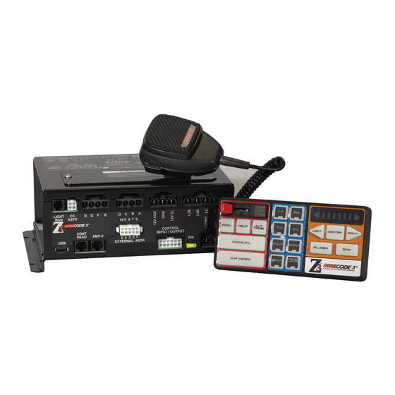
SIREN AND CONTROL HEAD
PATENT PENDING
WARNING
Sirens produce loud sounds that may damage hearing
•
Wear hearing protection when testing
•
Use siren only for emergency response
•
Roll up windows when siren is operating
•
Avoid exposure to the siren sound outside of vehicle
IMPORTANT:
Read all instruction and warnings before installing and using.
INSTALLER:
This manual must be delivered to the end user of this equipment.
Contents:
Introduction ..........................................................................2
Standard Features ...............................................................2
Control Head Configurable (In Vehicle) .....................3
Computer Configurable ..............................................3
Not Configurable .........................................................5
Unpacking & Pre-installation ..............................................7
Installation & Mounting .......................................................7
Amplifier Connections ........................................................8
Amplifier Power Distribution ..............................................9
Control Head Connections .................................................9
Conventional ArrowStik Connections .............................10
Troubleshooting ................................................................12
Siren Wiring Diagram ........................................................14
Siren Specifications ..........................................................15
Lighting Specifications .....................................................16
Siren Control Head, Exploded View .................................17
Siren Control Head, Parts List..........................................18
Siren Amplifier, Exploded View ........................................19
Siren Amplifier, Parts List .................................................20
Siren Cables & Harnesses ................................................21
1
Advertisement
Table of Contents

Related Manuals for Code 3 Z3 Series


Summary of Contents for Code 3 Z3 Series
-
Page 1: Table Of Contents
INSTALLATION & OPERATION MANUAL SERIES SIREN AND CONTROL HEAD Contents: Introduction ................2 Standard Features ...............2 Control Head Configurable (In Vehicle) .....3 Computer Configurable ..........3 PATENT PENDING Not Configurable ............5 Unpacking & Pre-installation ..........7 Installation & Mounting ............7 Amplifier Connections ............8 WARNING Amplifier Power Distribution ..........9 Control Head Connections ..........9... -
Page 2: Introduction
MOSFET technology. All standard features are available along with many new features that are not available on any other Code 3 siren: Fully Configurable 3-Level Switch, Selectable Tones, Adjustable Backlighting and much more. -
Page 3: Control Head Configurable (In Vehicle)
The following features are standard in the Siren (tones and sequences may differ with user selectable configura- tion): Control Head Configurable (In Vehicle) Adjustable Backlighting - Backlighting is independent of siren status. The dimming of the lit push-buttons can be adjusted as desired. - Page 4 Auxiliary A-H Push-Buttons - As configured by the Siren Configuration Software, eight on/off Auxiliary push-buttons are readily accessible for controlling the Auxiliary outputs of the Amplifier. Each Auxiliary push-button can be custom labeled with the supplied label kit. Each push-button is backlighted when activated to alert the operator.
-
Page 5: Not Configurable
and holding the Horn Ring for more than a half second will cause the Siren to generate the Air Horn tone. Load Management - The Load Manager allows setup of three Dropout Voltage Groups by selecting which output to drop out when the vehicle power levels fall below the specified voltage for that group. -
Page 7: Unpacking & Pre-Installation
(see Fig. 2 above). Also reference page 15 and 16 for description of components and Code 3 part numbers. Ease of operation and convenience to the operator should be the prime consideration when mounting the siren and controls. -
Page 8: Amplifier Connections
Amplifier Connections All Amplifier connections are made on one side of the Amplifier as seen in figure 4. See wiring diagram on page 13. All Amplifier connections are quick disconnect requiring no tools. Figure 4 Larger wires and tight connections will provide longer service life for components. For high current wires it is highly recom- mended that terminal blocks or soldered connections be used with shrink tubing to protect the connections. -
Page 9: Amplifier Power Distribution
Connection of a 58 watt speaker to the siren amplifier will cause the speaker to burn out, and will void the speaker WARNING warranty! Amplifier Power Distribution The Level 1, 2, 3A and 3B outputs can supply a maximum of 15 Amps each or a combined total of 50 Amps. Each Level has a 20 Amp fuse installed inside the Amplifier. -
Page 10: Conventional Arrowstik Connections
Siren can connect directly to any Code 3 Centrally Controlled (CC) Lightbar ArrowStik and some non-Code3 CC Lightbar ArrowStiks using Code 3 harness P/N T56629 (see figure 8). This harness is found in the Harness & Cable Bag P/N T56641. Refer to the wiring diagram on page 13. - Page 11 NON-CC WIRING CONNECTIONS Figure 6 Figure 7 CC WIRING CONNECTION Figure 8...
-
Page 12: Troubleshooting
C. DEFECTIVE MICROPHONE C. REPLACE MICROPHONE D. COMMON MICROPHONE CIRCUIT NOT D. CHECK WIRING PROPERLY WIRED. E. CALL CODE 3 FOR LIST OF ADAPTABLE E. INCORRECT MICROPHONE. MICROPHONES. RRB VOLUME LOW, OR NO RRB AT ALL. A. INCREASE RADIO REBROADCAST A. - Page 13 Troubleshooting Continued (Refer to wiring diagram on page 13.) PROBLEM PROBABLE CAUSE REMEDY THE GREEN, AMBER, AND/OR RED LEDS A. ONE OR MORE OF THE 3-LEVEL FUSES A. REPLACE THE FUSE(S) IN THE AMPLI- FLASH RAPIDLY AND CONTINUOUSLY. HAVE BLOWN IN THE AMPLIFIER. FIER.
-
Page 15: Siren Specifications
Siren Specifications Siren Section: Input Voltage 10 to 16 VDC and ground - 12V units (Note: Operation of 12V units above 15 VDC for an extended period of time may result in speaker damage.) Operating Current 100W: 8 Amps @ 13.6V with 11-ohm load (100 Watt Speaker) - 12V units 200W: 14 Amps @ 13.6V with 5.5-ohm load (2-100 Watt Speakers) - 12V units (NOTE: There is no 58 Watt speaker connection available.) Standby Current... -
Page 16: Lighting Specifications
Lighting Specifications Warning Light Control: 3-Level Switch, 4 Outputs, 50 Amps. maximum combined total Level 1 & 2: 15 Amp Maximum Each Level 25 Amp Maximum Total Green (1) & Yellow (2) LED Indication Level 3A & 3B: 15 Amp Maximum Each Level 25 Amp Maximum Total Red (3) LED Indication AUX A thru D:... -
Page 18: Siren Control Head, Parts List
Siren Control Head, Parts List Ref No. Description Purchasable Part No. Internal Part No. (Not For Sale) Qty. 8-32 X 1/4” Hex Head MS T10385 Control Head Mounting Bracket T10924 1/4”-20 X 3/8” Hex Head MS T10912 Circuit Board Support, Nylon T11862 Sheet Metal Base Plate T15287... -
Page 19: Siren Amplifier, Exploded View
Siren Amplifier, Exploded View... -
Page 20: Siren Amplifier, Parts List
Siren Amplifier, Parts List Ref No. Description Purchasable Part No. Internal Part No. (Not For Sale) Qty. Amplifier E Tray T15305 All Amplifier Components Amplifier PCB T11851 Are Purchasable #6-32 X .375” Phil Pan HD MS T04250 #6-32 X 1.875” Hex MF Stdoff T15326 Outputs &... -
Page 21: Siren Cables & Harnesses
Siren Cables & Harnesses Ref No. Description Purchasable Part No. Internal Part No. (Not For Sale) Qty. Light Board Power Harness T56627 Aux A-D Harness T56628 L/R Arrow, Dim, Flash Harness T56629 Level 1, 2, 3A, 3B Harness T56630 Outputs & Dim Ext. Harness T56631 CAT5 Cable Min 20 FT T56649... - Page 22 NOTES...
- Page 23 NOTES...
- Page 24 *Code 3®, Inc. reserves the right to repair or replace at its discretion. Code 3®, Inc. assumes no responsibility or liability for expenses incurred for the removal and /or reinstallation of products requiring service and/or repair; nor for the packaging, handling, and shipping: nor for the handling of products returned to sender after the service has been rendered.
Need help?
Do you have a question about the Z3 Series and is the answer not in the manual?
Questions and answers