Table of Contents
Advertisement
24VDC- MODEL(s)
3754
with US tones
& 3764
with European tones
WARNING
Sirens produce loud sounds that may damage hearing
•
Wear hearing protection when testing
•
Use siren only for emergency response
•
Roll up windows when siren is operating
•
Avoid exposure to the siren sound outside of vehicle
IMPORTANT:
T56095 Rev. A
Read all instruction and warnings before installing and using.
INSTALLER:
This manual must be delivered to the end user of this equipment.
INSTALLATION & OPERATION MANUAL
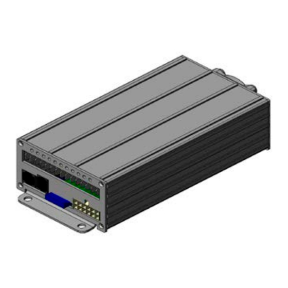
SPRINTER Remote Siren System
with Hand-Held Controller
Contents:
Connections, Fusing & Wire Diagram
Controller functions
Siren Peripherals Diagram
Main PCB Diagram and Fuse Locations 9
Customizing Control Head
European tone locations for Model 3764
Siren &Installation Notes
2
3
3
3
4-6
7
8
10
11
12-16
16
17-18
19
22
Page 1 of 22
Advertisement
Table of Contents

Subscribe to Our Youtube Channel
Related Manuals for Code 3 Sprinter


Summary of Contents for Code 3 Sprinter
-
Page 1: Table Of Contents
INSTALLATION & OPERATION MANUAL SPRINTER Remote Siren System with Hand-Held Controller 24VDC- MODEL(s) 3754 with US tones & 3764 with European tones WARNING Contents: Introduction Standard Features Sirens produce loud sounds that may damage hearing Unpacking & Pre-Installation • Wear hearing protection when testing Installation &... -
Page 2: Introduction
100Watt signal output providing both SAE J1849 and CA Title 13 Compliance. The purpose of this document is to aid in the setup and installation of the SPRINTER, and to provide instructions for its proper operation. -
Page 3: Standard Features
Standard Features The SPRINTER system offers the following features: Primary Tones: Wail, Yelp, Hi-Lo, Manual program selectable Siren tones including Air Horn Vehicle Light Control Buttons PA with Built-In Noise Cancelling Microphone with Integrated Volume Control Radio rebroadcast Park Light function... - Page 4 The SPRINTER amplifier is not waterproof. It must be mounted in a location that is sheltered from rain, snow, standing water, etc. It must also be installed in an adequately ventilated area. Do not install near heater ducts or under the vehicle’s hood.
- Page 5 Figure 1 - Wiring Diagram 3. To install the positive and negative power wires, strip 1/4” of insulation from the end of the wires, and install the blade connectors onto the ends of the appropriate wires. The “+24V” positions may be connected either directly to a +24V source (such as a battery), or through a switch (such as an ignition switch).
- Page 6 4. The unit is supplied with a twelve-position, pluggable connector (white color) for connections to the speaker and other selected optional connections such as hood,grill, radio, horn ring and parklight . Main light bar connections are made at the blade connections in the back of the amplifier unit and are labelled with identification to coincide with the control head.
- Page 7 IMPORTANT WARNINGS TO USERS OF SIRENS: “Wail” and “Yelp” tones are in some cases (such as the state of California) the only recognized siren tones for calling for the right of way. Ancillary tones such as “Air Horn”, “Hi-Lo”, “Hyper Yelp”, and “Hyper Lo” in some cases do not provide as high a sound pressure level.
- Page 8 EXTERNAL 10A SYSTEM FUSE Figure 3 T56095 Rev. A Page 8 of 22...
- Page 9 Figure 4 Figure 5 T56095 Rev. A Page 9 of 22...
- Page 10 Hand Held Controller Label Designations and Functions: Item: Label: Operation: Activation: Description: Bargraph located between the Display CLEAR and EMERGENCY lighted postion along displays a series of keys on the controller lights in 6 positions along bar LIGHTING CONTROLS: Item: Label: Operation: Activation:...
-
Page 11: Public Address System
PUBLIC ADDRESS SYSTEM: Item: Label: Operation: Activation: Description: 14. RADIO Turns on/off radio repeat function (Pressing CLEAR (will switch audio from vehicle will turn off the radio through to the main speaker. radio repeat Adjust volume using the vehicle function.) radio.) 15. - Page 12 CUSTOMIZATION OF THE CONTROL HEAD: (Pass Code must be entered to make certain program adjustments) (Pass Code located on page 21. Remove page before giving manual to end user) Item: Label: Operation: Activation: Description: BACKLIGHTING ADJUSTMENT: 21. PRESS ALT, Adjusts brightness of keys on Up &...
-
Page 13: Programming Capabilities
PROGRAMMING CAPABILITIES: (Pass Code must be entered to make certain program adjustments) (Pass Code located on page 21. Remove page before giving manual to end user) Item: Label: Operation: Activation: Description: FEATURES THAT ARE PROGRAMMABLE: 1. Setting light switch functions 2. - Page 14 PROGRAMMING STEP #1: LIGHT SWITCH FUNCTIONS: Beginning programming mode, the following keys will be illuminated: ,PRIMARY, SEC, LIGHT Indicating Step #1 in Each key will light programming mode. according to its current program state of operation. STATES OF OPERATION: #1 Alternate: LED on #3 Timed: LED fast flashing (0.25 sec.) If not lit, it could be #2 Flashing: LED flashing (0.5 sec.) #4 Momentary:...
- Page 15 For all Euro Tone Programming, refererence Chart 1 on Page 13. A.) Pressing the Secondary (SEC) button once will light up the button. This is enabling that “multiplier”. If the Secondary (SEC) button is pressed again, the button backlighting will turn OFF and disable that “multiplier”.
- Page 16 PROGRAMMING STEP #4: SELECTION OF DIFFERENT 2nd SIREN TONES: the following keys will be illuminated: SIREN 2 (will be illuminated ) Indicating Step #4 in Yellow bargraph will programming mode. light according to its current program tone selected. (Use Up & Down keys to select one of the choices.
- Page 17 For all Euro Tone Programming, refererence Chart 1 on Page 13. A.) Pressing the Secondary (SEC) button once will light up the button. This is enabling that “multiplier”. If the Secondary (SEC) button is pressed again, the button backlighting will turn OFF and disable that “multiplier”.
- Page 18 PROGRAMMING STEP #7: ENABLES PROGRAMMING OF THE EMERGENCY key: the following keys will be illuminated: EMERGENCY (will be illuminated Indicating Step #7 in Pressing any key along with other any programming mode. in EMERGENCY other keys programmed programming mode into the light list.) will include that key function in the list of functions for the...
-
Page 19: Troubleshooting
Press ALT key to exit programming and save or press CLEAR to exit programming without saving. HORN RING TRANSFER FUNCTION: The connection process is the same as standard Sprinter unit. CONNECTING THE GREY WIRE TO GROUND WILL ACTIVATE THE HORN RING FUNCTION. - Page 20 Maintenance: Your Code 3 siren has been designed to provide trouble free service. In case of difficulty, consult the Troubleshooting Guide of this manual. Also check for shorted or open wires. The primary cause of short circuits has been found to be wires passing through fire walls, roofs, etc. If further difficulty persists, contact the factory for troubleshooting advice or return instructions.
- Page 21 Installation Notes: Programming Passcode: Left Arrow Right Arrow Manual Radio REMOVE THIS PAGE AFTER INSTALLATION IF MANUAL WILL BE TRANSFERED TO END USER. T56095 Rev. A Page 21 of 22...
- Page 22 Manufacturer Limited Warranty Policy: Manufacturer warrants that on the date of purchase this product will conform to Manufacturer’s specifications for this product (which are available from the Manufacturer upon request). This Limited Warranty extends for Sixty (60) months from the date of purchase. DAMAGE TO PARTS OR PRODUCTS RESULTING FROM TAMPERING, ACCIDENT, ABUSE, MISUSE, NEGLIGENCE, UNAPPROVED MODIFICA- TIONS, FIRE OR OTHER HAZARD;...
Need help?
Do you have a question about the Sprinter and is the answer not in the manual?
Questions and answers