Subscribe to Our Youtube Channel
Summary of Contents for General DCS200
- Page 1 DCS200-300 MANUAL 071609 FINAL:Manual 7/16/09 1:25 PM Page 1 DCS200/DCS300 USER’S MANUAL & EEKER EEKER VIDEO INSPECTION SYSTEMS Please read this manual carefully and thoroughly before using this product.
-
Page 2: Table Of Contents
DCS200-300 MANUAL 071609 FINAL:Manual 7/16/09 1:25 PM Page 2 CONTENTS Introduction ........ -
Page 3: Introduction
It is widely used in applications such as HVAC/R building, aviation and vehicles maintenance. FEATURES • DCS200: 2.4" (70mm) Color LCD Screen for crystal clear image • DCS300: 3.5" (88.9mm) Color LCD Screen for superb clarity and viewing effect •... -
Page 4: Safety Instructions
DCS200-300 MANUAL 071609 FINAL:Manual 7/16/09 1:25 PM Page 4 SAFETY INSTRUCTIONS Failure to follow the instructions listed below may result in electric shock or personal injury. • Read and understand all instructions prior to any operation. • Do not remove any labels from the product. -
Page 5: Product Components
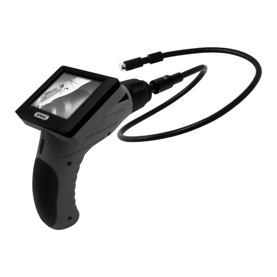
DCS200-300 MANUAL 071609 FINAL:Manual 7/16/09 1:25 PM Page 5 PRODUCT COMPONENTS 1. Hand Held Display Unit 2. Camera Head and Probe 3. Magnetic Tip 4. Hook Tip 5. Mirror Tip A. LCD Screen B. Battery Compartment C. Switch / LED Lighting Adjusting Button D. -
Page 6: Installation
DCS200-300 MANUAL 071609 FINAL:Manual 7/16/09 1:25 PM Page 6 INSTALLATION BATTERY INSTALLATION: 1. Use a screwdriver to open the screw on the battery compartment cover (See Fig. 4). 2. Insert one “9V” alkaline battery (6LR61) into the battery compartment. Close the battery cover and fasten the screw (See Fig. -
Page 7: Connecting The Display Unit To The Camera Head And Probe
DCS200-300 MANUAL 071609 FINAL:Manual 7/16/09 1:25 PM Page 7 CONNECTING THE DISPLAY UNIT TO THE CAMERA HEAD AND PROBE: The display unit must be connected to the cameral head and probe. To connect the probe to the display unit, make sure the keyed ends are properly aligned (See Fig. -
Page 8: Operation Instructions
DCS200-300 MANUAL 071609 FINAL:Manual 7/16/09 1:25 PM Page 8 OPERATION INSTRUCTIONS BASIC OPERATION: To turn the unit on, hold the LCD display unit facing you (See Fig. 9). Roll the switch towards you to turn the power on. The switch then acts as a dimmer for the twin LED’s (See Fig.10), which... - Page 9 DCS200-300 MANUAL 071609 FINAL:Manual 7/16/09 1:25 PM Page 9 the camera head into corrosive, oily places or high temperature objects. 5. Don’t place the cameral head or probe into anything or anywhere that may contain a live electrical charge. Please check following methods to avoid injury.
-
Page 10: Maintenance Instructions
DCS200-300 MANUAL 071609 FINAL:Manual 7/16/09 1:25 PM Page 10 is dropped, check for the breakage which may affect it’s operation. If it is damaged, have the product serviced before using. Many accidents are caused by poorly maintained products. • Use only accessories that are recommended by the manufacturer for your product. -
Page 11: Trouble Shooting
DCS200-300 MANUAL 071609 FINAL:Manual 7/16/09 1:25 PM Page 11 • Upon completion of any service or repair, please ask the service technician to check if the product is in proper working condition. • Stop using the unit if it starts smoking or emitting noxious fumes. -
Page 12: Specifications
DCS200-300 MANUAL 071609 FINAL:Manual 7/16/09 1:25 PM Page 12 SPECIFICATIONS Video Inspection Specifications Recommended use Indoor Viewable Angle 60° Viewable Distance .98" to 11.8" (2.5 to 30cm) Diameter of Camera Head .47" (12mm) DCS200 2.4" TFT/LCD Image Display DCS300 3.5" TFT/LCD... -
Page 13: Cautions
DCS200-300 MANUAL 071609 FINAL:Manual 7/16/09 1:25 PM Page 13 CAUTIONS! • Don’t drop the product or use by force. • Don’t disassemble the product to avoid failure. • Don’t place the product with corrosive gas or objects. • Don’t expose the product in environment which is with shock, too high or too low temperatures. - Page 14 DCS200-300 MANUAL 071609 FINAL:Manual 7/16/09 1:25 PM Page 14 NOTES...
- Page 15 DCS200-300 MANUAL 071609 FINAL:Manual 7/16/09 1:25 PM Page 15 NOTES...
- Page 16 DCS200-300 MANUAL 071609 FINAL:Manual 7/16/09 1:25 PM Page 16 ™ GENERAL TOOLS & INSTRUMENTS 80 White Street New York, NY 10013-3567 PHONE (212) 431-6100 FAX (212) 431-6499 TOLL FREE (800) 697-8665 e-mail: sales@generaltools.com www.generaltools.com DCS200/DCS300 User’s Manual Specifications subject to change without notice ©2009 GENERAL TOOLS &...


Need help?
Do you have a question about the DCS200 and is the answer not in the manual?
Questions and answers