Advertisement
Advertisement
Table of Contents

Related Manuals for Buckleys Dry Roof Pro


Summary of Contents for Buckleys Dry Roof Pro
- Page 1 MANUFACTURERS OF SPECIALIST TEST EQUIPMENT Dry Roof Pro’ Operating Instructions English Version Please read carefully before use...
-
Page 3: Table Of Contents
Dry Roof Pro’’ Contents Page Description Specifications Unpacking Operating instructions Calculating the test voltage Settings Testing Safety precautions Types of fault Maintenance Battery charger Electromagnetic Compatibility Declaration of Conformity Contact Details... -
Page 4: Description
Instruction Manual Description The Dry Roof Pro’ is designed to deliver an adjustable, stabilised DC output voltage for the detection of leaks, defects and porosity in non-conductive flat roof coverings. The Dry Roof Pro’ features a 2x8 character backlit LCD which... -
Page 5: Specifications
Dry Roof Pro’ Specifications Maximum output current: Less than 1mA (continuous) DC sensitivity: Adjustable - 10µA to 450µA (pre-set to 350µA) Batteries: 4 x D-cell Batteries Meter accuracy: Volts: +/-1.0% +/-1 digit Current: +/- 2.0% Current meter FSD: 450µA Test voltage formula:... -
Page 6: Unpacking
Please refer to the specific Buckleys data sheet for details of kit contents. Keep all packaging in case the unit needs to be returned for repair or... -
Page 7: Operating Instructions
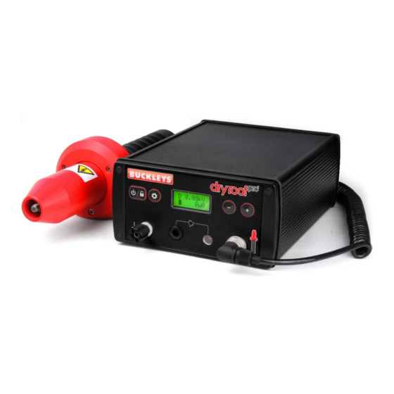
Dry Roof Pro’ Operating instructions ON/OFF/LOCK button Settings button LCD display Earth connection socket Alarm sounder Increase/decrease Test probe & light buttons connection Switch the unit on by pressing the button. The LCD will momentarily show the unit type then the set voltage before displaying the battery condition, the preset voltage and the current conditions. -
Page 8: Calculating The Test Voltage
Instruction Manual Calculating the test voltage Test voltage Test Voltage = 1250 √ T coating coating Where T is coating thickness in Where T is coating thickness in thou/mils (0.001”) microns (0.001mm) Metric calculation example according to NACE RP-02-74 Settings button steps through the user options: Pressing and releasing the select button will sequentially step through the user options. - Page 9 Dry Roof Pro’ Fault detection is indicated by an audible alarm and illumination of a red LED on the front panel. The DC (alarm) sensitivity of the unit should be adjusted to suit the material under test. The value shown in the...
-
Page 10: Safety Precautions
(4mm socket) on the Dry Roof Pro’s test probe handle, or the earthing point on the instrument case. In all cases it is essential to ensure that the instrument is correctly earthed. -
Page 11: Types Of Fault
Dry Roof Pro’ Types of fault Crack Blowhole Air bubble Inclusion Burr Coating Substrate Fig 3. Coating faults Crack: May be encountered with hard coating materials that are applied hot then shrink as they cool or a coating that has been damaged. Cracks can be at an angle and the distance between the electrode and the substrate will be greater, needing a higher voltage to jump the gap. -
Page 12: Maintenance
Instruction Manual Maintenance The Dry Roof Pro’ is designed for minimum maintenance by the user, however the following periodic checks/actions are recommended. Send the entire kit and electrode back to the manufacturer or distributor for recalibration annually. Remove the batteries for transportation, or if the unit is not in use for prolonged periods. -
Page 13: Battery Charger
Dry Roof Pro’ Battery charger Safety • Please read these operating instructions carefully before using the charger. • Do not use the device if there are any signs of damage to the housing, plug or cable. If you do find any damage to the unit, please contact an authorised dealer. - Page 14 Instruction Manual For charging round cells: • Multifunction clear LCD display with backlight • Adjustable charging current for each charging slot 400mA, 600mA, 800mA for 1-4 rechargeable batteries 400mA, 600mA, 800mA, 1500mA, 1800mA for 1-2 rechargeable batteries • Individual charging programs for each charging slot: - CHARGE - DISCHARGE (discharges battery before charging to minimize the ‘memory effect’...
- Page 15 Dry Roof Pro’ Please ensure that the input plug ‘clicks’ into the power supply to ensure the unit is safe to use. Connect the power supply to the charger. Finally, connect the power supply to the mains (100-240V AC 50-60Hz).
- Page 16 Instruction Manual • CURRENT button Push the ‘CURRENT’ button within 8 seconds of selecting a charging program or after inserting batteries to select the charging current for the program ‘CHARGE’ or ‘TEST’. Alternatively, choose the discharging current for the program ‘DISCHARGE’ or ‘REFRESH’. •...
- Page 17 Dry Roof Pro’ If only one or two rechargeable batteries are inserted into the charger using the two outer charging slots, in the mode ‘CHARGE’ and ‘TEST’ the charging current can be increased up to 1500mA or 1800mA with the ‘CURRENT’ button. In this case the inner charging slots are disabled and cannot be used.
- Page 18 Instruction Manual ‘REFRESH’, the display switches between ‘Full’ and the measured discharging capacity in mAh/Ah. ‘ERR’ and ‘Lo’ are displayed alternately if the rechargeable battery inserted has an internal short-circuit and so is defective. ‘ERR’ and ‘Hi’ are displayed alternately if the rechargeable battery inserted exhibits a very high resistance or a non-rechargeable battery is inserted.
-
Page 19: Electromagnetic Compatibility
Dry Roof Pro’ Electromagnetic compatibility Electromagnetic Emissions - European Union Directive 2014/30/EU: Before operating this equipment, it is essential that the following risk assessment be taken. As this equipment will produce an electromagnetic emission when actually arcing down through a fault to earth, a risk assessment of the area in which the unit will be used should be carried out. - Page 20 Again, you should remember neighbouring works. The Dry Roof Pro’ is designed to meet the EMC directive therefore all leads are optimum length. If longer leads are used, then they could transmit similar to aerials and cause interference.
- Page 21 Dry Roof Pro’ Always ensure that the tester and test piece is securely earthed because this will reduce any interference generated by the spark. This also prevents static build-up in the operator and thereby avoiding electric shock. Wherever you are intending to use equipment of this type, on your site or a customers, always obtain clearance from the company safety officer.
-
Page 22: Declaration Of Conformity
Instruction Manual EC Declaration of conformity Buckleys (UVRAL) Ltd As manufacturer of the apparatus listed, declare that the product: Dry Roof Pro’ Is manufactured in conformity with the following directives: 2014/30/EU 2014/35/EU Authorised by: J P Hoveman CEO, Buckleys (UVRAL) Ltd. -
Page 23: Contact Details
Dry Roof Pro’ Contact details Manufacturer: Buckleys (UVRAL) Ltd Address: Buckleys House Unit G, Concept Court Shearway Business Park Shearway Road Folkestone Kent CT19 4RG, UK Tel: +44 (0)1303 278888 Fax: +44 (0)1303 274331 Website: www.buckleysinternational.com Distributor details... - Page 24 Product registration Thank you for choosing a Buckleys product, we are sure it will provide you with many years of reliable service. Please register this product via Buckleys’ website and download the Warranty Registration Certificate. Register your product in 5 minutes...
Need help?
Do you have a question about the Dry Roof Pro and is the answer not in the manual?
Questions and answers