Table of Contents
Advertisement
Advertisement
Table of Contents

Related Manuals for AddSecure IRIS-4 2 Series


Summary of Contents for AddSecure IRIS-4 2 Series
- Page 1 IRIS-4 2 Series Quick Installation and Maintenance Guide...
-
Page 2: Table Of Contents
. . . . . . . . . . . . . . . . . . . . . . . . . . . . . . . . . . . . . . . . . . . . . . . . . . . . . . . . . . . . . . . . . . . . . . . . . . . . . . . . . . . . . . . Touch NG range of AoIP diallers with the same of products from the IRIS-4 2 Series . For the full 2. Product Features . -
Page 3: Package Contents
Maintenance Guide Monitoring Centre (aRC) Make sure that the monitoring centre to which the IRIS-4 2 Series device will send alarm signals is equipped 3. PaCkage ContentS with the appropriate IRIS Secure Apps receiving system . The following information should be obtained from the Monitoring Centre . -
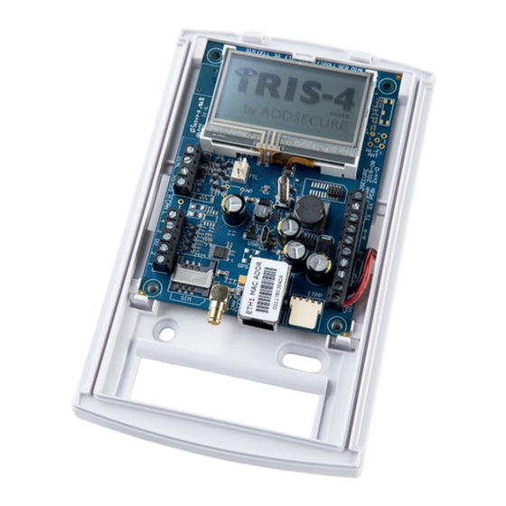
Page 4: Installing The Iris-4 2 Series Dialler
. 6.2. Power ← → The IRIS-4 2 Series dialler can be powered using a Optional serial connection separate or Aux 9-28V DC power supply specified to The following three connections are optional and deliver a minimum 1A current using the screw termi- depend on the panel connection method . -
Page 5: Pin Inputs
It is also possible to link the contacts to the IRIS-4 If at any point a complete default of the dialler is The IRIS-4 2 Series dialler has four pin inputs that To confirm power is applied, look for the indicator... -
Page 6: Panel Configuration
Monitoring Centre . alarm panel. The IRIS-4 2 Series dialler will give a visual indication of the current system status via the ‘SYS LED’ . If Alarm panel integration this is yellow constant light the current setup of the e.g. -
Page 7: Confirm Current Status
Enter the correct reflash password and you will then have the following options . 7.1. Confirm Current Status The IRIS-4 2 Series dialler will indicate “Status – ok” if the current dialler setup is all working correctly, and if the status is showing “Status – Trouble” the Please refer to the IRIS-4 2 Series Engineering dialler has a trouble reported . -
Page 8: Specifications
IRIS-4 2 Series transmission paths Quick Installation and Fault reporting to the alarm panel . If the dialler is unable to poll to the monitoring centre it reports this Maintenance Guide to the alarm panel using a method dependent on the panel interface mechanism: Dial capture: The line voltage is dropped to simulate loss of a PSTN connection . - Page 9 (42 . 4 V peak or 60V dc maximum) The interfaces on the IRIS-4 2 Series have the following safety classifications: •...
Need help?
Do you have a question about the IRIS-4 2 Series and is the answer not in the manual?
Questions and answers