Table of Contents
Advertisement
Quick Links
Installation Instructions
Model ZIC-8B
Zone Indicating Card
INTRODUCTION
Features
P/N 315-048670-11
The Model ZIC-8B from Siemens Industry, Inc., is a zone
indicating card that provides notification appliance circuits for
the FireFinder-XLS/Desigo Fire Safety Modular/Cerberus PRO
Modular system. It has 8 outputs that can be configured as
Class B only for control of audible and visual notification
appliances such as horns, speakers, bells, strobes, etc.
Each zone can be configured independently for different
usages as programmed in the Zeus tool and can be controlled
automatically by program logic or manually using the PMI/
PMI-2/PMI-3 (XLS), FCM2041-U2 (Desigo Fire Safety Modu-
lar), FCM2041-U3 (Cerberus PRO Modular). Installation of a
ZIC-2C Zone Indicating Card on the ZIC-8B gives it two
channel audio capability.
The ZIC-8B supports synchronized and non-synchronized
strobes. This selection is available in the Zeus tool under the
detail properties for each ZIC-8B circuit. Synchronization across
multiple ZIC-8B cards is automatic as a part of the FireFinder-
XLS/Desigo Fire Safety Modular/Cerberus PRO Modular
operating characteristics. Refer to document P/N 315-096363
for a list of strobes that support synchronization.
ZIC-8B features are as follows:
•
Class B circuit configuration
•
Zones can be configured independently
(See Note on Restrictions, page 2)
•
Can have independent input source for
every 2 outputs
•
Zone input voltage supervision per input (DC only)
•
Zone output supervision
•
Intelligent self-restoring power limiting
•
Coded signal synchronization capability
•
Card level Ground Fault detection
•
Communicate H-Net protocol
•
Uploadable firmware update
•
Ability to pass through up to 2A per output circuit
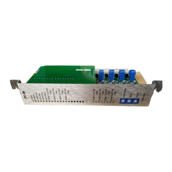
Figure 1
ZIC-8B Zone Indicating Card
Siemens
Siemens Industry
Siemens
Industry
Industry, , , , , Inc.
Siemens
Siemens
Industry
Building
Building
Building
Building T T T T T ec
Building
ec
ec
echnologies Di
ec
hnologies Division
hnologies Di
hnologies Di
hnologies Di
ZIC-8B
RESET
POWER
CARD FAIL
CAN FAIL
HNET FAIL
GND FAULT
ZONE 1 ACTIVE
TRBL
ZONE 2 ACTIVE
TRBL
ZONE 3 ACTIVE
TRBL
ZONE 4 ACTIVE
TRBL
ZONE 5 ACTIVE
TRBL
ZONE 6 ACTIVE
TRBL
ZONE 7 ACTIVE
TRBL
ZONE 8 ACTIVE
TRBL
HUNDREDS
TENS
ONES
HNET/CAN
Industry
Inc.
Inc.
Inc.
Inc.
vision
vision
vision
vision
Advertisement
Table of Contents

Related Manuals for Siemens ZIC-8B


Summary of Contents for Siemens ZIC-8B
-
Page 1: Installation Instructions
This selection is available in the Zeus tool under the ZONE 6 ACTIVE TRBL detail properties for each ZIC-8B circuit. Synchronization across ZONE 7 ACTIVE multiple ZIC-8B cards is automatic as a part of the FireFinder- TRBL ZONE 8 ACTIVE XLS/Desigo Fire Safety Modular/Cerberus PRO Modular TRBL operating characteristics. -
Page 2: Operation
Zone inputs 3-4 feed output circuits 5-8. OPERATION The ZIC-8B contains eight Class B circuits. Each circuit is rated at 2A at 24VDC and has an input connected to the power source and an output where the NAC devices are connected. The zone inputs are isolated from one another and are supervised for the presence of power. - Page 3 GND FAULT (Yellow) Normally OFF . When illuminated, indi- cates that the ZIC-8B has detected either a negative or positive ground fault on its field wiring. ZONE 1 ACTIVE (Red) Normally OFF . When illuminated, indi- cates that Zone 1 is active.
- Page 4 Three rotary dial switches at the bottom of the front panel are used to set the HNET network address of the ZIC-8B. Output Zones The ZIC-8B output zones can be configured as 25V or 70V speaker zones or for the following standard NAC Zone usages: Steady...
-
Page 5: Pre-Installation
(refer to Figure 2): S2, Reset Switch: Momentarily Closed switch that when pressed will initiate a hard ZIC-2C reset to the ZIC-8B (similar to a cold boot). RESET SWITCH S3, S4, S5 Network Address Switch: Set the three-digit HNET network address for... - Page 6 If the ZIC-2C will be used for two channel capability, install it now on the ZIC-8B PC board. Connect the ZIC-2C PC Board to the ZIC-8B by lining up the connector on the ZIC-2C to the receptacle on the ZIC-8B. Gently insert the connector into the receptacle being careful not to bend the connector.
-
Page 7: Installation
The ZIC-8B plugs perpendicularly into one slot in the CC-5/CC-2 card-cage via two 96- pin DIN connectors and can occupy any slot in the card cage. (Refer to Figure 4.) Insert the ZIC-8B card into the card guides right side up (lettering on the front panel is legible) Slide the card in until the card edge connectors contact the receptacles on the motherboard. - Page 8 To calculate the maximum current, the following equation should be used: ZIC-8B Total Current = ZIC-8B Standby Current + [Zone 1 Usage Req. (See Table above) + [Zone 2 Usage Req. (See Table above) + [Zone 3 Usage Req. (See Table above) + [Zone 4 Usage Req.
- Page 9 CONFIGURATIONS The ZIC-8B zones can be configured for Notification Applicance (NFPA 72) as shown below. NOTES Current Max Line 1. All wiring must be in accordance with Draw Resistance Article 760 of NEC or local building codes. Wiring for each zone must be 2.0A...
- Page 10 (CLASS B) ZONE 6 24K, 24K, ONE SLOT OF CC-5 AUDIO FROM PREVIOUS TO NEXT ZIC-8B ZIC-8B OR ZIC-4A OR FROM ZAC-40/ ZAM-180 TERMINALS 1A AND 1B OR 2A AND 2B Figure 6 ZIC-8B Single-Channel Audio Wiring Siemens Industry, Inc.
- Page 11 (CLASS B) (CLASS B) ZONE 6 24K, 24K, ONE SLOT OF CC-5 AUDIO FROM PREVIOUS CHANNEL A ZIC-8B OR ZIC-4A OR TO NEXT FROM ZAC-40/ZAM-180 ZIC-8B CHANNEL B TERMINALS 1A AND 1B OR 2A AND 2B Figure 7 ZIC-8B Two-Channel Audio Wiring (Requires ZIC-2C Board) Siemens Industry, Inc.
- Page 12 Cyber security disclaimer Siemens products and solutions provide security functions to ensure the secure operation of building comfort, fire safety, security management and physical security systems. The security functions on these products and solutions are important components of a comprehensive security concept.
Need help?
Do you have a question about the ZIC-8B and is the answer not in the manual?
Questions and answers